Investigating Modes
Adams Flex lets you set options to help you see the deformation of the flexible body during an animation. In the next sections, you’ll change the contour color, specify a node relative to which the flexible body appears to deform, and scale the deformed mode display. There are many other options available for enhancing the visual representation of the flexible body.
Displaying the Flexible Body Modify Dialog Box
All the changes you make to a flexible body, you make through the Flexible Body Modify dialog box. You display the dialog box just as you would any modify dialog box in Adams View.
To display the Flexible Body Modify dialog box:
1. In the Simulation Control dialog box, select the Reset tool  to return to modeling mode.
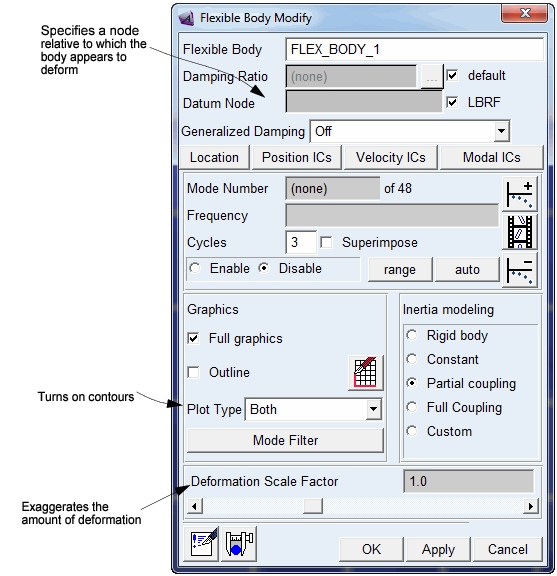
to return to modeling mode. 2. Double-click the flexible body to display the Flexible Body Modify dialog box shown in the next figure.
The figure indicates the three controls that you use to change the deformation display of a flexible body.
Adding Color Contours
In this section, you’ll set Adams Flex so that it changes the color of the flexible link as the link deforms to indicate the magnitude of the deformation.
By default, Adams Flex considers the deformation to be relative to the origin of the flexible body (its local body reference frame (LBRF) or coordinate system). You’ll notice that at the start of the animation, the flexible link is completely blue. As the animation runs, it changes to red to indicate where and when the maximum deformation occurred.
To change the color contour:
1. From the Flexible Body Modify dialog box, set Plot Type to Contour.
2. Click the Results tab on the Adams View ribbon.
3. From the Review container, click the Animation tool  .
.
. Notes: | If you receive the warning shown below you incorrectly selected the Animate tool on the Flexible Body Modify dialog box: Please specify a valid mode number. Be sure to select the Animation tool in the Main toolbox. |
4. In the Animation Controls dialog box, be sure that Contour Plots is selected.
5. Select the Play tool  .
.
. There is a short hesitation before the animation starts because Adams View computes and scales colors based on the deformation that occurred during the simulation.
Setting the Datum Node
Now you’ll set the datum node that you want deformation color changes to appear to be relative to. As explained in the previous section, Adams Flex considers the deformation to be relative to the origin of the flexible body (its LBRF or coordinate system) by default. In this section, you’ll change it to node 1000, which lets you see deformations relative to the nodes at the end of the link that is fixed to ground.
To change the datum node:
1. In the Animation container on the Main toolbox, select the Rewind tool  to reset the animation back to its first frame.
to reset the animation back to its first frame. 2. In the Flexible Body Modify dialog box, clear the selection of LBRF.
3. In the Datum Node text box, enter 1000.
4. Select Apply or press Enter.
5. In the Animation container on the Main toolbox, select the Play tool and observe the color scheme, which is more realistic. You’ll notice that there is a slightly longer hesitation before the animation begins because now there is the added cost of scaling deformation color relative to a datum node.
and observe the color scheme, which is more realistic. You’ll notice that there is a slightly longer hesitation before the animation begins because now there is the added cost of scaling deformation color relative to a datum node. 6. Select the Stop tool  .
.
.Changing the Deformation Scale
In this section, you’ll exaggerate the amount the flexible body deforms so you can see deformations that might otherwise be too subtle to observe. The default scale factor is 1.
1. At the bottom of the Flexible Body Modify dialog box, move the Deformation Scale Factor slider to a value between 2 and 5.
2. In the Animation container on the Main toolbox, select the Play tool to restart the animation.
to restart the animation. Adams Flex now exaggerates the deformations of the flexible body by the amount you requested. The flexible body also appears to be detached from the sphere and from its connection with ground. This is because the motion of a point in a flexible body is the sum of the deformation that is scaled and a rigid body motion that is not scaled.
3. In the Deformation Scale Factor text box, enter 1.0 to set the deformation scale back to 1.0.
4. Select Apply.