Adams View Runtime Body Type Switch
Overview
In Adams through the implementation of new Adams Solver commands, a flexible body's representation can be switched between rigid and flexible during and analysis. This is useful when only a subset of an event requires flexibility in a given component. Simulation time can be reduced by treating some components flexibly for only those portions of the analysis where the result accuracy actually requires it.
In this example you will run a landing gear deployment and drop test. The inner and outer cylinders of the strut are modeled as flexible bodies. You will compare results and run times of cases where these flexible bodies are treated flexibly throughout the analysis, rigidly throughout the analysis and set to switch from rigid to flexible after the deployment portion of the event but just before the landing contact begins.
What You’ll Create
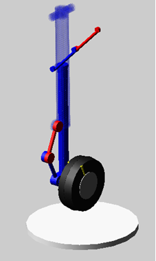
A landing gear model is comprised of a "deadmass" part (1600lbs, no geometry) supported by a landing gear comprised of a deployment/retraction linkage system at the top, upper (outer cylinder) and lower (inner cylinder) struts modeled as flexible bodies, a "torque scissors" (the arms near the wheel), a wheel and the contact pad (ground).
The force "sf_oleo_stops" represents the vertical spring damper and bump-stops acting between the struts. The force "gf_tire" is a simple IMPACT function based force to represent the tire-to-ground contact.
The model is accelerated via gravity up to 72 inch/sec and then, via SFORCE sf_lift, held at this velocity until the wheel first contacts the ground. After this point "sf_lift" disengages and the system is allowed to freely react to the impact.
Runtime Rigid-Flex Switch in Adams View
1. The files required for this tutorial can be found in the Adams installation at: \install_dir\flex\examples\runtime_switch_aview\rigid_flex\. Copy them to your working directory.
2. Start Adams View.
3. Select Existing Model from the startup screen.
The Open an Existing Model dialog box will appear.
4. Select the landing_gear_example.cmd which you copied to your working directory in the first step of this tutorial.
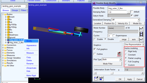
5. The two strut cylinders as modeled flexibly as you could verify via right-click modify and seeing that they employ the default "Partial Coupling" inertia modeling option:
6. Run the baseline analysis (both strut cylinders flexible throughout the run):
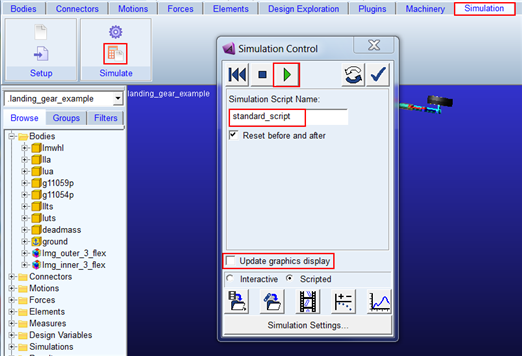
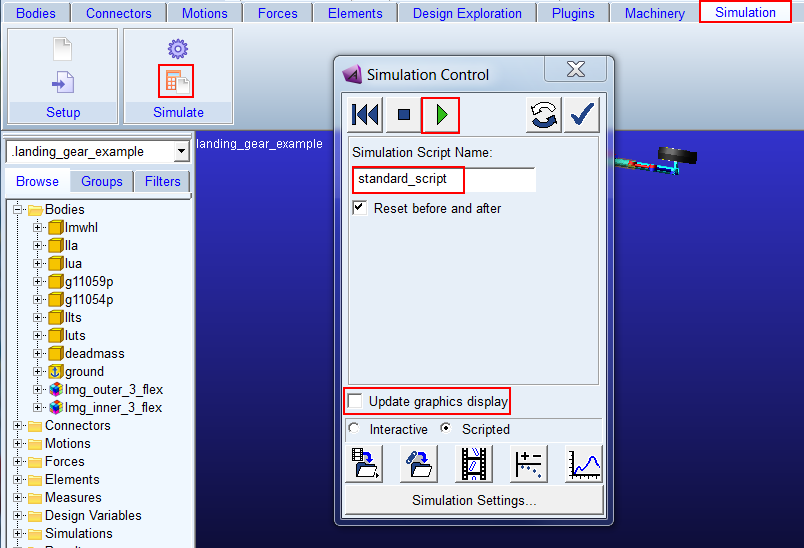
a. Click the Simulation tab on the Adams View ribbon.
b. From the Simulate container, click the Run a Scripted Simulation icon.
c. Browse for the simulation script "standard_script"
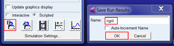
d. Uncheck "Update graphics display"
e. Click Start Simulation icon to start the analyses.
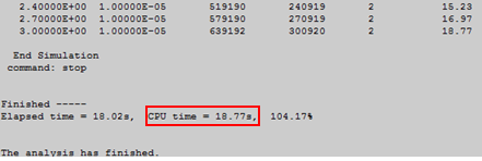
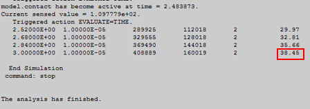
7. The analysis will be run using the external Adams Solver executable and will display progress in the Information window. Once the run completes, note the CPU time used, usually your value may differ due to hardware differences:
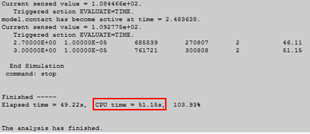
Note: | A sensor is used to detect contact and shut off the lift force as described in the model description at the beginning of this example; so, you will see notifications in the Information window each time the tire contacts the ground. |
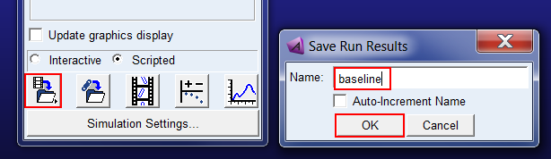
8. Save this analysis as "baseline"
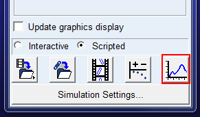
9. Open the Adams PostProcessor window
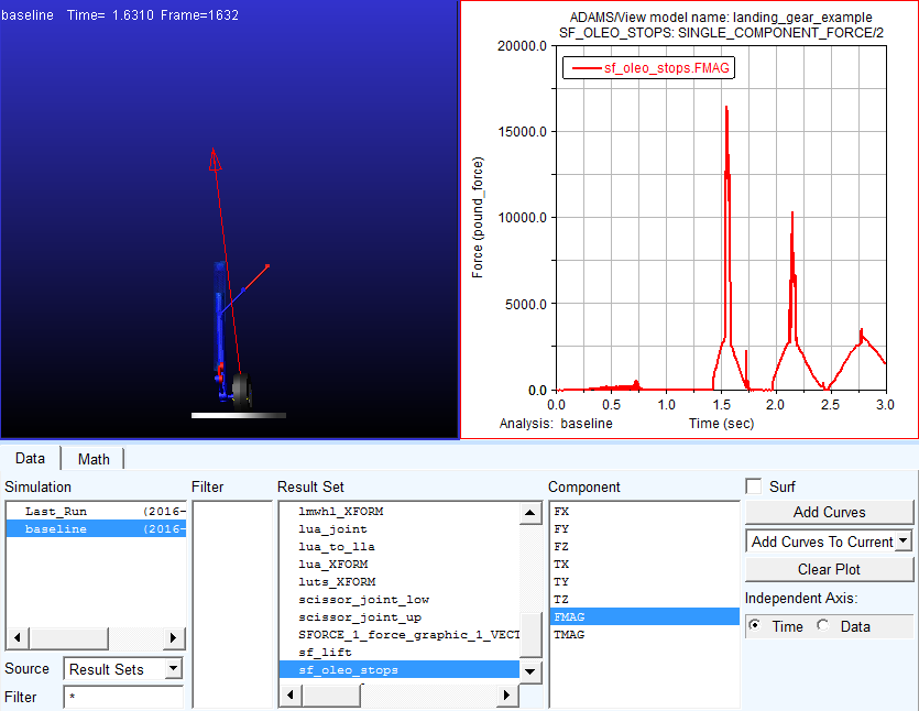
10. Animate the analysis, "baseline" and plot the vertical force in the force representing the strut's spring-damper and bumpstops:
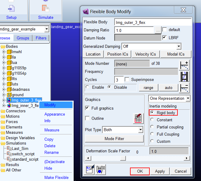
11. Return to the Adams View window and modify the outer strut to behave as a rigid body:
a. From the model browser right click the outer strut flexbody ("lmg_outer_3_flex") and select Modify
b. Select the "Rigid Body" Inertia Modeling option
c. Click OK
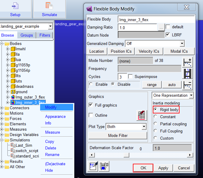
12. Next, do the same for the inner strut:
a. From the model browser right click the inner strut flexbody ("lmg_inner_3_flex") and select Modify
b. Select the "Rigid Body" Inertia Modeling option
c. Click OK
13. Re-run the same simulation script
a. Click the Simulation tab on the Adams View ribbon.
b. From the Simulate container, click the Run a Scripted Simulation icon.
c. Browse for the simulation script "standard_script"
d. Uncheck "Update graphics display"
e. Click Start Simulation icon to start the analyses.
14. Note the CPU time; this run should take significantly less time since you are treating both flex bodies rigidly:
15. Save this analysis as "rigid"
16. Return to the post-processor and compare the force representing the strut's spring-damper and bumpstops between this rigid run and the baseline flexible run from earlier:
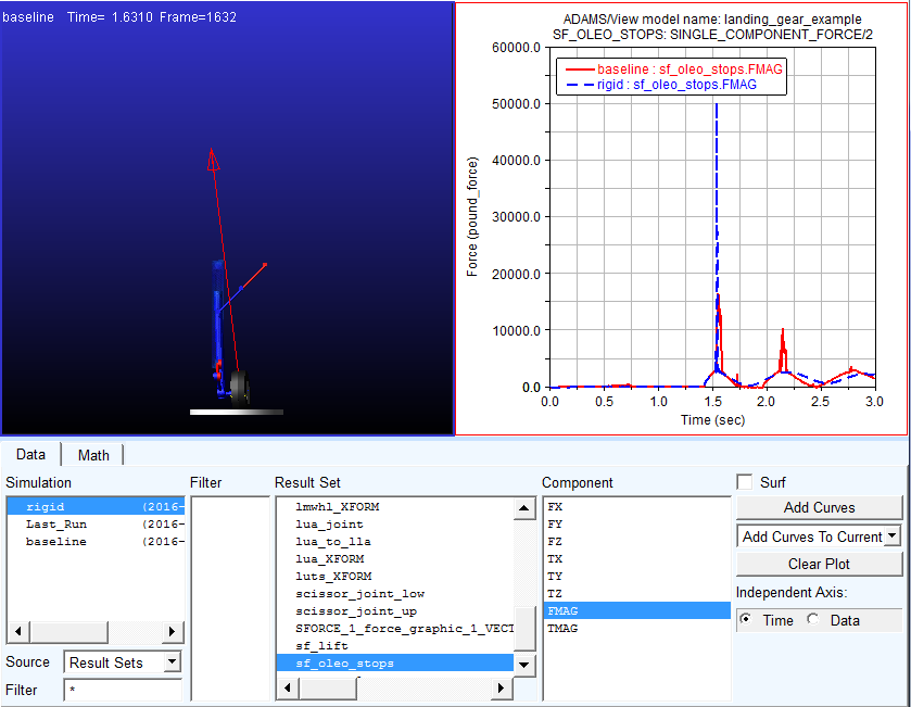
Unsurprisingly the rigid run's first peak is much higher due to the lack of realistic compliance in the strut. You'll notice that the second peak is actually lower compared to the flexible baseline result. This is because the flexible body model rebounds higher after the initial impact and comes down harder on the second bounce.
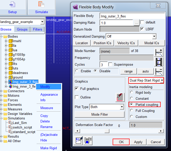
17. Return to Adams View and modify the outer strut to be a "dual representation" body that starts rigid and can be converted to a flexible representation during runtime:
a. From the model browser right click the outer strut flexbody ("lmg_outer_3_flex") and select Modify
b. Revert to "Partial Coupling" for the Inertia Modeling option
c. Select "Dual Rep Start Rigid" from the menu above
d. Click OK
18. Next, do the same for the inner strut:
a. From the model browser right click the inner strut flexbody ("lmg_inner_3_flex") and select Modify
b. Revert to "Partial Coupling" for the Inertia Modeling option
c. Select "Dual Rep Start Rigid" from the menu above
d. Click OK
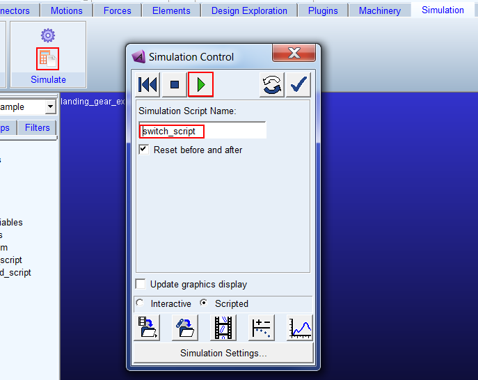
19. A simulation script is in the model which switches the representation of both flexible bodies to flexible at time=1.4 seconds, just before the tire first impacts the ground patch. This should be the most efficient way to run the model since the strut flexibility is not required for the landing gear deployment action but clearly is important for the ground impact. To examine this script: from the model browser right-click the "switch_script" and click Modify.
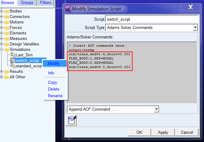
20. The Adams Solver command FLEX_BODY has a new argument: REPRESENTATION=MODAL and REPRESENTATION=RIGID ("REP" for short). This is used to change the representation of a flexible body during runtime. In this example the flexible bodies have the id numbers 1 and 2 (you would list info on them to find this out) so you have the syntax highlighted above. Click "Cancel" in the "Modify Simulation Script" dialog box since you do not want to make any changes.
21. Now, run the model with the "switch_script"
22. You will likely see a run time somewhere between the baseline flexible run and the rigid run.
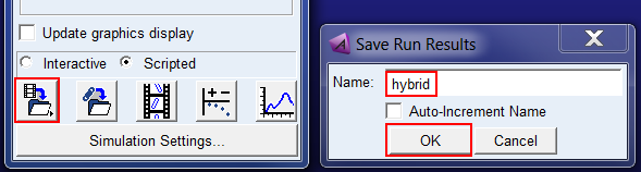
23. Save this analysis as "hybrid"
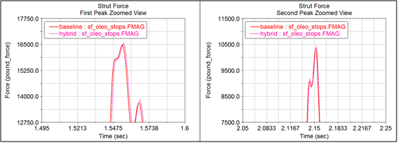
24. Return to Adams PostProcessor and compare the hybrid analysis result for the strut force with the previous runs (always flexible, always rigid). You will see that at the critical point, the impact with the ground, the curves are very similar to each other:
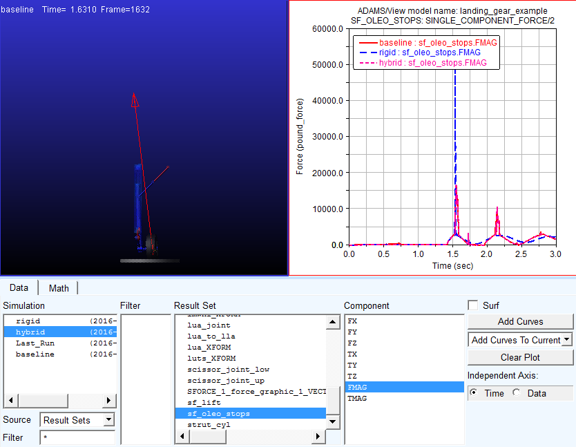
25. Zooming on the peaks, some differences are noticeable. The result comparison will not be line-on-line since the two runs have essentially different initial conditions. Remember, the hybrid run treated the strut parts as rigid bodies until just before the ground contact.