Adams Car Runtime Body Type Switch
Overview
In Adams through the implementation of new Adams Solver commands, a flexible body's representation can be switched between rigid and flexible during and analysis. This is useful when only a subset of an event requires flexibility in a given component. Simulation time can be reduced by treating some components flexibly for only those portions of the analysis where the result accuracy actually requires it.
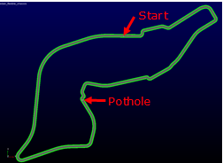
In this example we will run a full-vehicle model around a circuit where at one point a pothole will be encountered. The model will be run three times, once each with body of the car represented rigidly, flexibly and switched from rigid to flexible during runtime just before the pothole.
What You’ll Create
This is a full-vehicle sedan model with a flexible body for the car body. The road is this is a smooth road representation of the Imola race circuit with the addition of 0.07m deep, 10m long pothole at one point. The event drives conservatively along track in two mini-maneuvers: one with an output sampling rate of 0.1 up to just before the vehicle encounters the pothole at 115.1 sec, and a second that samples at 0.001 seconds per step thereafter for another 2.0 sec to get finer output resolution through the high loading and short duration of running over the pothole.
Runtime Rigid-Flex Switch in Adams Car
1. The files required for this tutorial can be found in the Adams installation at: \install_dir\flex\examples\runtime_switch_acar\rigid_flex\. Copy them to your working directory.
2. Start Adams Car Standard Interface.
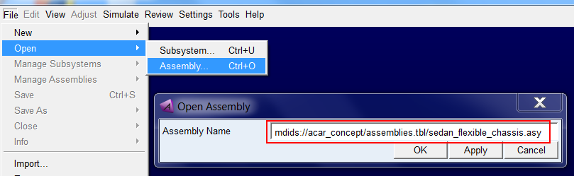
3. Select File → Open → Assembly
4. From the acar_concept database, open the assembly sedan_flexible_chassis.asy.
5. Click OK button to close the dialog box and load the assembly.
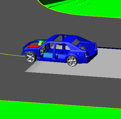
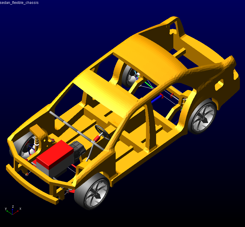
6. The full-vehicle assembly with a flexible body representation of the car body shown below:
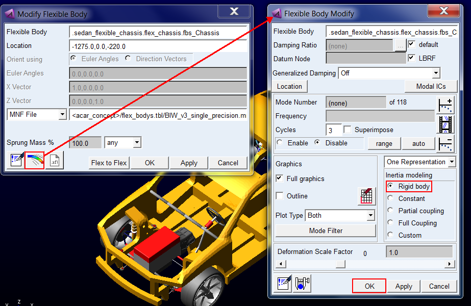
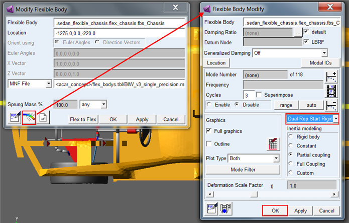
7. To modify the flexible body to use a rigid representation
a. Right-click → Modify
b. From the flexible beam icon open the detailed Flexible Body Modify dialog box
c. Set Inertia Modeling to "Rigid Body" and click OK.
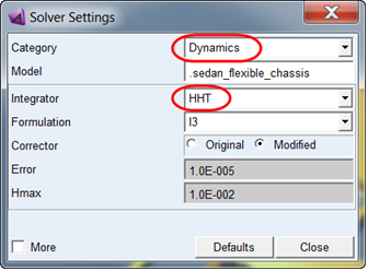
8. Before running analyses select the Adams Solver HHT integrator via Settings → Solver → Dynamics:
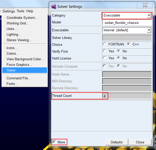
9. Optional: Before running analyses set the number of threads for Adams Solver to 4 via Settings → Solver → Executable → More:
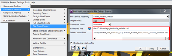
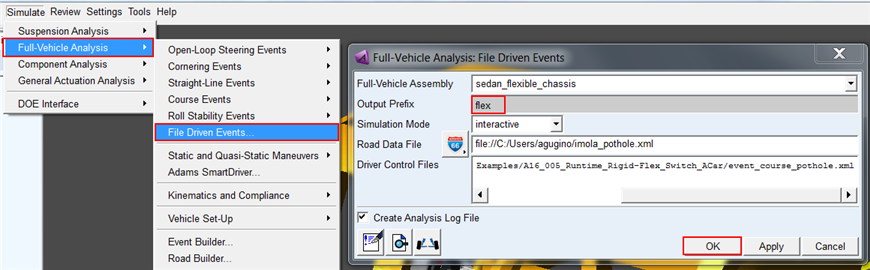
10. Set up the analysis via Simulate → Full-Vehicle Analysis → File Driven Events
a. Output Prefix: "rigid"
b. Road Data File: copy the file included with this example "imola_pothole.xml", place it in your working directory, and browse for it here (this is a smooth road representation of the Imola race circuit with the addition of 0.07m deep, 10m long pothole at one point)
c. Driver Control Files: Select the "event_course_pothole.xml" which you copied to your local directory in the first step of this tutorial. It uses Adams SmartDriver to drive conservatively along track in two mini-maneuvers: one with an output sampling rate of 0.1 up to just before the vehicle encounters the pothole at 115.1 sec, and a second that samples at 0.001 seconds per step thereafter for another 2.0 sec to get finer output resolution through the high loading and short duration of running over the pothole.
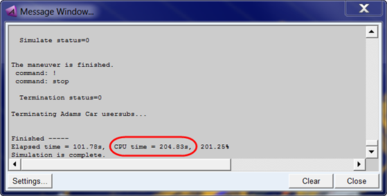
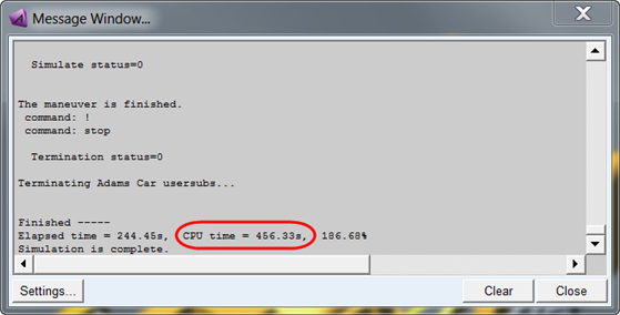
11. Click OK to launch the analysis. It will take a few minutes to run depending on your environment. When it completes note the CPU time consumed.
Note: | Your time will most likely differ from what's shown below due to environment differences. |
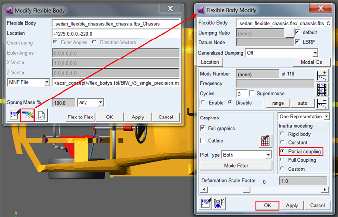
12. Next modify the car body to be treated flexibly throughout the analysis:
a. Right-click - Modify
b. From the flexible beam icon open the detailed Flexible Body Modify dialog box from the icon
c. Set Inertia Modeling to "Partial coupling" and click OK.
13. Re-run the same event this time using the Output Prefix "flex"
14. When it completes note the CPU time consumed which will naturally be much higher than the rigid body run.
Note: | Your time will most likely differ from what's shown below due to environment differences. |
15. Now modify the body to be a "dual representation" body that starts rigid and can be converted to a flexible representation during runtime:
a. Right-click - Modify
b. From the flexible beam icon open the detailed Flexible Body Modify dialog from the icon
c. Select "Dual Rep Start Rigid" from the menu above Inertia Modeling
d. Click OK
16. Next you need to create an analysis in which you will instruct Adams Solver to switch the representation of the body from rigid to flexible just prior to hitting the pothole:
a. Open the File Driven Events dialog box again
b. Use "hybrid" for the Output Prefix
c. Set Simulation Mode to "files_only" to simply generate the .adm, .acf and other files required but not actually run the analysis
d. Click OK
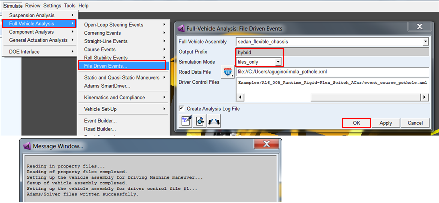
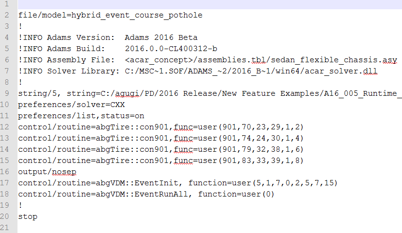
17. The files will be written to your working directory. Browse and open the "hybrid_event_course_pothole.acf" in a text editor:
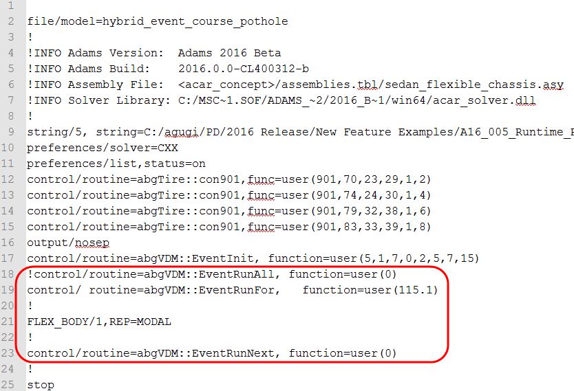
18. The Adams Solver FLEX_BODY command has been updated in this release with the argument REPRESENTATION which can be set to either RIGID or MODAL. In this case you need to switch the flexible body at time=115.1sec to be MODAL. So, make the changes shown below and save the file (You can also copy these changes from the file "hybrid_event_course_pothole_completed.acf" which you copied to your working directory in the first step of this tutorial.
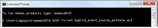
19. Launch the hybrid run in standalone Adams Car Solver:
a. Open the "Adams Command Prompt" via (on Windows) Start Menu → All Programs - Adams 20XX → Command Prompt
b. Change directory to your working directory via the "cd" command (for example, "cd C:\Adams\MyWorkDir")
c. Run the analysis via the command:
adams20XX acar ru-solver hybrid_event_course_pothole.acf (where XX represents the current installed version)
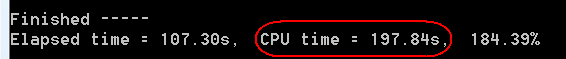
20. When the analysis completes note the CPU time. It should be longer than the rigid-only run but shorter than the flexible-only run (possibly even shorter than the rigid run since running in standalone Adams Solver can help performance slightly):
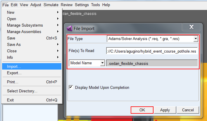
21. Import this analysis into the Adams Car session already containing the "rigid" and "flex" analyses:
22. Open Adams PostProcessor by pressing the F8 Key or via Review → Postprocessing Window
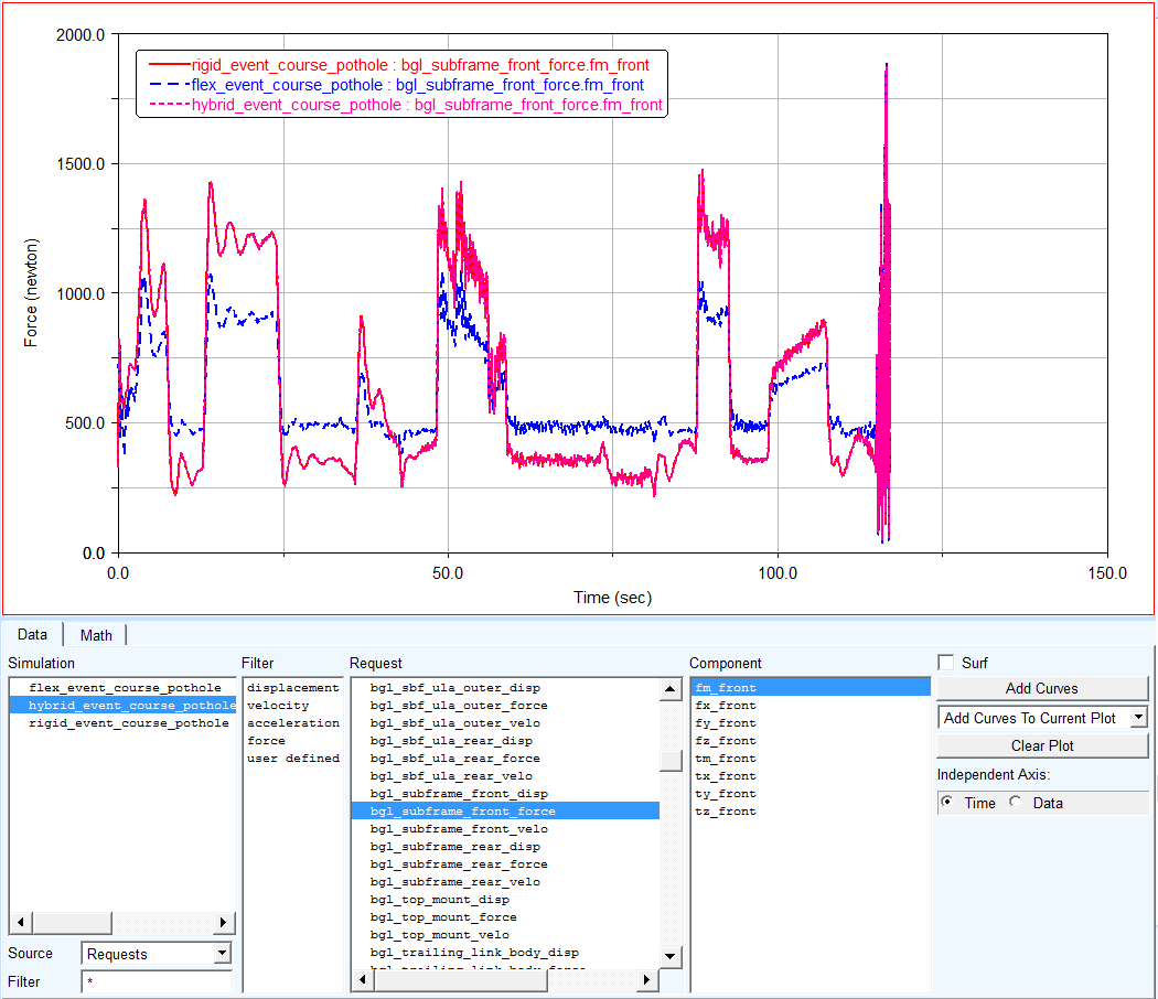
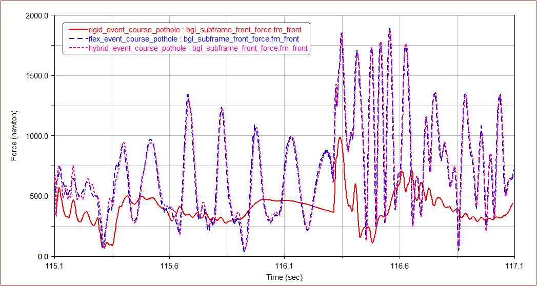
23. Examine some results, such as one of the subframe to body bushings (shown below) to see that the hybrid run matches closely the rigid results initially and then during the pothole collision matches the flexible body results more closely. Zooming in, some differences are noticeable especially just after the switch. The result comparison will not be line-on-line since the two runs have essentially different initial conditions. Remember, the hybrid run treated the body rigidly until just before the pothole.