External
The Adams Machinery Motor module provides for the modeling of motor systems within the Adams View environment. It supports multiple modeling methodology options including an external modeling method. This example shows how to create a motor using the external method from the minimal set of input parameters.
This chapter includes the following sections:
What You Will Create
You will model a motor consisting of two parts (Stator and Rotor) with simple geometry. The stator and rotor will be attached to the ground and crank (Input) respectively. The crank is connected with a revolute joint and a spherical joint to the ground and connecting rod respectively. The connecting rod is connected to the rocker via a universal joint. The rocker is connected to ground via a revolute joint. The crank will be driven by a prescribed torque provided via ESL (External System Library, which is a binary representation of model generated by MATLAB®) and the simulation will be carried out entirely inside Adams. The torque created in the motor will be based on this external model.
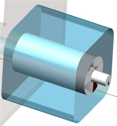
Figure 3 Motor Model
External Method Motor Model
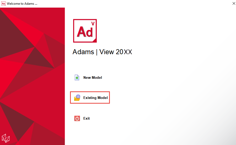
1. Start Adams 2024.1 → Adams View.
2. From the welcome screen click Existing Model.
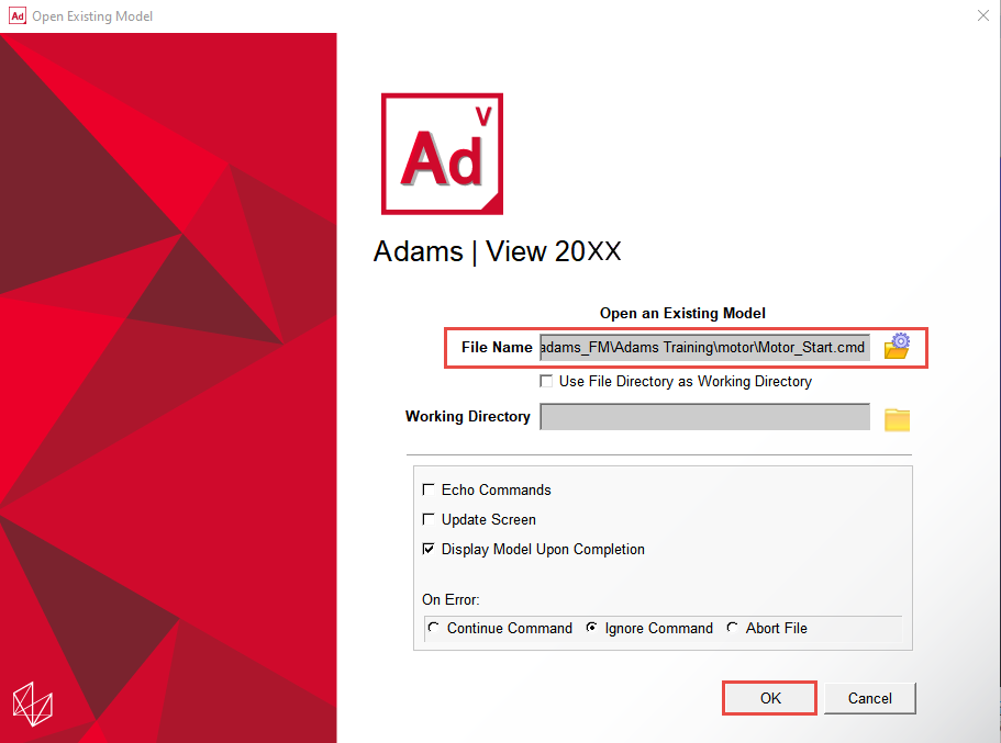
3. Open the model Motor_Start.cmd from the installation directory. For example, Windows examples files placed in the below location:
C:\Program Files\MSC.Software\Adams\2024_1\amachinery\example\motor\Motor_Start.cmd.
C:\Program Files\MSC.Software\Adams\2024_1\amachinery\example\motor\Motor_Start.cmd.
Tip: | Copy the example files folder and place it outside the working directory. Doing this, you can avoid having the working directory inside the Adams install folders. |
4. The imported model will look like the one shown below.
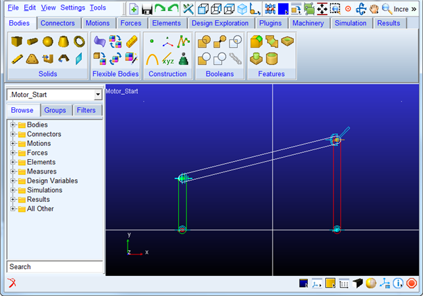
a. It has:
♦Crank geometry connected with revolute and spherical joint with ground and connecting rod
♦Connecting rod is connected to rocker with universal joint
♦Rocker is connected to ground with revolute joint
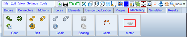
5. Click the Machinery tab on the Adams View ribbon.
6. From the Motor container, click the icon for Create Motor icon.
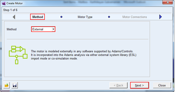
7. The motor creation wizard will launch. On the first page (Method) select External from the Method option menu and click Next.
Note: | After selecting the Method as External, a Question window will appear prompting you to load the CONTROLS plugin. Click Yes. |
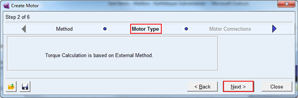
8. On the next page (Motor Type) click Next to proceed.
9. On the next page (Connection) enter values for as given below (circled in Red) and click Next.
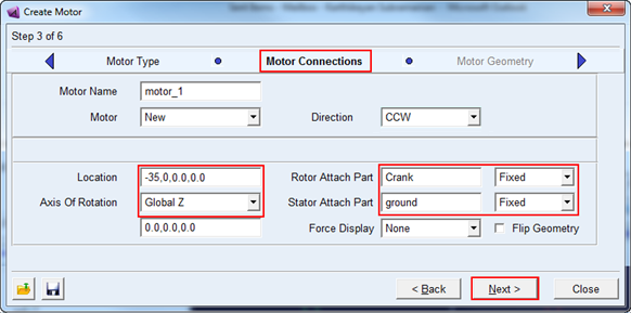
a. Enter the values for the following fields and accept the defaults for others as shown below
♦Axis of Rotation as “Global Z”.
♦Enter the values “-35.0,0.0,0.0” in mm for location.
♦Rotor attach part as “Crank” from right-mouse-button option Guesses.
♦Stator attach part as “ground” from right-mouse-button option Guesses.
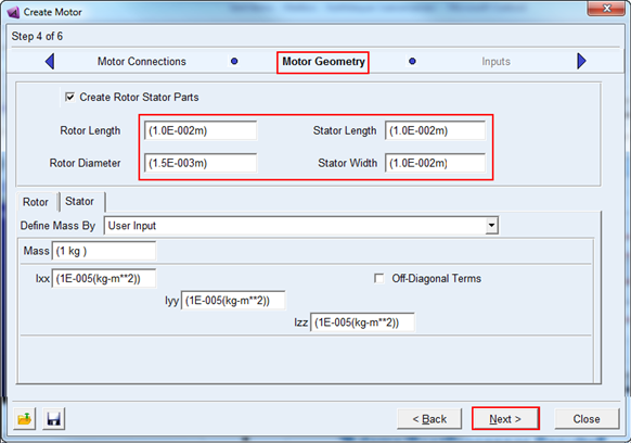
10. In the Motor Geometry, enter the values (circled in red) as shown below and accept the default values for others and click Next.
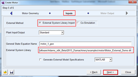
11. In the Inputs page select External System Library Import option and select the Motor_External_Demo.dll created by MATLAB® via the right-mouse-button option from GUI as shown below. Click Next.
Important: | Please select the .dll based on your platform. The .dll is different for all three platforms. |
Tip: | Copy the .dll file Motor_Start_DLL\<OS>\motor_external_<os>.dll to working directory. Doing this, you can avoid having the working directory inside the Adams install folders. |
Simulation
Simulate your model for 1 second at 1000 steps by clicking the Interactive Simulation icon from the Simulate container on the Simulation tab, entering the values shown below and clicking the Start Simulation button.
Note: | Ensure Executable is set to Internal. To do so, click on Simulation Settings on the Simulation Controls window and set Executable to Internal. |
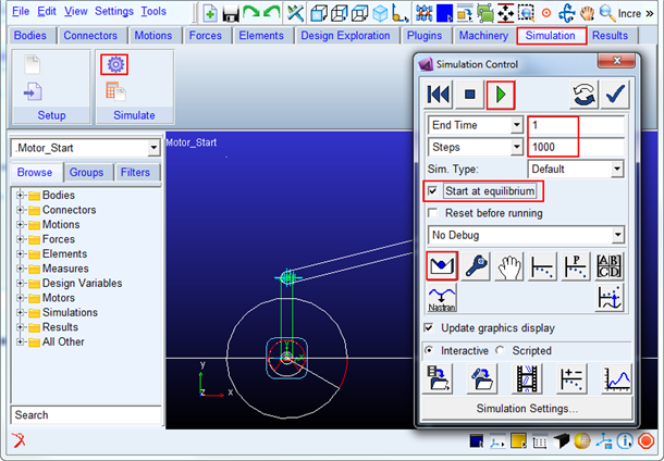
a. Before running the simulation, do the following steps in the order mentioned below:
■Check the Start at equilibrium
■Click the Find Static Equilibrium
■Now run the simulation by clicking Start Simulation Button
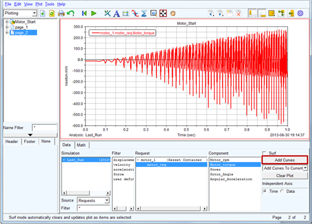
Adams PostProcessor Results
1. Switch to PostProcessor by clicking plotting icon from the Simulation Control.
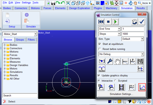
2. In the Post Processor, Select the items highlighted in blue and then by clicking Add Curves button to plot the torque transmitted.