Creating an Electric Motor
During this tutorial, you will define an electric motor model. You prepare magnetic force excitation for rotor and stator parts along with flexible parts representation for rotor and stator with simplified housing.
The model is loaded with rigidized flexible parts, you will replace those with created flexible parts from preprocessing step. In addition, you create measurement point on housing to evaluate the acceleration on housing surface. After preprocessing you will create electromagnetic force acting between stator and rotor. Finally, you execute a simulation and investigate the results.
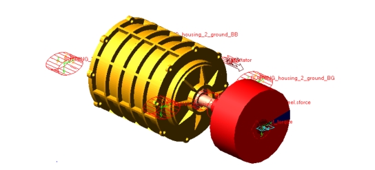
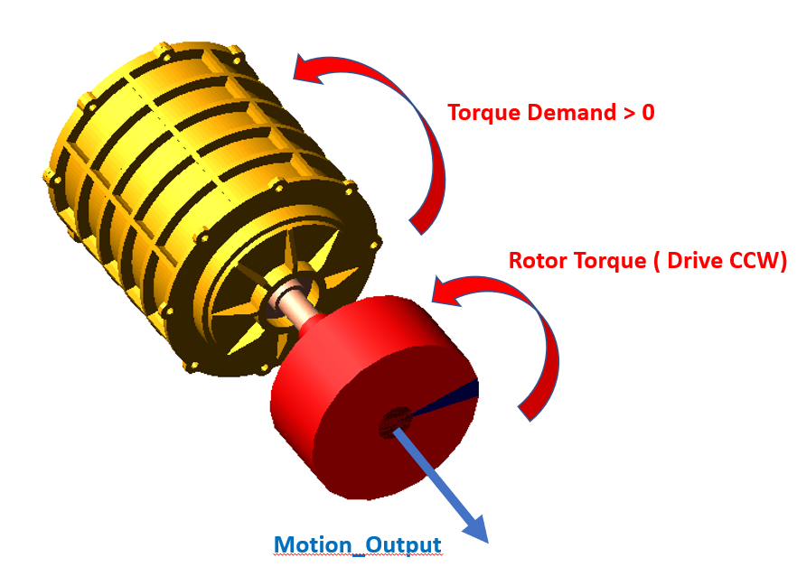
Figure 1 shows an electric motor that you are going to create.
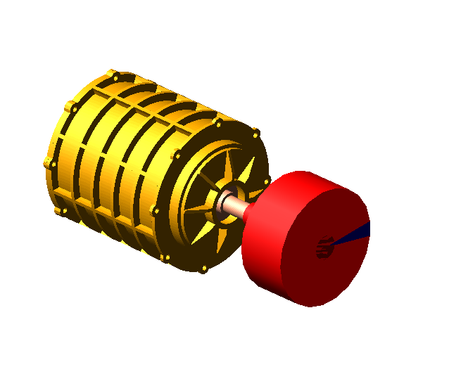
Figure 1 Electric Motor
Prepare Your Working Directory and Start Adams View
To prepare your working directory:
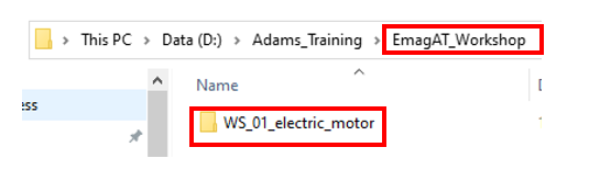
1. Create new directory named WS_01_electric_motor, which will be your working directory for Adams View session and will include all motor model related files.
2. Start Adams either from desktop or Windows Start → Adams 20XX.
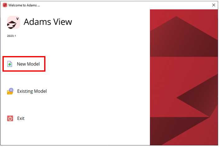
3. In the Welcome to Adams dialog box, select New Model.
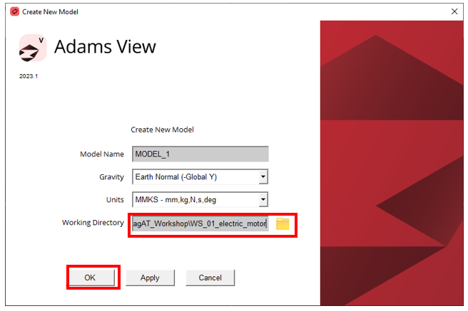
4. Set the Working Directory to WS_01_electric_motor directory.
5. Click the OK button.
Load the Workshop Model
To load the workshop model:
1. Click the Machinery tab on the Adams View ribbon and from the Motor container, click the icon to pop up Emag AT menu.
2. In the Emag AT menu, select Help → Getting started → Workshop Start Model.
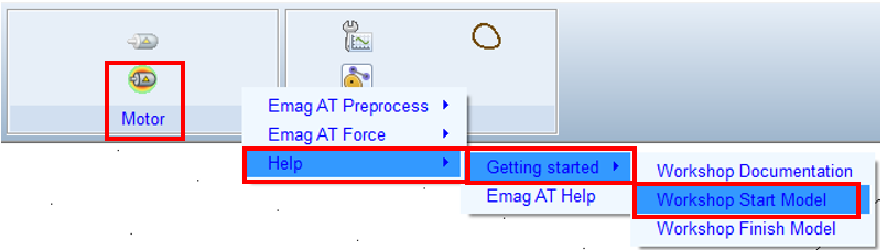
The starting workshop model emag_at_model gets loaded.
Create Harmonic files
At this point there are no harmonic files (*.EMH) available, so you have to prepare them from scratch. In this step you transform magnetic force density files in time domain (*.TAB) to frequency domain and create those data for all operation quadrants of the motor DCCW, BCCW, DCW, BCW.
To Create Harmonic files:
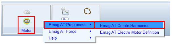
1. In the Emag AT menu, select Emag AT Preprocess → Emag AT Create Harmonics.
2. Copy and unzip force data from:
Adams_instalation\emag_at\examples\permanent_magnet_motor\magnetic_force\
in to:
Working directory\source_emag_tab
Adams_instalation\emag_at\examples\permanent_magnet_motor\magnetic_force\
in to:
Working directory\source_emag_tab
3. Prepare results directory:
Working directory\results_emh
Working directory\results_emh
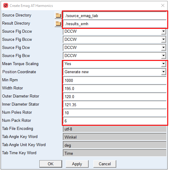
4. In the Dialog box select the Source Directory and Result Directory.
5. Select Mean Torque Scaling to: Yes
6. Select Position Coordinate to: Generate new
7. Set Min Rpm to: 1000
8. Set Width Rotor to: 195.0
9. Set Outer Diameter Rotor to: 120.0
10. Set Inner Diameter Stator to: 121.35
11. Set Num Poles Rotor to: 10
12. Set Num Pack Rotor to: 6
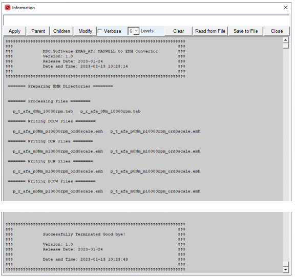
The convertor transforms force data from time domain into frequency domain by use of Fourier transform. This is done for each operation point file (*.tab) in the source directory. In addition, the source data is populated for all operation quadrants of motor. The progress is reported into the information window as well as in a log file. Upon successful conversion process there will be number of *.EMH (Electro Motor Harmonic) files written in the Working directory\results_emh sub directory, which will be further processed in the next step.
Create Electromagnetic Force File
The Electromagnetic force file (*.EMF) defines excitation on rotor and stator components of electric motor and is created during the pre-processing step. The starting point for Emag AT preprocessing is to create motor property file ( *.EMP), where all required motor parameters are summarized. In addition, it references all required input data for excitation force and definition of rotor and stator (housing) structures. The property file is automatically written to store your input for later use.
To Create electromagnetic force file:
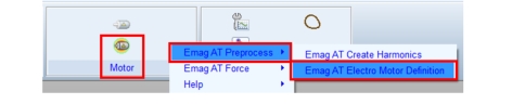
1. In the Machinery ribbon go to Motor container and expand the Emag AT menu, select Emag AT Preprocess → Emag AT Electro Motor Definition.
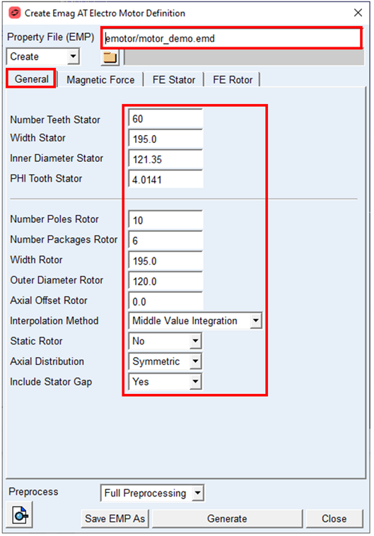
2. Type in the Property File name with relative path: ./emotor/motor_demo
3. In the General tab, enter Number Teeth Stator: 60
4. Set the value in Width Stator to: 195.0
5. Set the value in Inner Diameter Stator to: 120.35
6. Set the value in PHI Tooth Stator: 4.0141
7. Set the value in Number Poles Rotor to: 10
8. Set the value in Number Packages Rotor to: 6
9. Set the value in Width Rotor to: 195.0
10. Set the value in Outer Diameter Rotor to: 120.0
11. Set the Interpolation Method to: Middle Value Integration
12. Set the Static Rotor: No
13. Set the Axial Distribution: Symmetric
14. Set the Include Stator Gap: Yes
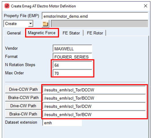
15. In the Magnetic Force tab, set N Rotational Steps to: 64
16. Set the value in Max Order to: 70.0
17. Set the Full path to DCCW folder under created Emh files, use Drive CCW Path and point to:
Working Directory\results_emh\scl_Tor\DCCW
Working Directory\results_emh\scl_Tor\DCCW
18. Set the Full path to BCCW folder under created Emh files, use Brake CCW Path and point to:
Working Directory\results_emh\scl_Tor\BCCW
Working Directory\results_emh\scl_Tor\BCCW
19. Set the Full path to DCW folder under created Emh files, use Drive CW Path and point to:
Working Directory\results_emh\scl_Tor\DCW
Working Directory\results_emh\scl_Tor\DCW
20. Set the Full path to BCW folder under created Emh files, use Brake CW Path and point to:
Working Directory\results_emh\scl_Tor\BCW
Working Directory\results_emh\scl_Tor\BCW
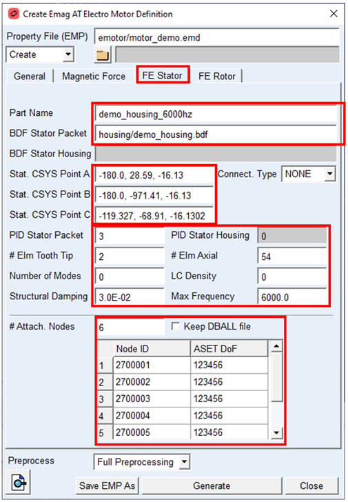
21. In the FE Stator tab, set Part Name to: demo_housing_6000hz.
22. Browse to BDF file defining Housing and stator in BDF Stator Packet to:
./housing/demo_housing.bdf
./housing/demo_housing.bdf
23. Set the vector value for Stat. CSYS Point A to: -180.0, 28.59, -16.13
24. Set the vector value for Stat. CSYS Point B to: -180.0, -971.41, -16.13
25. Set the vector value for Stat. CSYS Point C to: -119.327, -68.91, -16.1302
26. Set the value PID Stator Packet to: 3
27. Set the value # Elem Tooth Tip to: 2
28. Set the value Structural Damping to: 0.03
29. Set the value # Elm Axial to: 54
30. Set the value Max Frequency to: 6000
31. Set the value # Attach. Nodes to: 6
32. In the node table set Node ID to: 2700001 till 2700006 and ASET Dof for each Node to: 123456
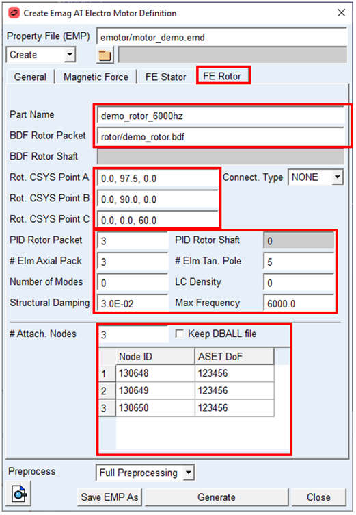
33. In the FE Rotor tab, set Part Name to: demo_rotor_6000hz
34. Browse to BDF file defining rotor in BDF Rotor Packet to:
./rotor/demo_rotor.bdf
./rotor/demo_rotor.bdf
35. Set the vector value for Rot. CSYS Point A to: 0.0, 97.5, 0.0
36. Set the vector value for Rot. CSYS Point B to: 0.0, 90.0, 0.0
37. Set the vector value for Rot. CSYS Point C to: 0.0, 0.0, 60.0
38. Set the value PID Rotor Packet to: 3
39. Set the value # Elem Axial Pack to: 3
40. Set the value Structural Damping to: 0.03
41. Set the value # Elm Tan. Pole to: 5
42. Set the value Max Frequency to: 6000
43. Set the value # Attach. Nodes to: 3
44. In the node table set Node ID to: 130648 till 130650 and ASET Dof for each Node to: 123456
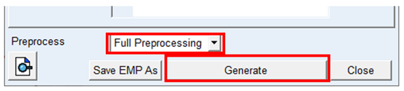
45. Set the Preprocess option menu to Full Preprocessing
46. Start the preprocessing by pushing Generate button, and please wait for several minutes to complete.
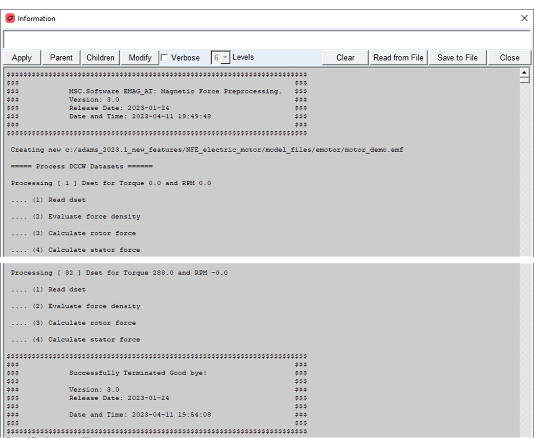
The preprocessing will start with magnetic force evaluation for each rotation step, then the stator and finally the rotor structure is processed. The result of the preprocessing is electromagnetic force file (*.EMF), which includes excitation nodal forces for stator and rotor as well as modal shape vectors for surface grids on rotor and stator flexible body structure. In addition, the Nastran SOL103 is executed to generate MNF files for rotor and stator FE structures.
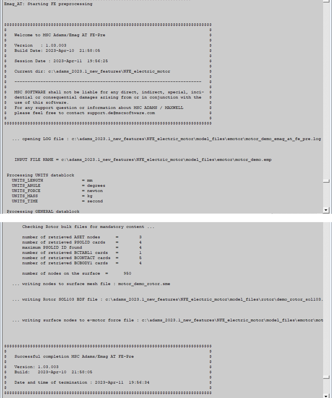
The progress is reported in the information window as well as in log files, it consists of following steps:
1. Magnetic Force Preprocessing:
♦The new *.EMF file is written in the same sub directory as *.EMP property file, which will be used by e-motor force during simulation
2. Rotor and stator FE preprocessing:
♦appends data to the *.EMF file
♦writes Nastran input decks for rotor and stator SOL103 in ./model_files/housing and ./model_files/rotor sub directory, respectively to produce MNF files in subsequent step
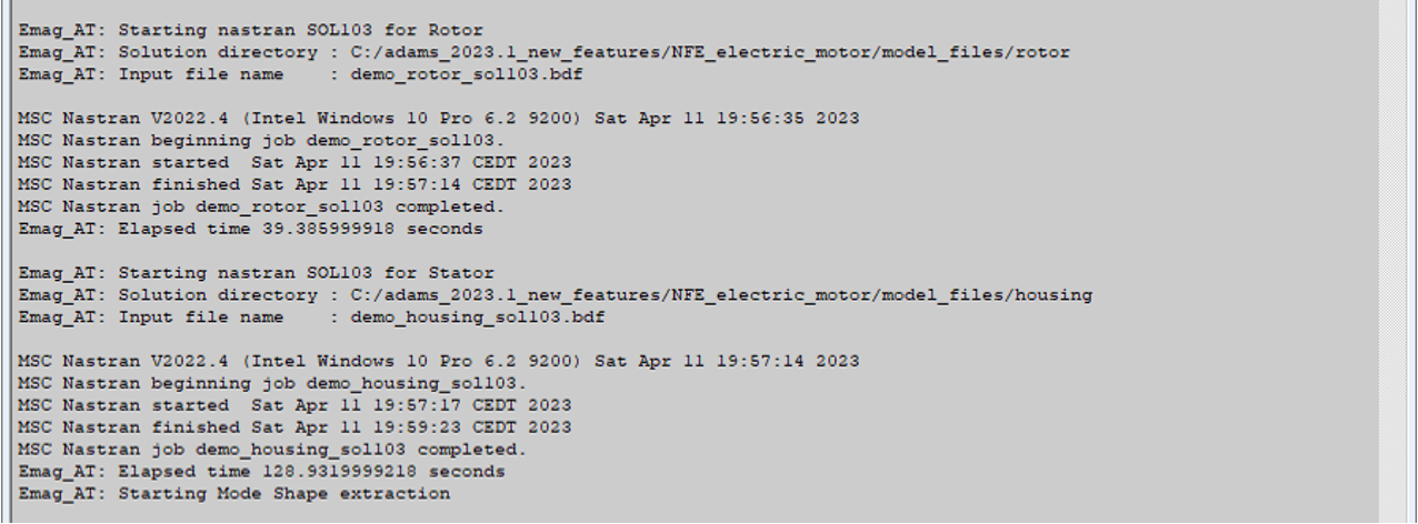
3. Rotor and stator MNF generation by Nastran SOL103 (or by ViewFlex):
■new MNF files are written in ./model_files/housing and ./model_files/rotor sub directory, respectively
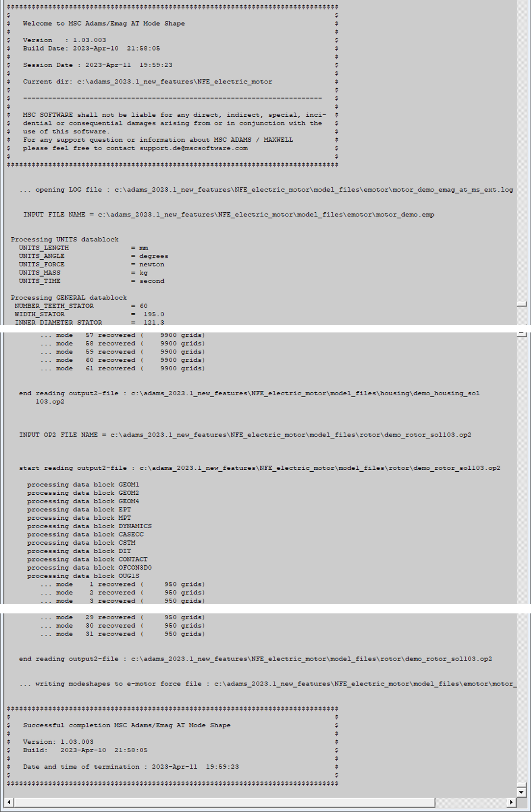
4. Mode shape extraction for rotor and stator surface nodes:
♦appends data to the *.EMF file
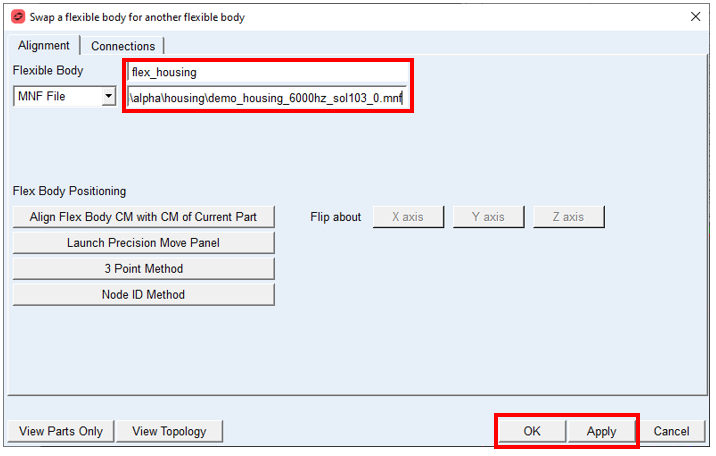
Swap rigid MNF’s for flexible MNF’s
The model is loaded with rigid flexible parts, to enable the flexibility we will swap MNF files for flex_rotor and flex_housing parts with ones just created with the preprocessing step.
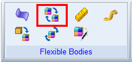
1. Open the Flex to Flex tool in Main ribbon
2. Select Flexible Body: flex_housing
3. Browse for created mnf to: housing/demo_housing_6000hz_sol103_0.mnf
4. Apply changes.
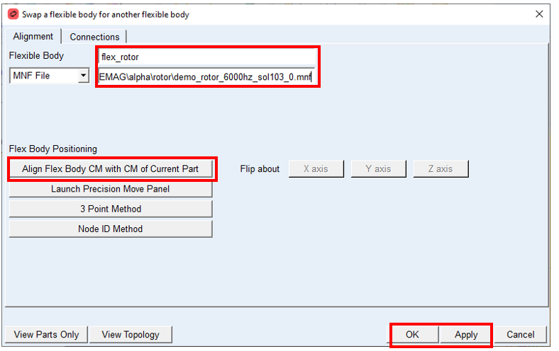
5. Select Flexible Body: flex_rotor
6. Browse for created mnf to: rotor/demo_rotor_6000hz_sol103_0.mnf
7. Align the position of rotor based on CM location.
8. Apply changes.
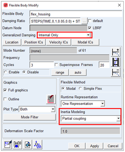
9. Open modify dialog box for flex_rotor and flex_housing
Modify flex_housing and flex_rotor parts
1. Set Inertia Modeling to: Partial Coupling
2. Set Generalised Damping to: Internal Only
Create Emag AT Electromagnetic Force
The electromagnetic force applies load generated by magnetic field on the stator and rotor surface enclosing the air gap between those two parts. Before creating the electromagnetic force, you need to define a reference marker on both, rotor and stator flexible part, which is used to calculate the relative motion between those two parts.
Note: | The Z axis of reference marker should be aligned with rotation axis of rotor, pointing to motor power output side, and located in the mid-span of the rotor / stator packet width. |
To Create reference marker on rotor and stator
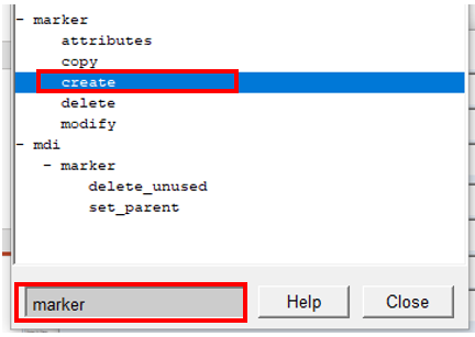
1. From the Tools menu open Command Navigator and search for marker.
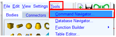
2. Double click on Marker/ Create command.
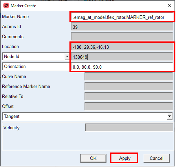
3. In the Marker Create Dialog box edit the marker name to: .emag_at_model.flex_rotor.MARKER_ref_rotor
4. Set the Location to: -180.0, 29.36, -16.13
5. Set the Node ID to: 130649
6. Set the Orientation to: 0.0, 90.0, 90.0
7. Apply changes.
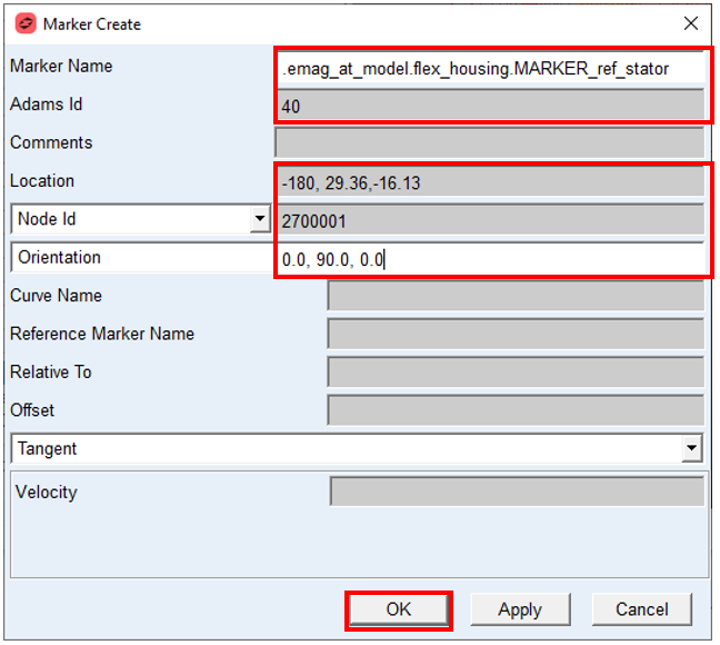
8. In the Marker Create Dialog box edit the Marker Name to: .emag_at_model.flex_housing.MARKER_ref_stator
9. Increase the value of Adams Id by 1
10. Set the Location to: -180.0, 29.36, -16.13
11. Set the Node ID to: 2700001
12. Set the Orientation to: 0.0, 90.0, 0.0
13. Apply changes.
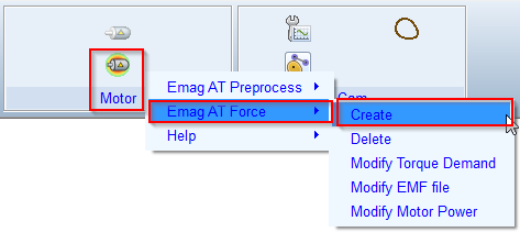
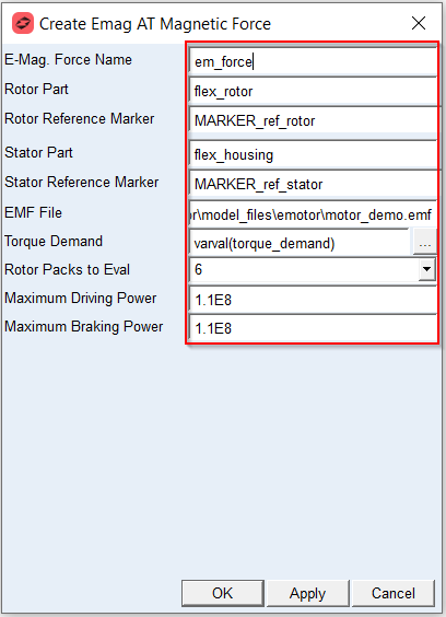
To Create Emag AT Electromagnetic Force
1. In the Emag AT menu, select Emag AT Force → Create
2. Enter the E-Mag. Force Name: em_force
3. For Rotor Part, Right click → Flexible Body → Browse and select flex_rotor
4. For Rotor Reference Marker, Right click → Marker → Browse and select flex_rotor.Marker_ref_rotor
5. For Stator Part, Right click → Flexible Body → Browse and select flex_housing
6. For Stator Reference Marker, Right click → Marker → Browse and select flex_housing.Marker_ref_stator
7. Right click and Browse for the EMF File in the ./emotor directory :motor_demo.emf
8. Set the Torque Demand to varval(torque_demand)
9. Set the number Rotor Packs to Eval in requestes to: 6
10. Set value of Maximum Driving Power parameter to 1.1E08 ; in model units [milliWatts]
11. Set value of Maximum Braking Power parameter to 1.1E08 ; in model units [milliWatts]
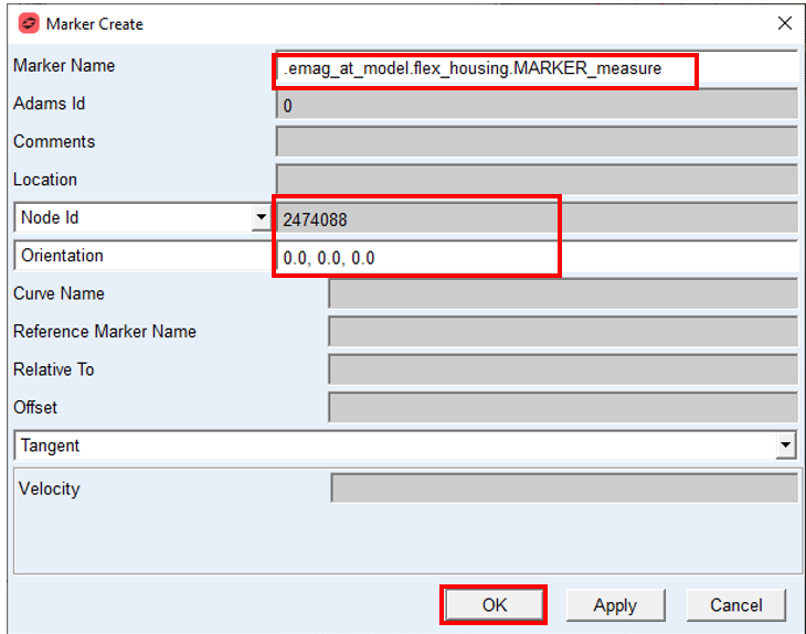
Create acceleration measure on motor housing
1. From the Tools menu open Command Navigator and search for marker.
2. Double click on Marker/ Create command.
3. In the Marker Create Dialog box edit the Marker Name to: .emag_at_model.flex_housing.MARKER_measure
4. Set the Node ID to: 2474088
5. Set the Orientation to: 0.0, 0.0, 0.0
6. Apply by OK
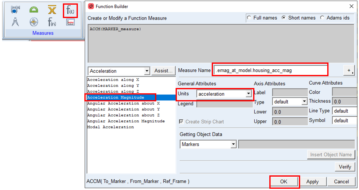
7. From the main ribbon select: Create Function Measure
8. Select function Acceleration Magnitude and with Assistant wizard select the To Marker to MARKER_measure
9. Adjust Measure Name to: .emag_at_model.housing_acc_mag
10. Adjust Units to: acceleration
11. Apply by OK
Setup Output Motion and Torque Demand
To set Output motion and Torque Demand:
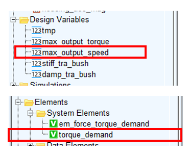
1. Modify Design Variable max_output_speed, set the value to 3000
2. Modify Adams System Variable torque demand to apply 75 Nm, set the expression to:
75e3*step5(time, 0.0,0.1,0.25,1.0).
75e3*step5(time, 0.0,0.1,0.25,1.0).
Verify the solver settings
To set the solver settings:
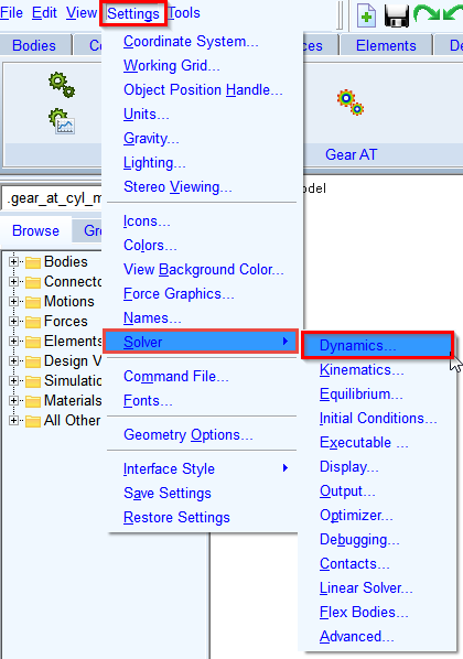
1. In the Settings menu, select Solver → Dynamics
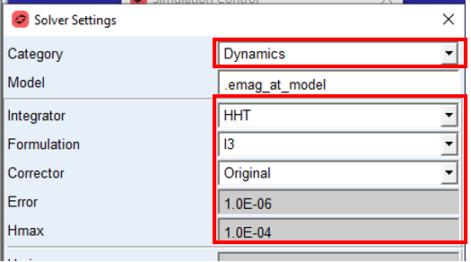
2. Select Category: Dynamics
3. Select the Integrator: HHT.
4. Set the value of Error: 1.0E-006
5. Set the value of Hmax: 1.0E-004
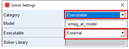
6. Change the Category to: Executable.
7. Set the Executable to: External.
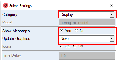
8. Change the Category to: Display.
9. Set the Show Messages to: Yes.
10. Set Update Graphics to: Never
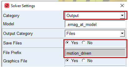
11. Select Category: Output.
12. Set the Save Files: Yes.
13. Set the File Prefix: motion_driven.
Verify Simulation script and run the Simulation
To verify the simulation script and run the dynamic simulation:
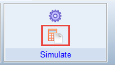
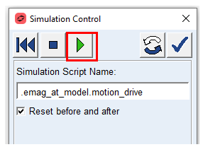
1. In the Simulation tab select Run a Scripted Simulation.
2. Right click in Simulation Script Name, select Simulation_Script → Guesses → motion_drive.
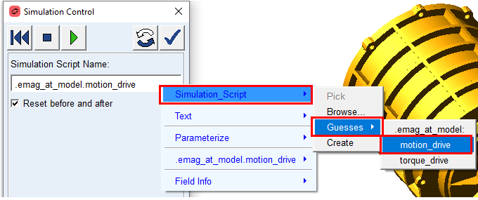
3. Right click in Simulation Script Name, select .emag_at_model.motion_drive → Modify
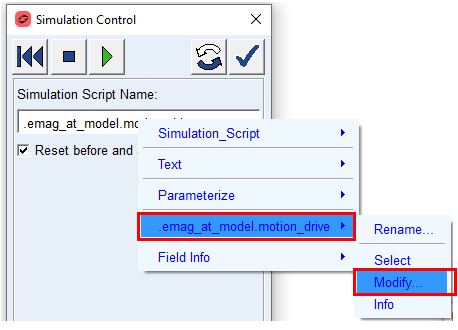
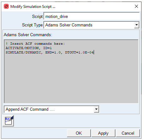
4. Start simulation
Investigate the Simulation Results
In the Adams Postprocessor investigate the simulation results. Select Page Layout: 2 Views, side by side.
Make a plot of Torque Demand and Rotor_wz_rpm vs time:
1. Switch to Adams Postprocessor by pressing F8 on keyboard.
2. Select the Source: Requests.
3. Select the Request: em_force_Operation_Point.
4. Select the Components: Rotor_wz_rpm and click Add Curves button to right plot.
5. Select the Components: Torque_demand and click Add Curves button to left plot.
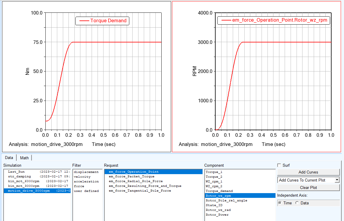
As you can see, the rotor RPM is controlled by the motion to hold steady state 3000 RPM while the Torque Demand is ramped to 75 Nm.
Next, you will investigate rotor torque and measured acceleration signal measured on housing surface.
1. Create a new page and select the Source: Requests.
2. Select the Request: em_force_Resulting_Force_and_Torque.
3. Select the Components: Rotor_Tz and click Add Curves.
4. In the main menu bar, expand Plot menu and select FFT tool and create FFT plot out of the rotor torque signal in time range 0.3 to 1.0 sec
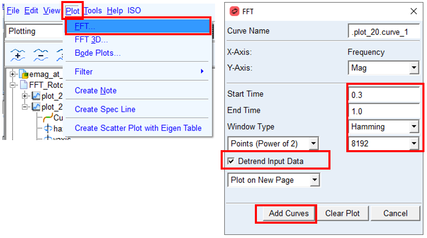
5. Make sure the Detrend Input data is checked
6. Select Add Curves
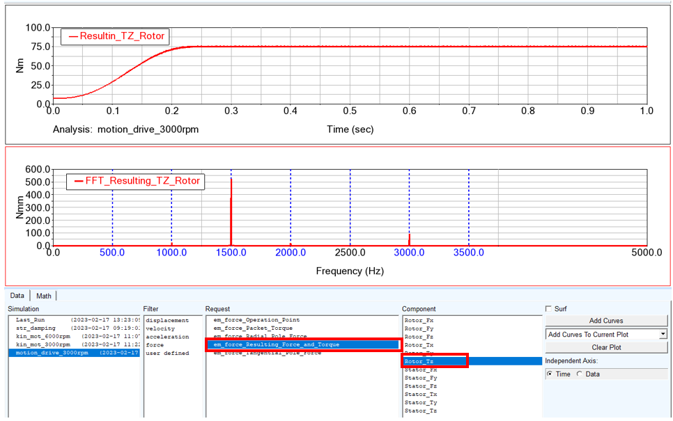
The input data in *.EMH files contains selected motor orders, in this case 0, 10, 20, 30, …, 70. This means that in the rotor signal one should observe in the rotor signal mainly frequencies corresponding to these orders. Considering the rotor speed (frequency of rotation is 50 Hz), one gets the rotor orders at 500Hz, 1000Hz, 1500Hz, …. As you can see from the results this applies for the FFT analysis of the rotor torque.
Lastly, you will investigate acceleration signal measured on flexible housing surface.
1. Create new page and select the Source: Measures.
2. Select the Measure: housing_acc_mag.
3. In the main menu bar, expand Plot menu and select FFT tool and create FFT plot out of the acceleration signal in time range 0.3 to 1.0 sec
4. Make sure the Detrend Input data is checked
5. Select Add Curves
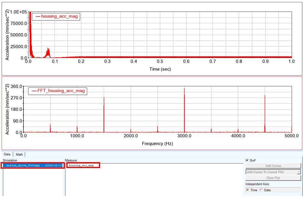
As you can see, similarly to previous analysis, there are the main motor orders present in the housing surface acceleration signal.
Save your Work
To save your model:
1. Switch to Adams View by pressing F8 on keyboard.
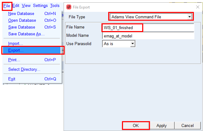
2. In the File menu, select Export...
3. Select the File Type: Adams View Command File.
4. Enter File Name as WS_01_finished.
5. Click the OK button.
The CMD file is exported.
The CMD file is exported.