Creating Cam Model
Steps for Running Example
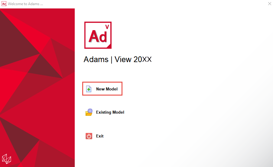
1. Start Adams 2024.1 → Adams View.
2. From the welcome screen click New Model.
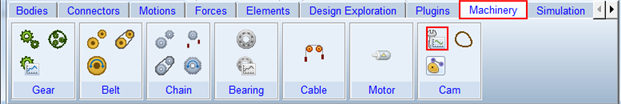
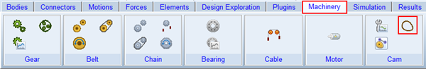
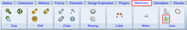
3. Click the “Machinery” tab on the Adams View Ribbon.
Define Desired Follower Motion
4. From the Cam container, click the icon for the Follower Motion builder.
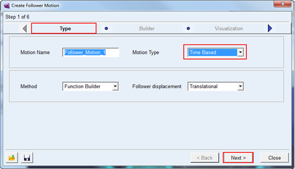
5. The follower motion creation wizard will launch. On the first page (Follower Motion) select Time Based option for motion type and accept default values for others. Click Next.
6. On the second page (Builder) select function type STEP and click Next by accepting default values. You could optionally preview the entered values as a plot by clicking Plot button in the right side end.
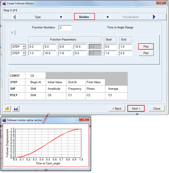
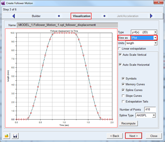
7. In the Visualization page preview the follower motion (Displacement vs Time) by selecting Plot for view as option as shown below. You could select the spline type to AKISPL or CUBSPL but for this example accept the default values and click Next.
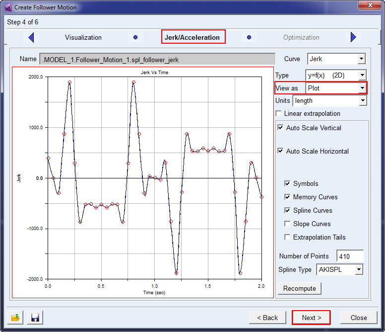
8. In the Jerk/Acceleration page preview the follower motion (Jerk/Acceleration vs Time) by selecting Plot for view as option as shown below. Accept the default values and click Next.
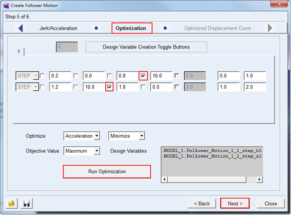
9. The Optimization page allows the user to specify acceptable ranges for key parameters of the functions and desired target. You could select all or few of these design variables as parameters for optimization.
a. For this example select/check the parameters as shown below from the check boxes. This creates design variables which can be used for the optimization.
b. The design variables will be automatically populated for use as factors in the optimization: Follower_Motion_1_1_step_h1 and Follower_Motion_1_2_step_x1.
Note: | By default these design variables are built with a range of +/- 10% of the nominal value. One can modify the acceptable range by modification of these design variable objects. |
c. Click Run Optimization to start the optimization process.
10. Click Next and the optimized curve is displayed in the Optimized Displacement Curve page. Click Finish to complete the follower motion creation.
11. Click Finish to accept this optimized follower displacement curve.
Derive Cam Profile
12. From the Cam container, click Cam Profile create icon.
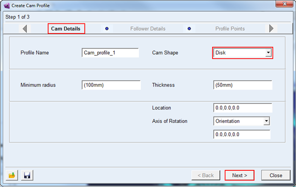
13. In the Cam Details page, select Disk cam shape option and accept the default values and click Finish.
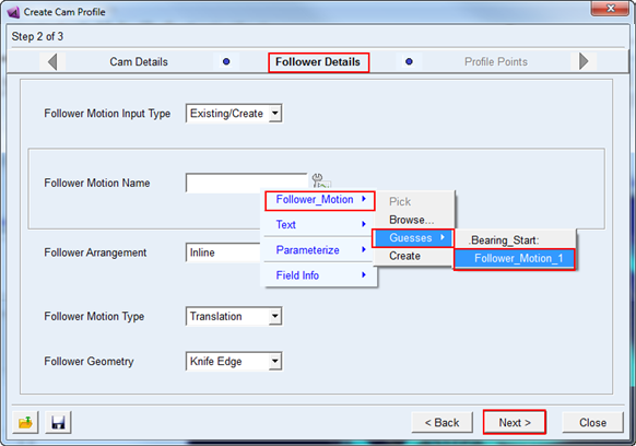
14. In the Follower Details page, select Follower_Motion_1 for follower motion name from right-mouse click guesses option as shown below. Accept the default values for others and click Next.
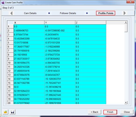
15. In the Profile Points page, X,Y and Z coordinates of cam profile are displayed as shown below. Click Finish button to complete the cam profile creation.
Note: | If a warning message appears regarding a missing .shl file, this can be ignored; it is a known issue and will be addressed in the final release. |
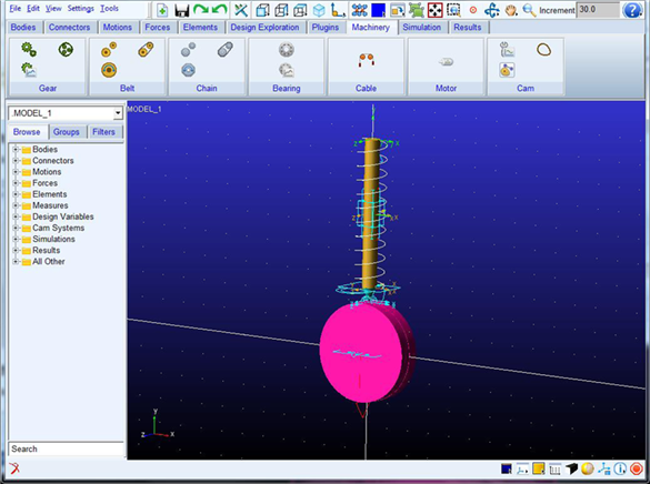
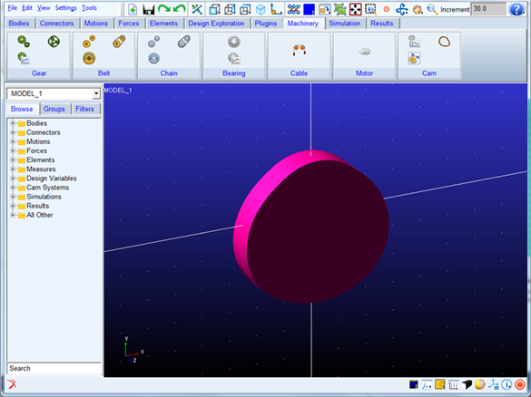
16. The following Cam profile will be generated:
Cam-Follower System Creation
17. Now create a cam system by clicking Cam System create icon.
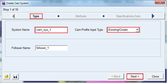
18. In the first page (Type) select Existing/Create option for Cam profile input types. Accept the default values for others and click Next.
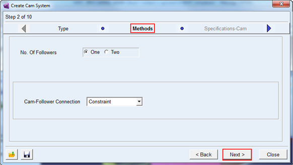
19. In the Methods page, you will select number of followers and connection between cam and follower. For this example accept the default values and click Next.
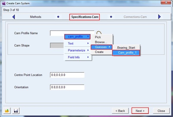
20. In the Specifications-Cam page, select Cam_profile_1 for Cam profile name by right-mouse click guesses option as shown below. Accept the default values for others and click Next.
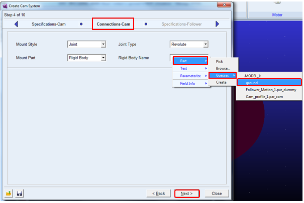
21. In the Connection-Cam page, Select ground by right-mouse click guesses option as shown below to connect cam via revolute joint with ground. Accept the default values for others and click Next.
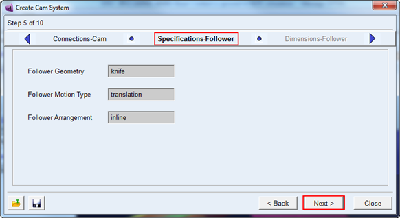
22. Confirm the follower specification details selected in the step 13 above in the Specifications-Follower page. Click Next.
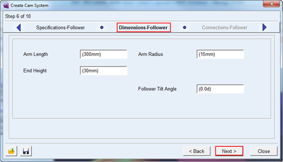
23. Enter the dimensions for follower in the Dimensions-Follower page. For this example accept the default values and click Next.
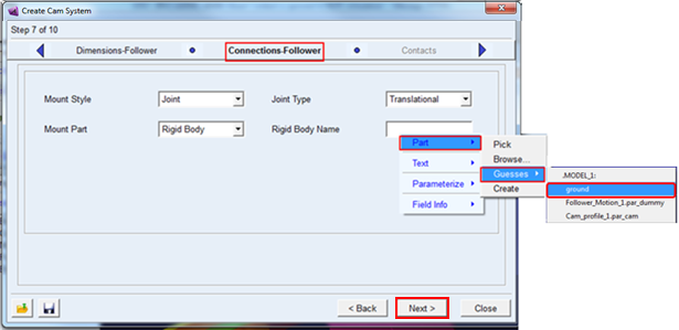
24. In the Connections-Follower page, select ground by right-mouse click Guesses option as shown below to connect follower via translational joint with ground. Accept the default values for others and click Next.
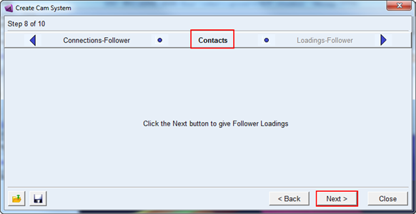
25. You will enter the contact properties foe Cam-Follower here for connection type Contact. Here the page is blank as “Constraints” option is selected for connection. Click Next.
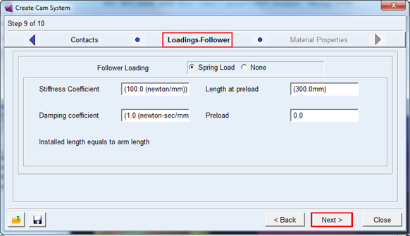
26. Accept the default values for Loading-Follower to create translational spring damping force element and click Next.
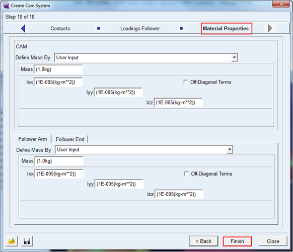
27. In the Material Properties page, enter the mass and inertia properties for cam and follower. For this example accept the default values and click Finish to complete cam system creation.
28. The created cam system will look like the one shown below.