Creating a Ball and Roller Bearing
Prepare your working directory
To prepare your working directory:
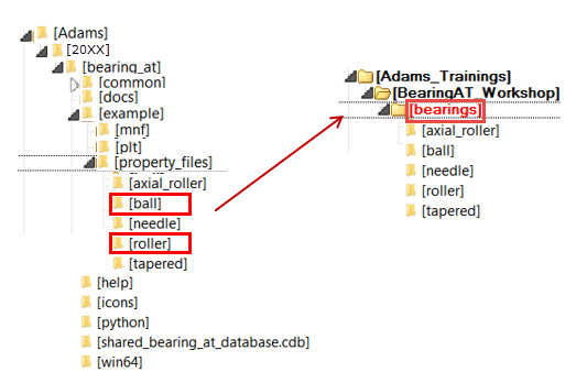
1. Navigate to your working directory (in this document it is BearingAT_Workshop), in which you create new directory named as bearings to store all files related to bearings.
2. Find the property_files directory in the Bearing AT installation.
3. From property_files directory select ball and roller folders and copy it to the BearingAT_Workshop/bearings directory.
Start Adams View
To load a Bearing AT plugin:
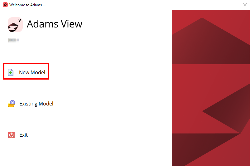
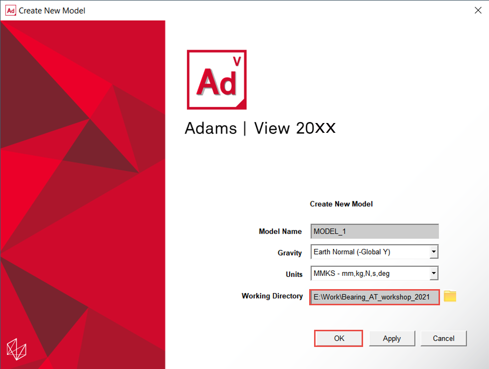
1. Under the Welcome dialog box, select New Model.
2. Set the Working Directory as BearingAT_Workshop.
3. Click the OK button.
Load the Workshop Model
To load the workshop model:
1. Click the Machinery tab on the Adams View ribbon and from the Bearing container, click the icon to pop up Bearing AT menu.
2. In the Bearing AT menu, select Test Models → Start Model.
.png)
3. The tutorial model start_model_bearing will be loaded.
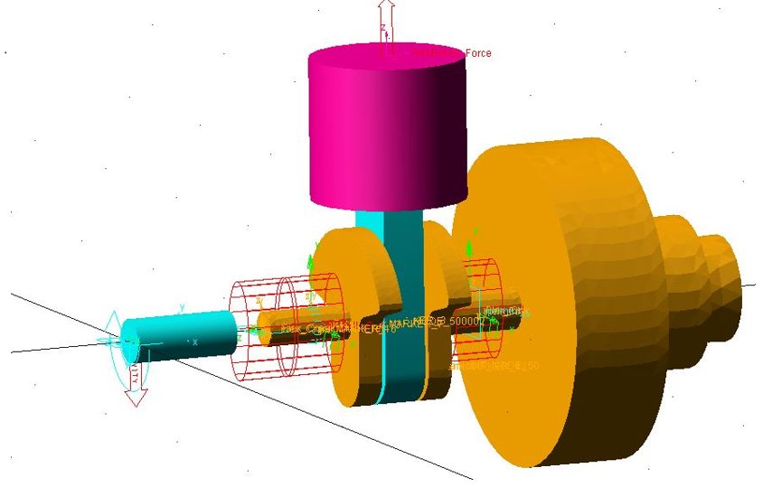
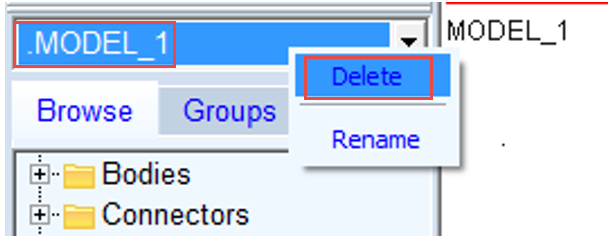
4. Delete Model_1 from database.
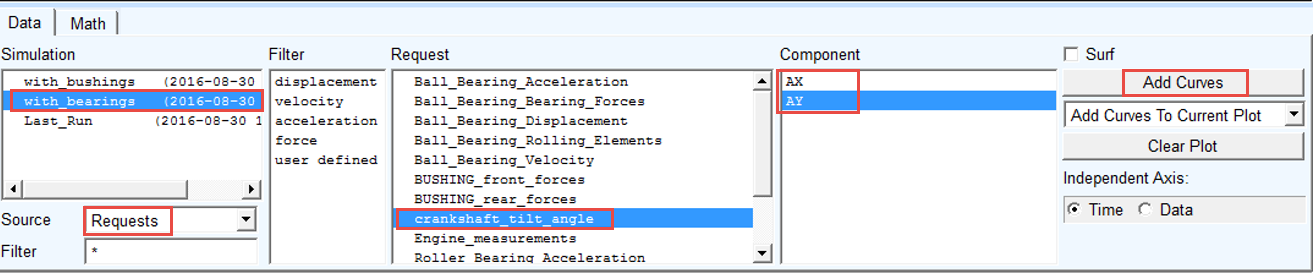
Create the Tilt Angle Request
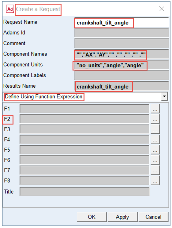
You have to create the request to measure the tilt angle between flexible crankshaft and ground in the location of the roller bearing.
To create the request:
1. Under the Design Exploration tab, select Create a new Request in the Instrumentation group.
.png)
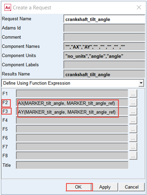
2. Enter the Request Name: crankshaft_tilt_angle.
3. Enter the Component Names: "","AX","AY","" ,"" ,"" ,"" ,"".
4. Enter the Component Units: "no_units","angle","angle".
5. Enter the Results Name: crankshaft_tilt_angle.
6. In the drop-down menu select “Define Using Function Expression”.
7. Push the ... button for the F2 function.
8. In the function builder for F2, select the Displacement function.
9. Select the Function: Angle about X.
10. Click Assist... button.
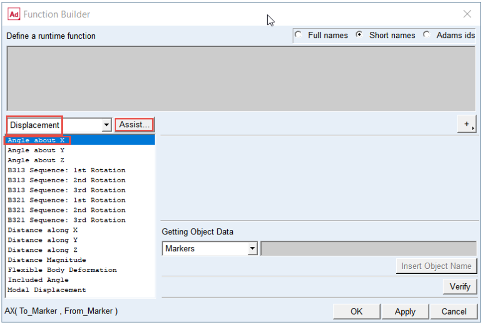
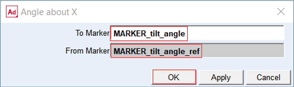
11. In the To Marker field, right-click and browse: MARKER_tilt_angle on Part: Flex_Crank.
12. In the From Marker field, right-click and browse: MARKER_tilt_angle_ref on Part: Ground.
13. Click the OK button on assist window.
14. Verify the syntax of the function definition.
15. Click the OK button on Function Builder window.
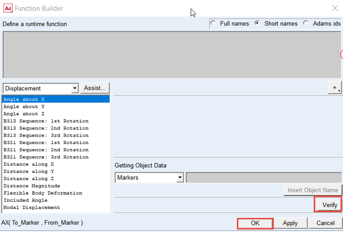
16. The function AX(MARKER_tilt_angle, MARKER_tilt_angle_ref) was imported in F2 field.
17. In the Field F3 create in a similar way the function AY(MARKER_tilt_angle, MARKER_tilt_angle_ref).
18. After you have created AX and AY functions the filled dialog box should look like the dialog box seen on the right side. Verify the inputs for Request and click the OK button on Create a Request dialog box.
Run a Dynamic Simulation and Save the Results
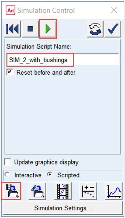
To run a simulation using the simulation script SIM_with_bushings:
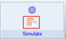
1. Under the Simulation tab, click Run a Scripted Simulation in the Simulate Group.
2. Select SIM_2_with_bushings as the Simulation Script Name.
3. Click Start Simulation.
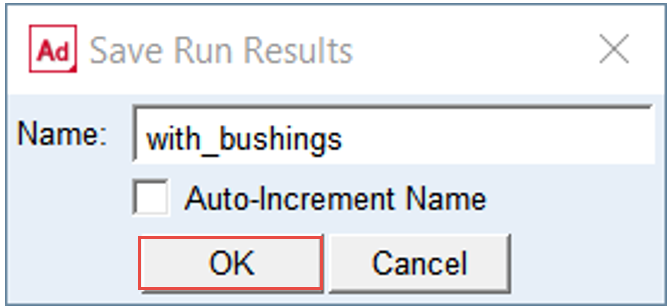
4. Save the Simulation Results as with_bushings.
5. Click the OK button.
Note: | The scale factor of the Flex_Crank deformation is set to 10.0, hence the deformation you will observe from animation of results will be exaggerated. |
Investigate simulation results
In the Adams Postprocessor investigate results of the crankshaft tilt angle:
1. Switch to Adams Postprocessor and press F8 on keyboard.
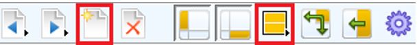
2. Create a new page.
3. Select Page Layout: 2 Views, over & under.
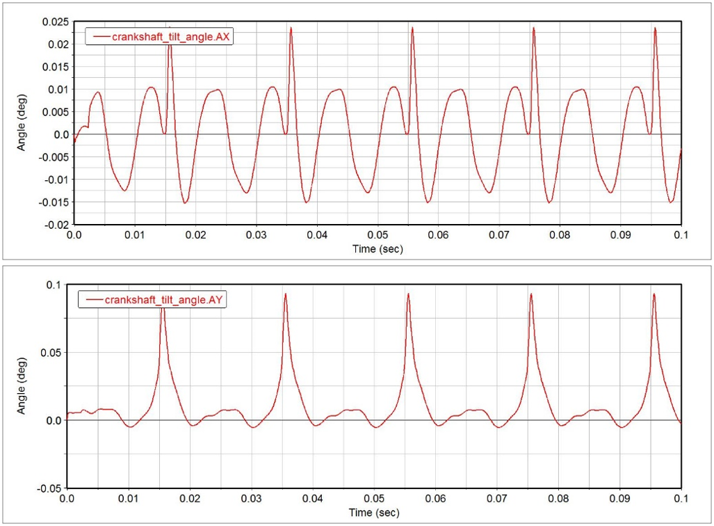
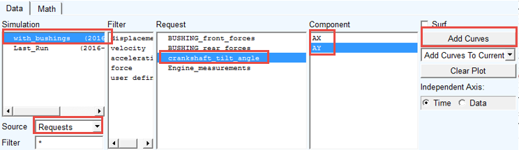
4. Left click in the upper plot and select the Simulation: with_bushings.
5. Select the Source: Requests.
6. Select the Request: crankshaft_tilt_angle.
7. Left click on the upper plot, select the Component: AX and click Add Curves button.
8. Left click on the lower plot, select the Component: AY and click Add Curves button.
Note: | Before you create the Bearing AT elements you have to follow these steps: 1. Preprocess Bearing Mesh. ■Enter bearing geometrical parameters. ■Execute meshing and Nastran analyses. 2. Preprocess Bearing Contact. ■Enter bearing contact parameters. ■Execute computation of compliances between ball elements and rings. |
In this workshop you can skip steps described above and use existing bearing property and contact files from the Bearing AT plugin installation. You have put the copy of the bearing files into working directory in the very first step of this workshop already.
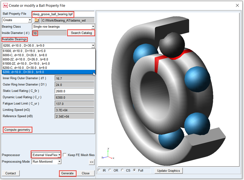
Preprocess FE Mesh of ball bearing
Creating FE Mesh of ball bearing:
1. In Bearing AT menu, select Ball Bearing → Preprocessing → Mesh.
.png)
2. Enter the name of ball property file: “deep_groove_ball_bearing”.
3. Enter required value “10” in the Inside Diameter (d) field and click on Search Catalog button.
4. In the option menu, select one of the Available Bearings (the values in the general tab are automatically filled in).
5. Click the Compute geometry button; required values in all tabs will be calculated.
6. Use External ViewFlex as preprocessor.
7. Investigate all parameters and display the roller bearing geometry by pushing the >> button.
8. Click the Generate button to execute Mesher and Nastran SOL 101.
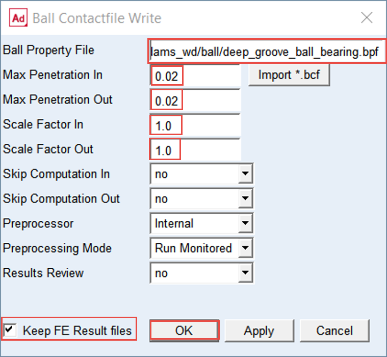
Preprocess FE Contact of ball bearing
Creating FE Contact of ball bearing:
1. In Bearing AT menu select Ball Bearing → Preprocessing → Contact.
.png)
2. From the directory: BearingAT_Workshop\bearings\ball select the ball bearing property file: deep_groove_ball_bearing.bpf
3. Set the value of Max Penetration In to 0.02
4. Set the value of Max Penetration Out to 0.02
5. Set the value of Scale Factor In to 1.0
6. Set the value of Scale Factor Out to 1.0
7. Check the toggle button on to Keep FE Results files, otherwise PCH files from Nastran execution will be removed from the disc.
8. Click the OK button.
Preprocess FE Mesh of roller bearing
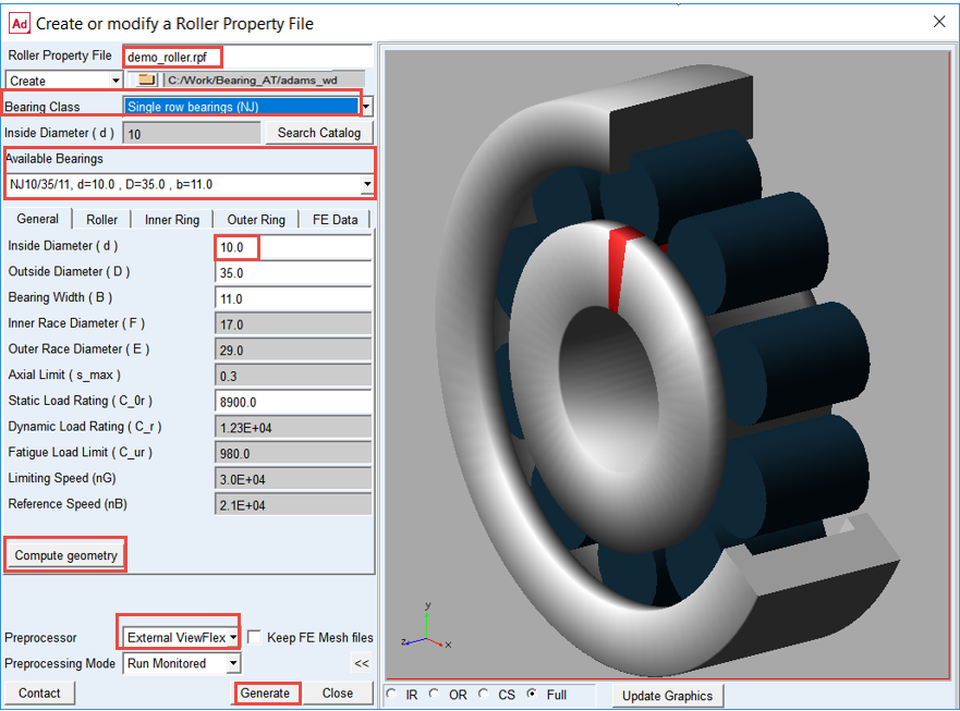
Creating FE Mesh of roller bearing:
1. In Bearing AT menu select Roller Bearing → Preprocessing → Mesh.
.png)
2. Enter the name of roller property file: “demo_roller”.
3. In the Bearing Class option menu select Single row bearings (NJ).
4. Enter required value “10” in the field of Inside Diameter (d) and click on Search Catalog button.
5. In the option menu, select one of the Available Bearings (the values in the general tab are automatically filled in).
6. Click on the Compute geometry button; all required values in all tabs will be calculated.
7. Use External ViewFlex as preprocessor.
8. Investigate all parameters and display the roller bearing geometry by pushing the >> button.
9. Click the Generate button to execute Mesher and Nastran SOL 101.
Preprocess FE Contact of roller bearing
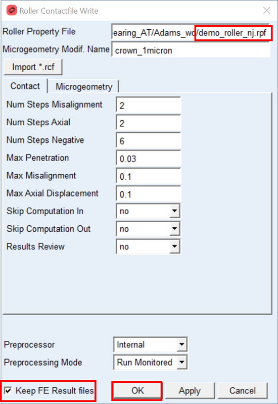
Creating FE Contact of roller bearing:
1. In the Bearing AT menu select the Roller Bearing → Preprocessing → Contact.
.png)
2. From the directory: BearingAT_Workshop\bearings\roller select the roller bearing property file: demo_roller.rpf
3. Fill in all values as shown on the Figure.
4. Check the toggle button on to Keep FE Results files, otherwise PCH files from Nastran execution will be removed from the disc.
5. Click the OK button.
Create the ball bearing using Bearing AT
To create the ball bearing element:
1. In the Bearing AT menu point to Ball Bearing → Element → New.
.png)
2. Enter the Bearing Name: Ball_Bearing.
3. Select the reference marker: MARKER_ball_bearing_ref on part: Flex_Crank.
4. Select the Shaft Part: Flex_Crank.
5. Select the Block Part: ground.
6. Browse the directory bearings/ball and select the ball bearing property file: deep_groove_ball_bearing.bpf
7. Enter the Total Radial Clearance: 0.01
8. Click the OK button.
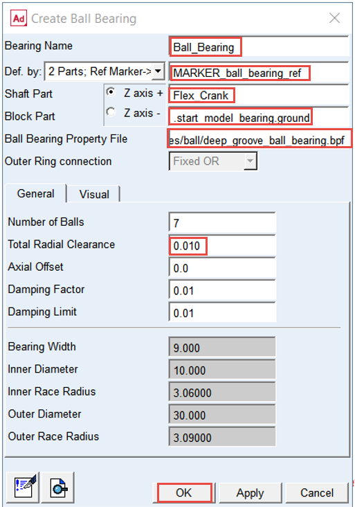
Note: | The value of Number of Balls and Total Radial Clearance parameters are populated from the *.bpf file, however you can enter different value of your choice without need of rerunning the preprocessing. Please note that these parameters values will be not written in the *.bpf file when you hit OK or Apply buttons but will be stored in Adams model (*.cmd) file or in Adams database file (*.bin). |
Create the roller bearing using Bearing AT
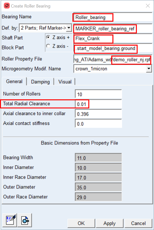
To create the roller bearing element:
1. In the Bearing AT menu point to Roller Bearing → Element → New.
.png)
2. Enter the Bearing Name: Roller_Bearing.
3. Select the reference marker: MARKER_roller_bearing_ref on part: Flex_Crank.
4. Select the Shaft Part: Flex_Crank.
5. Select the Block Part: ground.
6. Browse the directory bearings/roller and select the roller bearing property file: demo_roller.rpf
7. Enter the Total Radial Clearance: 0.01
8. Click the OK button.
Run a Dynamic Simulation and Save the Results
To run a simulation using the simulation script SIM_with_bearings (bushings are deactivated in the script):
1. Under the Simulation tab, click Run a Scripted Simulation in the Simulate Group.
2. Select SIM_3_with_bearings as the Simulation Script Name.
3. Click Start Simulation.
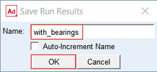
4. Save the Simulation Results as with_bearings.
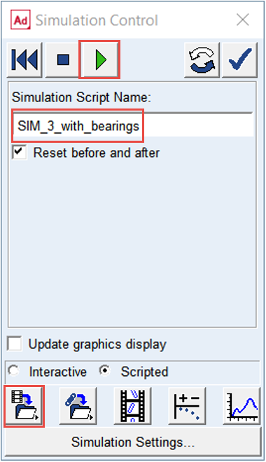
5. Click OK.
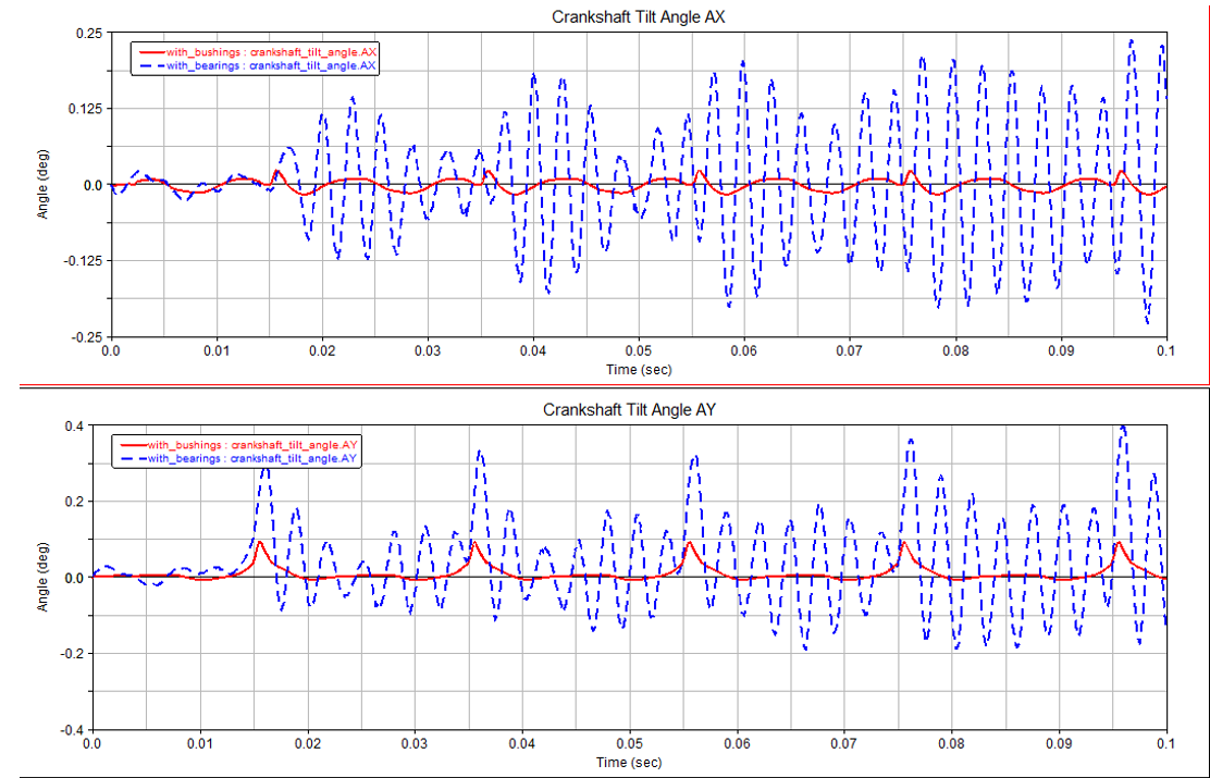
Investigate simulation results
In the Adams Postprocessor compare results of the crankshaft tilt angle of both simulations. Add curves to existing plots you made from simulation with_bushings:
1. Switch to Adams Postprocessor and press F8 on keyboard.
2. Select the Simulation: with_bearings.
3. Select the Source: Requests.
4. Select the Request: crankshaft_tilt_angle.
5. Left click on the upper plot, select the Component: AX and click Add Curves button.
6. Left click on the lower plot, select the Component: AY and click Add Curves button.
Investigate simulation results
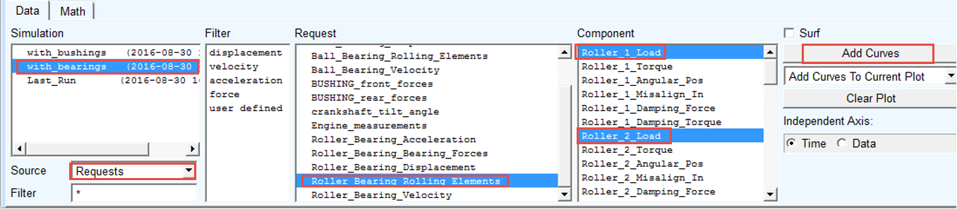
In Adams Postprocessor investigate results of loads of all rolling elements for both bearings from the last simulation:
1. Switch to Adams Postprocessor and press F8 on keyboard.
2. Create a new page.
3. Select Page Layout: 2 Views, over & under.
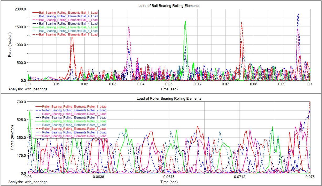
4. Left click in the upper plot select the Simulation: with_bearings.
5. Select the Source: Requests.
6. Select the Request: Ball_Bearing_Rolling_Elements.
7. Left click on the upper plot, select the Component: Ball_1_load and click Add Curves button. Repeat for all balls (up to Ball_7_load).
8. Select the Request: Roller_Bearing_Rolling_Elements.
9. Left click on the lower plot, select the Component: Roller_1_load and click Add Curves button. Repeat for all rollers (up to Roller_9_load).
Note: | Make note of maximum roller loads for setting up bearing animation later on. |
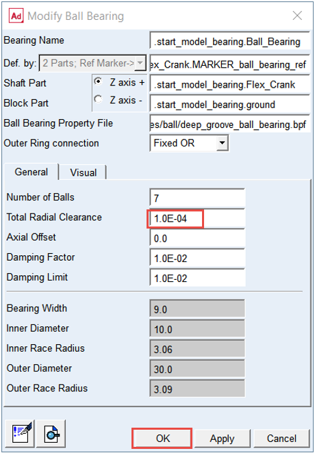
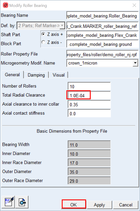
Modify the bearing radial clearance
You can see in the plots, that the crankshaft tilt angle from simulation with bearings is bigger then the tilt angle from simulation with bushings. Now, you will investigate the influence of radial clearance on the crankshaft tilt angle in the simulation with bearings.
To modify the radial clearance of bearings:
1. In the Bearing AT menu, select Ball_Bearing → Element → Modify.
.png)
2. Enter the Total Radial Clearance: 1.0E-4.
3. Click the OK button.
4. Similarly, navigate to Roller_Bearing menu and select Modify.
5. Enter the Total Radial Clearance: 1.0E-4.
6. Click the OK button.
Run a Dynamic Simulation and Save the Results
To run a simulation using the simulation script SIM_3_with_bearings:
1. Under the Simulation tab, click Run a Scripted Simulation in the Simulate Group.
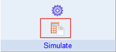
2. Select SIM_3_with_bearings as the Simulation Script Name.
3. Click Start Simulation.
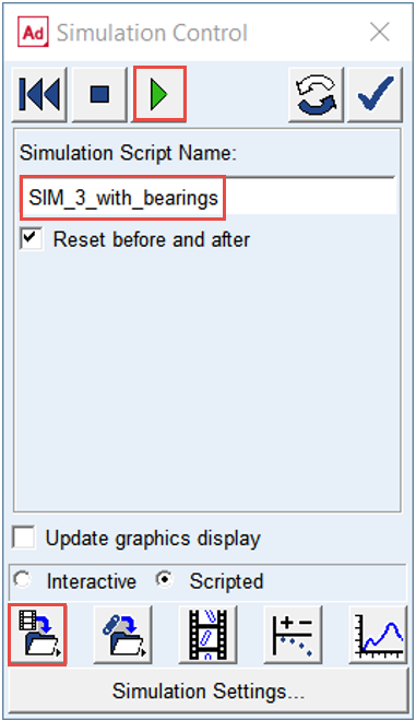
4. Save the Simulation Results as with_mod_bearings.
5. Click OK.
Animate Bearings Results
To animate bearings after simulation:
1. Under the Bearing AT menu, go to Animation Settings.
2. Select Animate all Bearings: yes.
3. Set the option Color one Ball Bearing to yes and Browse for Ball_Bearing.
4. Set the option Color one Roller Bearing to yes and Browse for Roller_Bearing.
5. Click OK.
.png)
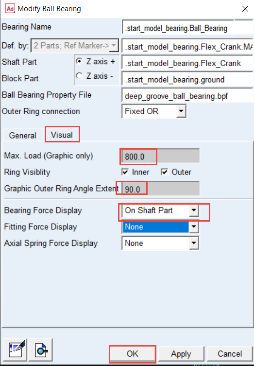
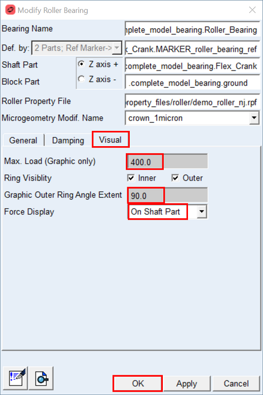
Modify bearing graphics
You can adjust bearing element graphics to better understand its loading condition. Use your notes you made in step 11.
To adjust graphics of bearings:
1. Point to the Ball_Bearing and select Modify.
2. Enter the Max. Load: 800.0.
3. Enter the Graphic Outer Ring Angle Extent: 90.0.
4. Select in the Force Display option menu: On Shaft Part.
5. Click the OK button.
6. Point to the Roller_Bearing and select Modify.
7. Enter the Max. Load: 400.0.
8. Enter the Graphic Outer Ring Angle Extent: 90.0.
9. Select in the Force Display option menu: On Shaft Part.
10. Click the OK button.
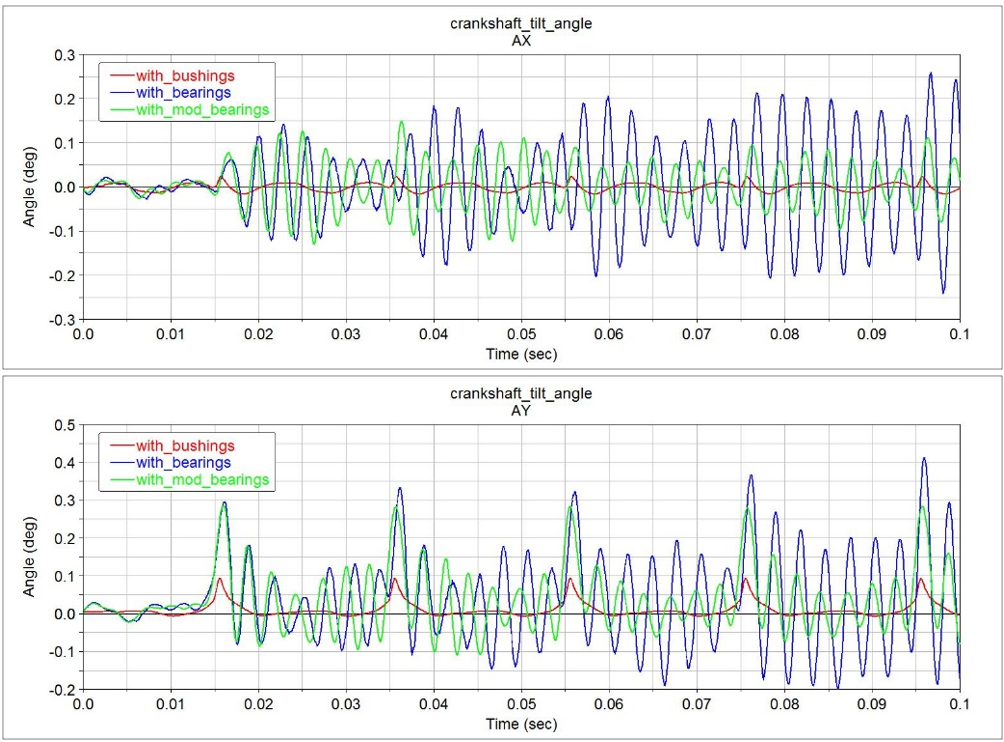
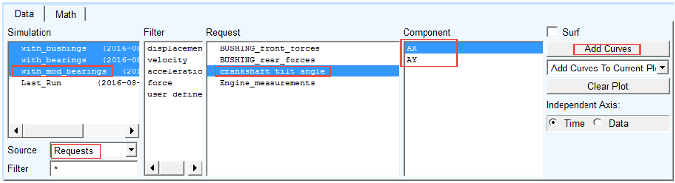
Investigate simulation results
Crankshaft tilt angle
In the Adams Postprocessor compare the crankshaft tilt angle of all three simulations. Add curves to existing plots you made from simulation with_bushings, with_bearings:
1. Switch to Adams Postprocessor press F8 on keyboard.
2. Select the Simulation: with_mod_bearings.
3. Select the Source: Requests.
4. Select the Request: crankshaft_tilt_angle.
5. Left click on the upper plot, select the Component: AX and click Add Curves button.
6. Left click on the lower plot, select the Component: AY and click Add Curves button.
Forces in rear bushing
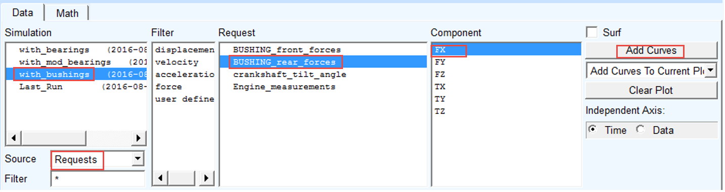
In the Adams Postprocessor compare the forces in rear bushing and rear roller bearing:
1. Create a new page
2. Select Page Layout: 2 Views, over & under.
3. Select the Simulation: with_bushings.
4. Select the Source: Requests.
5. Select the Request: BUSHING_rear_forces.
6. Left click in the upper plot, select the Component: FX and click Add Curves button.
7. Select the Simulation: with_bearings and with_mod_bearings.
8. Select the Request: Roller_Bearing_Bearing_Forces.
9. Select the Component: Radial_X and click Add Curves button.
In the Adams Postprocessor compare the forces in rear bushing and rear roller bearing:
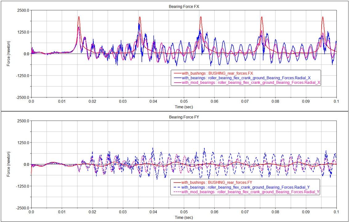
1. Left click in the lower plot
2. Select the Simulation: with_bushings.
3. Select the Source: Requests.
4. Select the Request: BUSHING_rear_forces.
5. Select the Component: FY and click Add Curves button.
6. Select the Simulation: with_bearings and with_mod_bearings.
7. Select the Request: Roller_Bearing_Bearing_Forces.
8. Select the Component: Radial_Y and click Add Curves button.
Investigate simulation results using Adams Durability
You can see that with smaller radial clearance the deflections of the flexible crankshaft is getting smaller. The stresses in the crankshaft with bearings with smaller radial clearance should decrease accordingly. You will compare the stresses in the crankshaft using Adams Durability plugin.
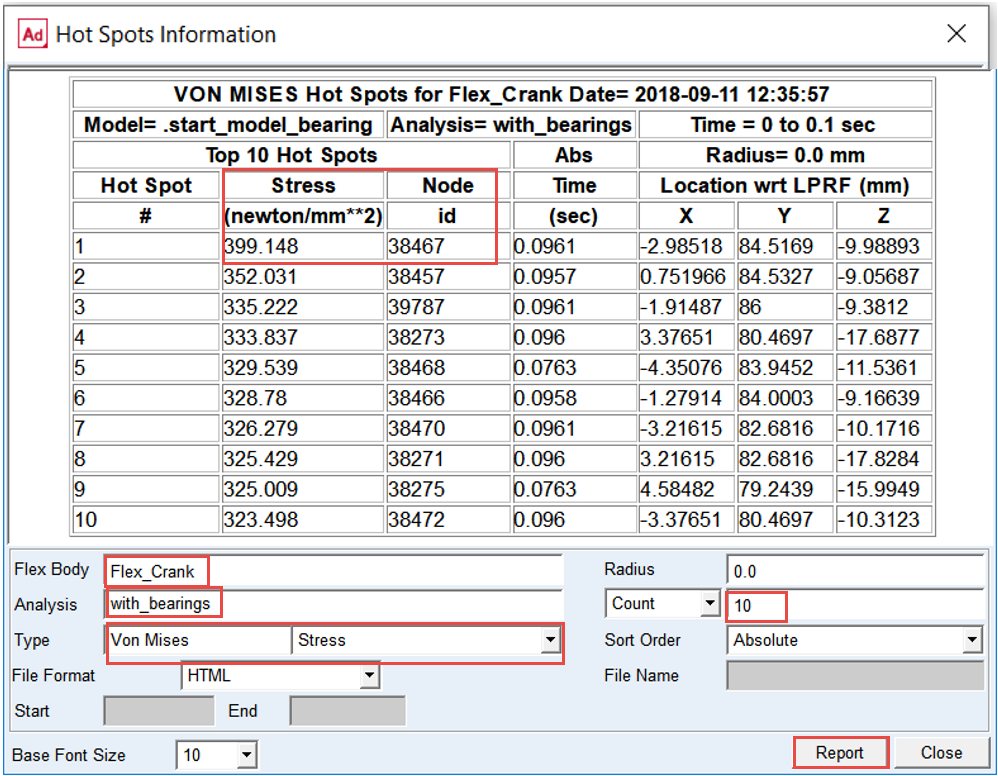
Stresses in flexible crankshaft with bearings
To recover stress of the flexible crankshaft in Adams you need to load Adams Durability plugin.
1. Click on the Plugins ribbon.
2. Left click in the Durability area to load Adams Durability menu.
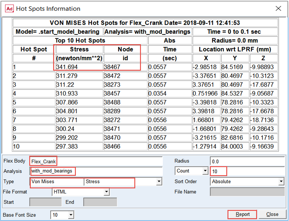
3. Select Hot Spots Table.
.png)
4. Select the flexible body: Flex_Crank.
5. Select the Analysis: with_bearings.
6. Select type of stress.
7. Select the number of hot spots: 10
8. Click Report.
9. Make a note of Node ID with the highest stress.
Stresses in flexible crankshaft with mod bearings
To recover stress of the flexible crankshaft in Adams you need to load Adams Durability plugin.
1. Click on the Plugins ribbon.
2. Left click in the Durability area to load Adams Durability menu.
3. Select Hot Spots Table.
4. Select the flexible body: Flex_Crank.
5. Select the analysis: with_mod_bearings.
6. Select type of stress
7. Select the number of hot spots: 10
8. Click Report.
9. Make a note of Node ID with the highest stress.
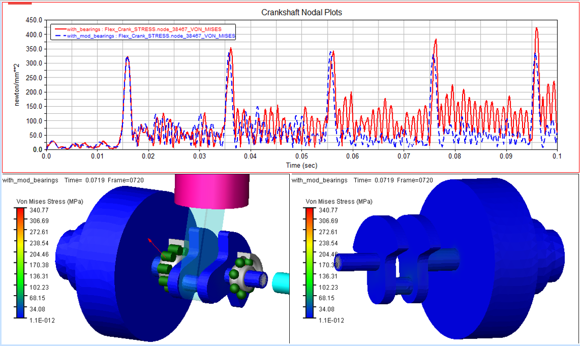
You can see that the stresses in the flexible crankshaft in the simulation with smaller radial clearance are significantly lower.
You will compare the time history of hot spot stresses of the crankshaft with modified bearing clearance using Adams Durability plugin.
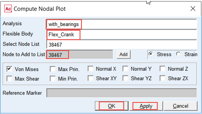
To compute nodal stress time history of the flexible crankshaft:
1. Click on the Plugins ribbon.
2. Left click in the Durability.
3. Select Nodal Plots.
.png)
4. Select the Analysis: with_bearings.
5. Select the flexible body: Flex_Crank.
6. Select type of stress.
7. Enter Node ID from the hotspot report in the Node to Add to list and Enter: 38467.
8. Press Apply.
9. Do the same for Analysis: with_mod_bearings.
10. Press OK.
To animate stress in Adams you need to load Adams Durability plugin and switch to Adams Postprocessor.
To load animations:
1. Switch to Adams Postprocessor and press F8 on keyboard.
2. Create a new page.
3. Select Page Layout: 3 Views.
4. Right click on lower left viewport, select Load animation and point to with_mod_bearings.
5. Select Contour Plots tab.
6. Select Von Mises Stress in the Contour Plot Type.
7. Repeat steps 4 to 6 for the lower right viewport.
8. Go to Animation tab right click in the Component field, go to Flexible_Body → Guesses → Flex_Crank.
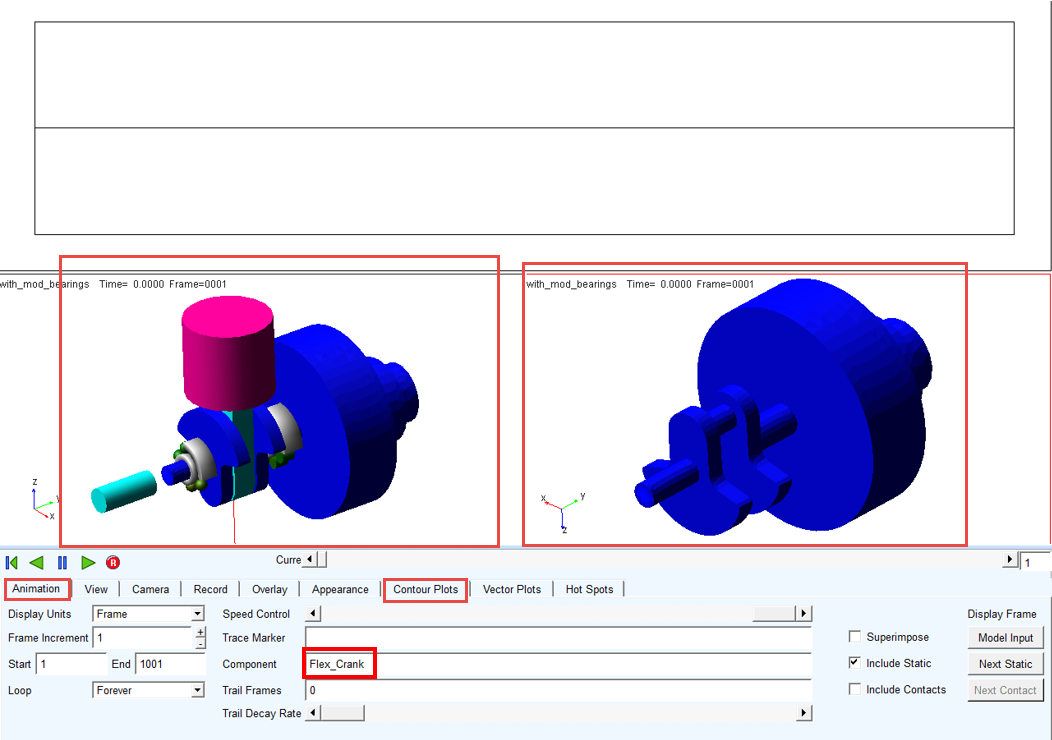
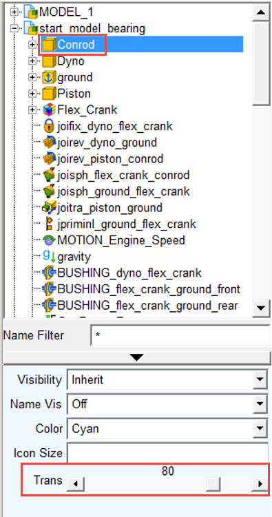
Change display attributes of conrod to better explore crankshaft stress.
To animate stresses:
9. Either left click on the conrod part in bottom left view port or select it from the model tree
10. Change transparency from 0 to 80 by dragging Trans slider.
Animate and plot nodal stresses of the flexible crankshaft.
To plot nodal stresses:
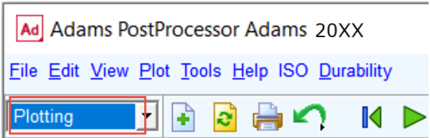
11. Left click on the upper view port and make sure it is in Plotting mode.
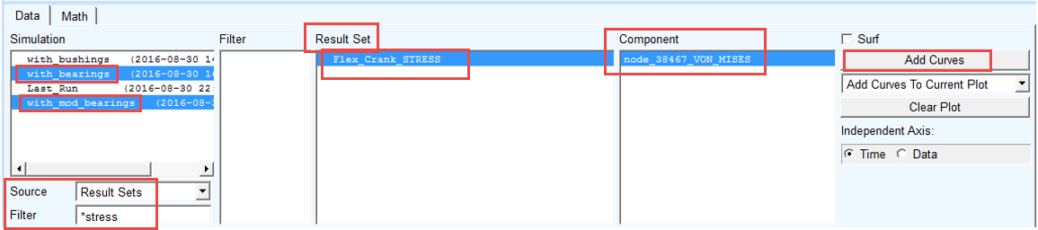
12. Select the Simulation: with_bearings, with_mod_bearings.
13. Select the Source: Result Sets.
14. Enter in the Filter: *stress and hit Enter key
15. Select the Result Sets: Flex_Crank_Stress.
16. Select the Component: node_38467_VON_MISES; click Add Curves button.
17. Play Animation.