Creating Axial Cylindrical Roller Bearing
What You Will Create
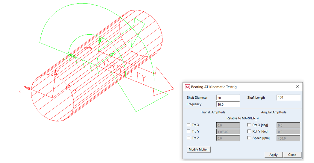
The model represents bearing element mounted on kinematic testrig consisting of rigid crankshaft and motion. You will create an axial cylindrical roller bearing, exercise it on the testrig and investigate results from kinematic simulation.
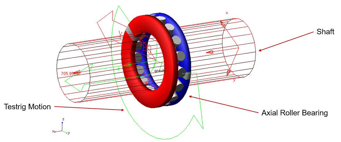
Figure 1 Testrig Model with Bearing AT Element
Prepare your working directory
To prepare your working directory:
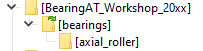
1. Navigate to your working directory (in this document it is BearingAT_Workshop_20XX), in which you create new directory named as bearings and sub-directory axial_roller to store all files related to bearings.
Start Adams View
To load a Bearing AT plugin:
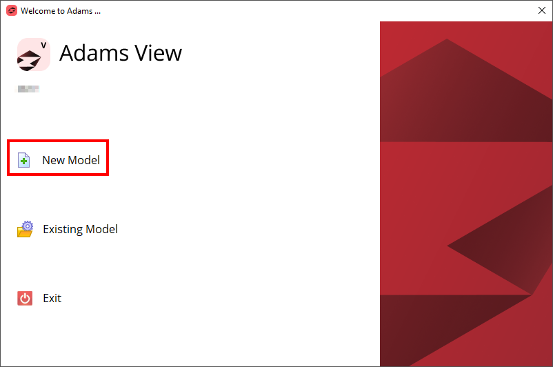
1. Under the Welcome dialog box, select New Model.
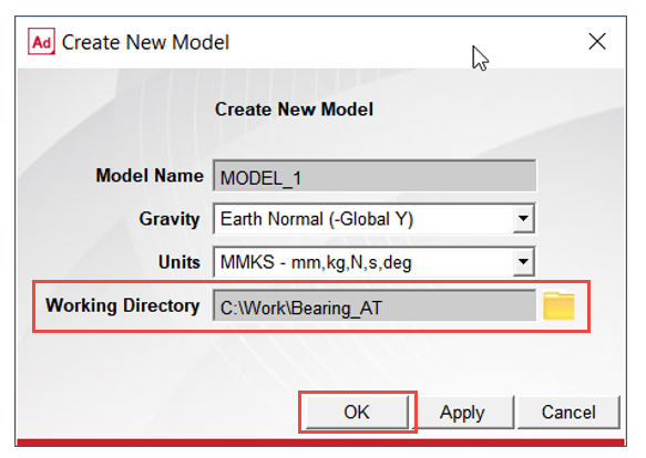
2. Set the Working Directory as BearingAT_Workshop_20XX.
3. Click the OK button.
.
Load the Bearing AT Testrig Model
To load the workshop model:
1. Click the Machinery tab on the Adams View ribbon and from the Bearing container, click the icon to pop up Bearing AT menu.
2. In the Bearing AT menu, select Test Model → Testrig → Kinematic Testrig.
.png)
3. The Testrig model was loaded.
Preprocess FE Mesh of axial cylindrical roller bearing
Creating FE Mesh of axial cylindrical roller bearing:
1. In Bearing AT menu, select Axial Roller Bearing → Preprocessing → Mesh.
.png)
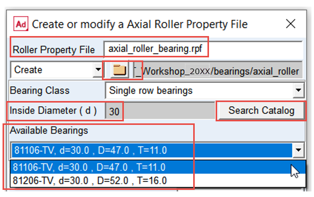
2. Enter the name of bearing property file: “axial_roller_bearing”
3. Select destination folder for property files by browsing to the “bearings/axial_roller” directory.
4. Enter required value of bearing Inside Diameter (d): 30.
5. Click the Search Catalog button.
6. In available bearings menu you can find number of bearings with the same inside diameter and different outside diameter and height. In this workshop we will use bearing: 81106-TV.
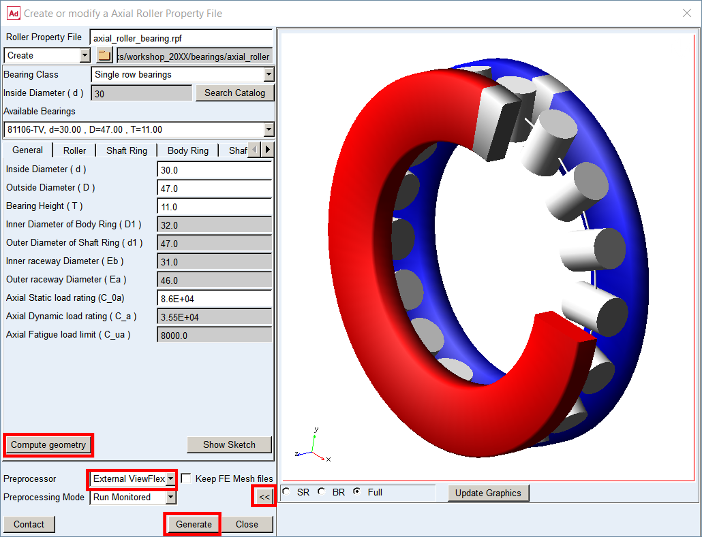
7. Click the Compute geometry button to compute bearing macro-geometry; all fields in all tabs in this dialog box are filled up with values.
8. Investigate all parameters and display the axial roller bearing geometry by clicking the >> button.
9. Use External ViewFlex as preprocessor.
10. Click the Generate button to execute Mesher and Nastran SOL 101.
Preprocess FE Contact of axial cylindrical roller bearing
Creating FE Contact of axial cylindrical roller bearing:
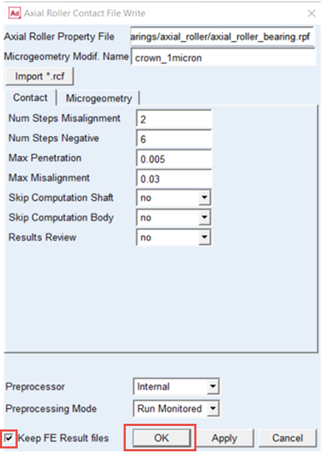
1. In Bearing AT menu, select Axial Roller Bearing → Preprocessing → Contact.
.png)
2. From the directory: BearingAT_Workshop_20XX\bearings\axial_roller select the axial roller bearing property file: axial_roller_bearing.rpf.
3. Enter values in fields as shown in figures.
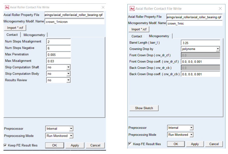
4. Check the toggle button on to Keep FE Results files, otherwise PCH files from Nastran execution will be removed from the disk space.
5. Click the OK button.
Creating axial cylindrical roller bearing element
To create the axial roller bearing element:
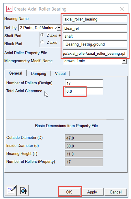
1. In the Bearing AT menu, select Axial Roller Bearing → Element → New.
.png)
2. Enter the Bearing Name: axial_roller_bearing.
3. Select the reference marker: Bear_ref on part: Ground.
4. Select the Shaft Part: Shaft.
5. Select the Block Part: ground.
6. Browse the directory bearings/axial_roller and select the axial roller bearing property file: axial_roller_bearing.rpf.
7. Enter the Total Axial Clearance: 0.0
8. Click the OK button.
Running a Kinematic Simulation and Saving the Results
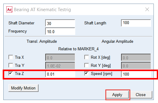
Before running a kinematic simulation set up kinematic testrig parameters:
.png)
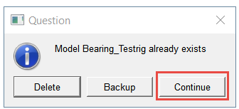
1. In case you closed the dialog box of kinematic testrig open it up by loading it from the Bearing AT menu; click on Continue button.
2. Set the axial amplitude for translation Tra Z to 0.01 and rotation Speed [rpm] to 100.
3. Click Apply.
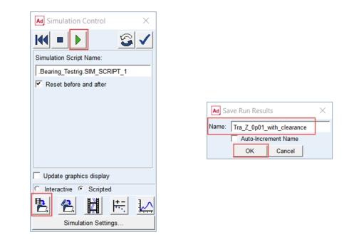
To run a kinematic simulation using the simulation script SIM_SCRIPT_1:
4. Under the Simulation tab, click Run a Scripted Simulation in the Simulate Group.
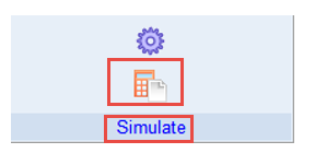
5. Select SIM_SCRIPT_1 as the Simulation Script Name.
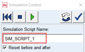
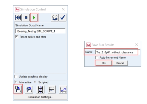
6. Click Start Simulation.
7. Save the Simulation Results as Tra_Z_0p01_without_clearance.
8. Click the OK button.
Modify axial clearance of the bearing
To modify the axial clearance of bearing:
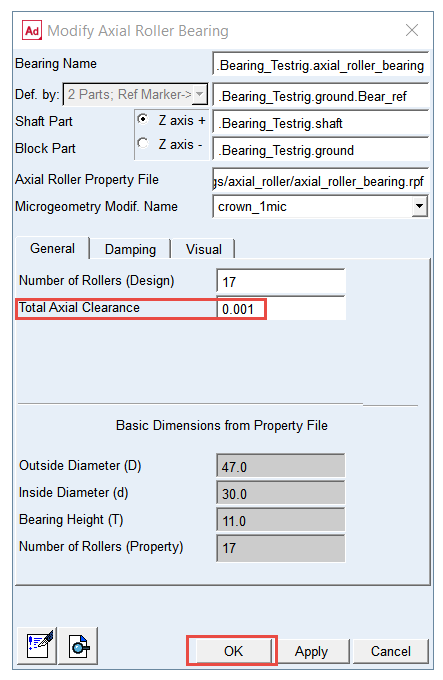
1. In the Bearing AT menu, select Axial Roller Bearing → Element → Modify.
.png)
2. Enter the Total Axial Clearance: 1.0E-3.
3. Click the OK button.
Run a Kinematic Simulation and Save the Results
To run a kinematic simulation using the simulation script SIM_SCRIPT_1:
1. Under the Simulation tab, click Run a Scripted Simulation in the Simulate Group.
2. Select SIM_SCRIPT_1 as the Simulation Script Name.
3. Click Start Simulation.
4. Save the Simulation Results as Tra_0p01_with_clearance.
5. Click the OK button.
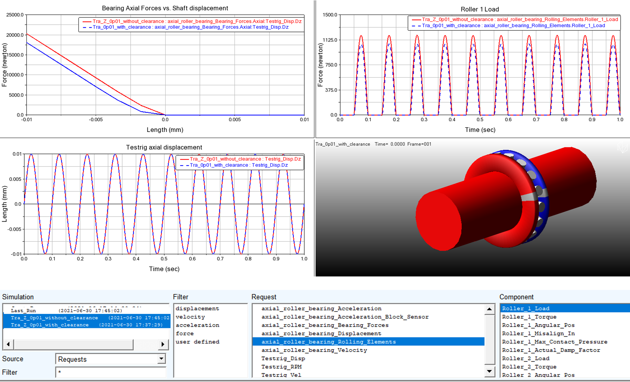
Investigating simulation results
In the Adams Postprocessor compare bearing axial force and roller load. Cross plot curves from two simulations you have run, that is, Tra_Z_ 0p01 _without_clearance and Tra_Z_ 0p01 _with_clearance:
1. Switch to Adams Postprocessor and press F8 on keyboard.
2. Select the Source: Requests.
3. Left click on the lower left plot, select request Testrig_Disp and select the component Dz and click on Add Curves button.
4. Left click on the upper right plot, select the request Rolling_Elements and select component Roller_1 Load and click on Add Curves button.
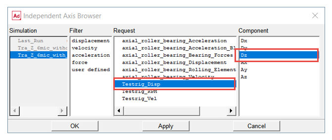
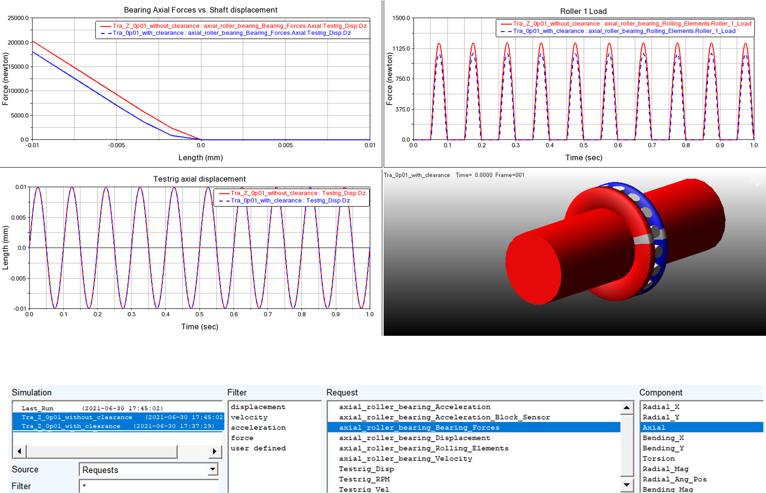
5. Switch to Data for Independent Axis and select request Testrig Disp and component Dz.
6. Left click on the upper left plot, select request Bearing_Forces and select component Axial and click on Add Curves button.
Saving your Work
You can save your work for future reference. To save your model:
1. Switch to Adams View and press F8 on keyboard.
2. In the File menu select Export...
3. Select the File Type: Adams View Command File.
4. Enter File Name as WS_01_finished.
5. Click the OK button.
6. The CMD file is exported to your working directory.