Creating a Bevel/Hypoid Gear Pair
During this tutorial, you will define a bevel gear tooth profile by processing of CAD geometry. To extract tooth profile from CAD geometry you need to enter essential dimensions of the gear in the shape definition step of Gear AT preprocessing. After Shape definition processing is finished all relevant geometrical data including profile are stored in a hypoid gear property file, which is used as input for meshing and for bevel/hypoid gear element definition.
Next step is to generate FE meshes, then run Nastran SOL 101 and extract stiffness matrix to a hypoid gear stiffness file, which is then used for gear force definition. And finally, execute a simulation and investigate the results.
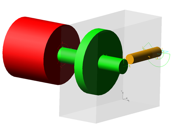
Figure 1 shows a bevel gear pair that you are going to create.
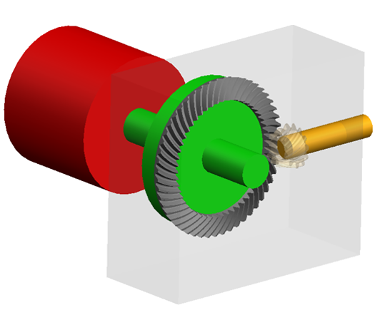
Figure 1 Bevel Gear Pair
Prepare your Working Directory
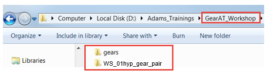
1. Navigate to your working directory in which you create new directory named gears to store all files related to gears.
2. Copy files: Bevel_WS01.hgd, Pinion.x_t, Wheel.x_t from Adams_Install_dir\gear_at\examples\hypoid to gears directory
3. Go back to your working directory and create new directory named WS_01hyp_gear_pair
4. Start Adams either from desktop or Windows Start menu → All Programs → Adams 202x.x.
Start Adams View
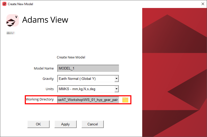
1. Under the Welcome dialog box, select New Model.
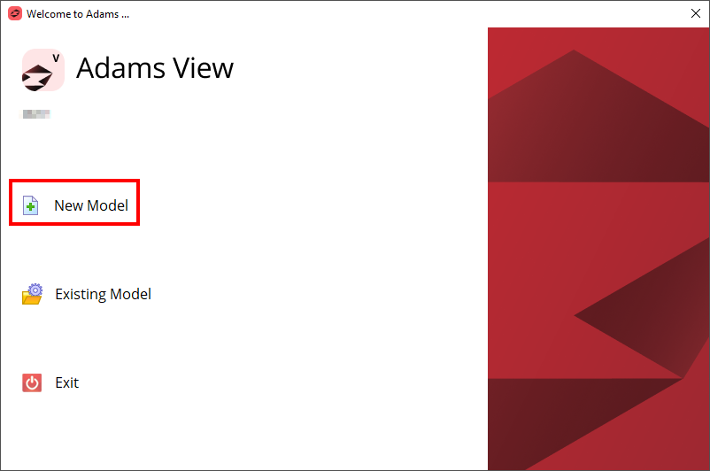
2. Set the Working Directory to WS_01hyp_gear_pair.
3. Click the OK button.
Load the Workshop Model
To load a Workshop Start Model:
1. Click the Machinery tab on the Adams View ribbon and from the Gear AT container, click the icon to pop up Gear AT menu
2. In the Gear AT menu → Help → Getting started → Bevel gears → Workshop Start Model.
.png)
3. The starting workshop model gear_at_hyp_model was loaded.
Creating Pinion Tooth Property File
At this point there are no gear property files (*.hgp) available, so we have to prepare them from scratch. In this step we extract bevel gear tooth profile by processing of CAD geometry (*.x_t parasolid file). All input dimensions of both the gears are stored in so called definition file (*.hgd file).
To Extract Pinion Tooth Profile:
1. In the Gear AT menu, select Bevel/Hypoid Gear → Gear AT Preprocess → Gear AT Shape Definition Hypoid.
.png)
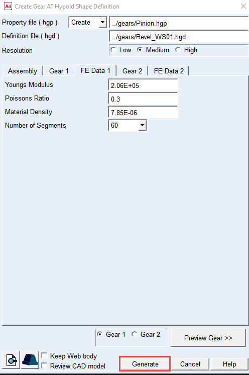
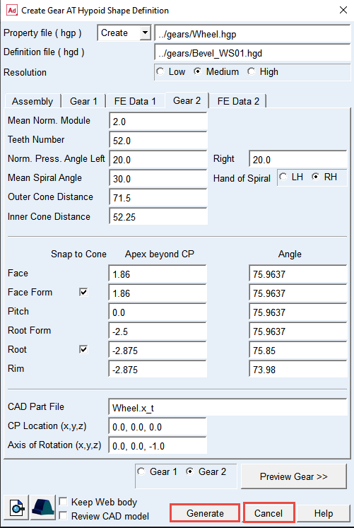
2. In the Definition file (hgd) field right Click and Browse to the ../gears directory and select Bevel_WS01.hgd (name of Property file will be filled in automatically if the field is empty, otherwise edit manually).
3. Set the Resolution radio button to Medium, to control number of profile points extracted from a section through CAD geometry.
4. Set the gear radio button to Gear 1.
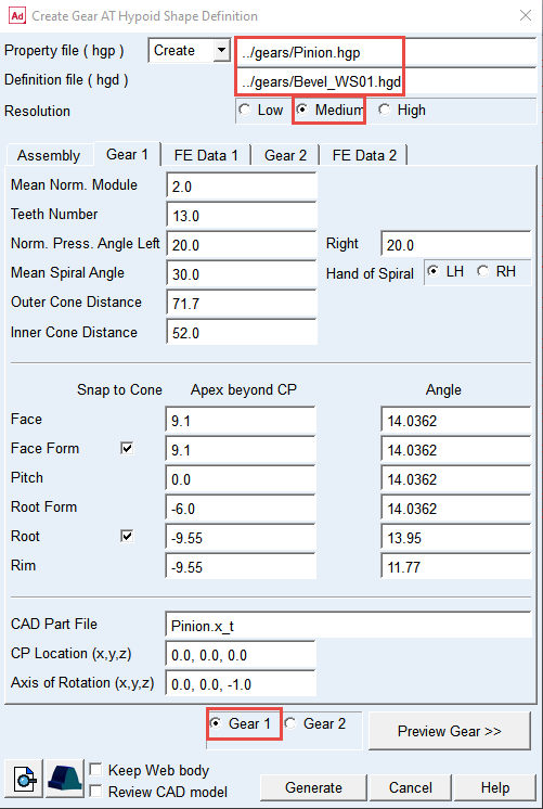
5. In the FE Data 1 tab set the Number of Segments to 60.
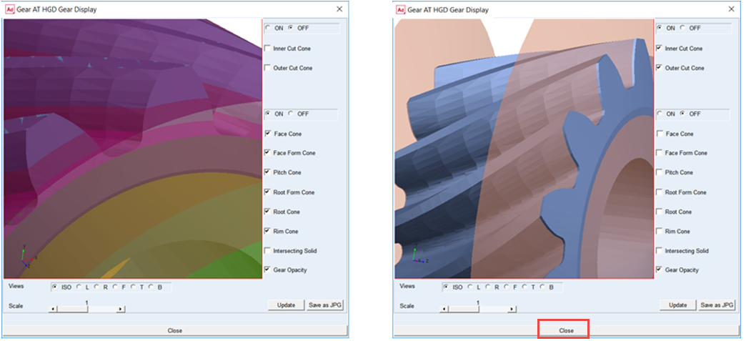
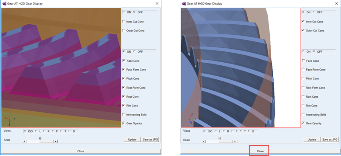
6. Click the Preview Gear >> button to see how cutting cones match the CAD geometry.
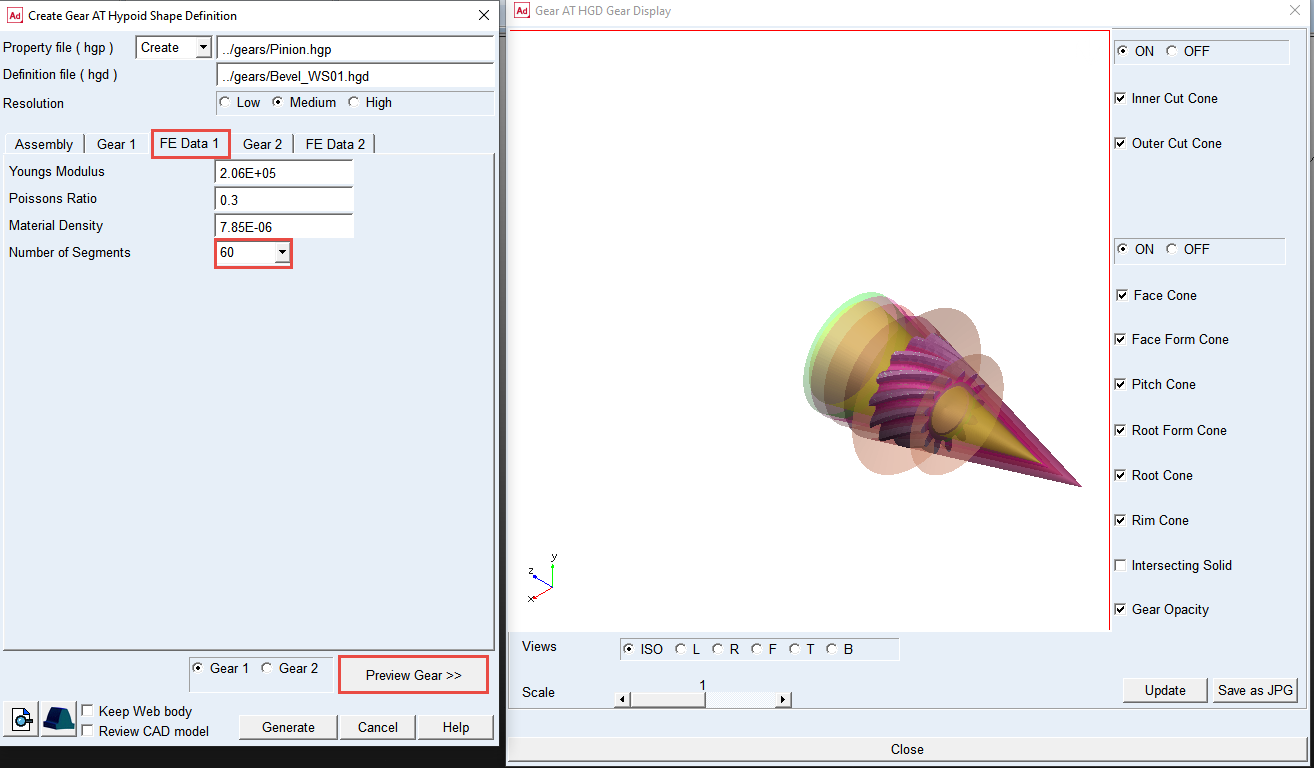
7. Check the displayed cutting cone surfaces of the gear and adjust the values in fields of the Shape Definition dialog box if necessary to make proper tooth extraction and close this preview window when ready by clicking on Close button.
8. Click the Generate button in Shape Definition dialog box window and wait for CAD import to complete.
9. The pinion.hgp file is created in the ../gears directory.
Creating Wheel Tooth Property File
The hypoid definition file (*.hgd) comprises the data of both gears of a gear pair. In previous step we prepared hypoid gear property (*.hgp) file of the gear 1, now we prepare a property file of the gear 2.
To Extract Wheel Tooth Profile:
1. In the Definition file field, right click and Browse to the ../gears directory and select Bevel_WS01.hgd (make sure the Definition file field points to the same file as for the 1st gear).
2. Set the Resolution radio button to Medium.
3. Set the gear radio button to Gear 2 (name of Property file will be filled in automatically if the field is empty, otherwise edit manually).
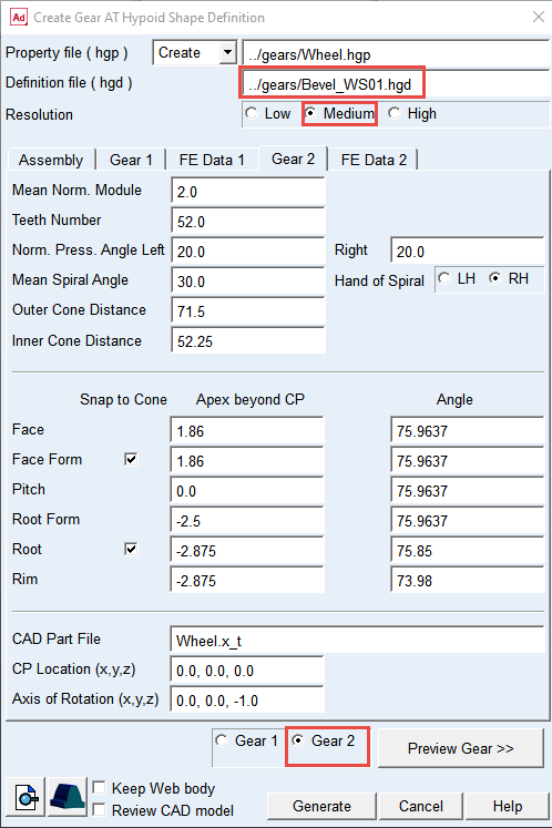
4. In the FE Data 2 tab set the Number of Segments to 60.
5. Click the Preview Gear >> button to see how cutting cones match the CAD geometry.
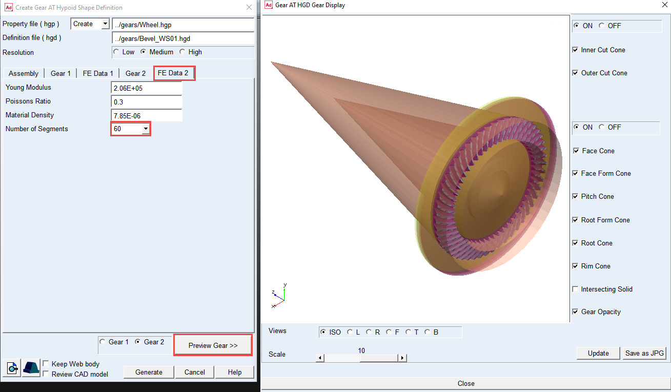
6. Check the displayed cutting cone surfaces of the gear and adjust the values in fields of the Shape Definition dialog box if necessary to make proper tooth extraction and close this preview window when ready by clicking on Close button.
7. Click the Generate button in Shape Definition dialog box window and wait for CAD import to complete.
8. The Wheel.hgp file is created in the ../gears directory. Close the Gear AT Shape Definition dialog box by pushing the Cancel.
Meshing Pinion Tooth
In this step we preprocess FE mesh of a flexible tooth based on profiles stored in a property (*.hgp) file and generate shell file for Adams geometrical representation. Hereafter the stiffness matrix of a flexible tooth is generated with the help of Nastran embedded solver in Adams which is stored in *.hgs file located in the gears folder. It will be referenced for the gear pair force definition later on.
To Create Nastran Mesh and Geometry of the Pinion:
1. In the Gear AT menu, select Bevel/Hypoid Gear → Gear AT Preprocess → Gear AT Mesh.
.png)
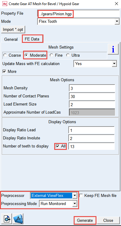
2. Right Click and Browse the ../gears directory for the Property File: pinion.hgp.
3. Select the FE Data tab.
4. Select the Mesh Setting to Moderate.
5. Select the More toggle for more options.
6. In the Display Options, select All for the Number of teeth to display toggle.
7. Select the Preprocessor: External ViewFlex.
8. Select the Preprocessing Mode: Run Monitored.
9. Click the Generate button, and select Yes to confirm the start of preprocessing and wait till the SOL101 is completed.
Meshing Wheel Tooth
To Create Nastran Mesh and Geometry of the Wheel:
1. In the Gear AT menu, select Bevel/Hypoid Gear → Gear AT Preprocess → Gear AT Mesh.
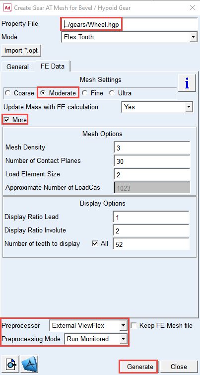
2. Right Click and Browse the ../gears directory for the Property File: wheel.hgp.
3. Select the FE Data tab.
4. Select the Mesh Setting to Moderate.
5. Select the More toggle for more options.
6. In the Display Options, select All for the Number of teeth to display toggle.
7. Select the Preprocessor: External ViewFlex.
8. Select the Preprocessing Mode: Run Monitored.
9. Click the Generate button, and select Yes to confirm the start of preprocessing and wait till the SOL101 is completed.
Creating Pinion Gear AT Element
To create the Pinion Gear AT Element:
1. In the Gear AT menu, select Bevel/Hypoid Gear → Gear AT Element → New.
.png)
2. Enter the Gear Name: Pinion.
3. Right click and Browse the ../gears directory for the Property File name: pinion.hgp.
4. Right click in the Ring Gear Reference Marker field and navigate to Marker → Browse.
5. In the Database Navigator, select Pinion_ref under the Pinion_Shaft part.
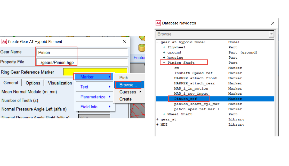
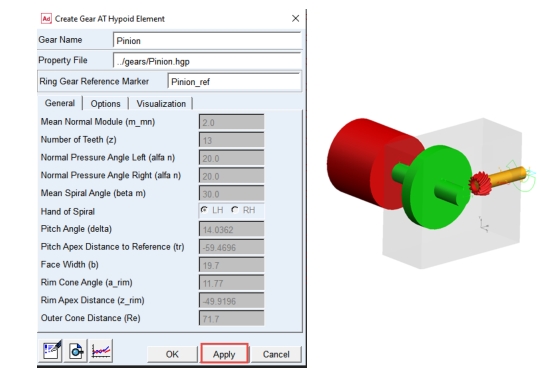
6. Click the Apply button.
7. The Pinion Gear AT Element has been created.
Creating Wheel Gear AT Element
To create the Wheel Gear AT Element:
1. In the Gear AT menu, select Bevel/Hypoid Gear → Gear AT Element → New.
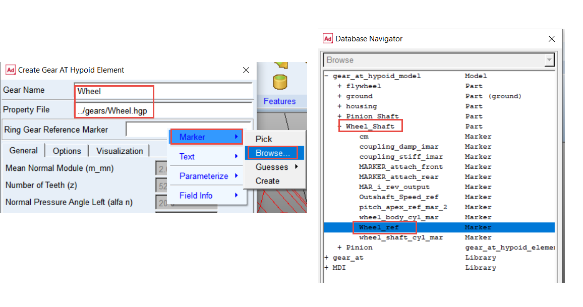
2. Enter the Gear Name: Wheel
3. Right click and Browse the ../gears directory for the Property File name: Wheel.hgp.
4. Right click in the Ring Gear Reference Marker field and navigate to Marker → Browse.
5. In the Database Navigator, select Wheel_ref under the Wheel_Shaft part.
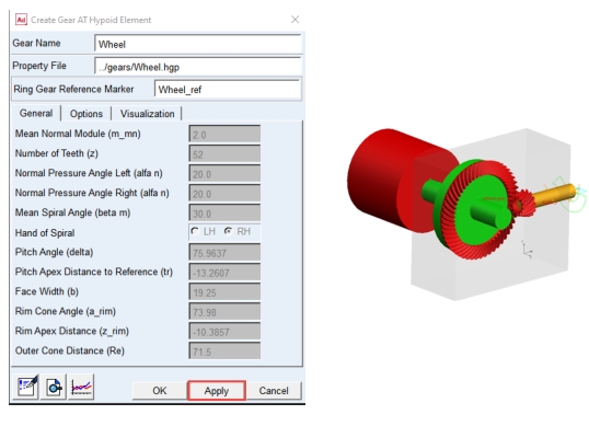
6. Click the OK button.
7. The Wheel Gear AT Element has been created.
Creating Gear AT Force for hypoid gear pair
Before creating Gear AT Force for hypoid Gear Pair we have to modify the design variables to adjust axial position of both gears with respect to crossing point.
To adjust axial position of the Pinion and Wheel element
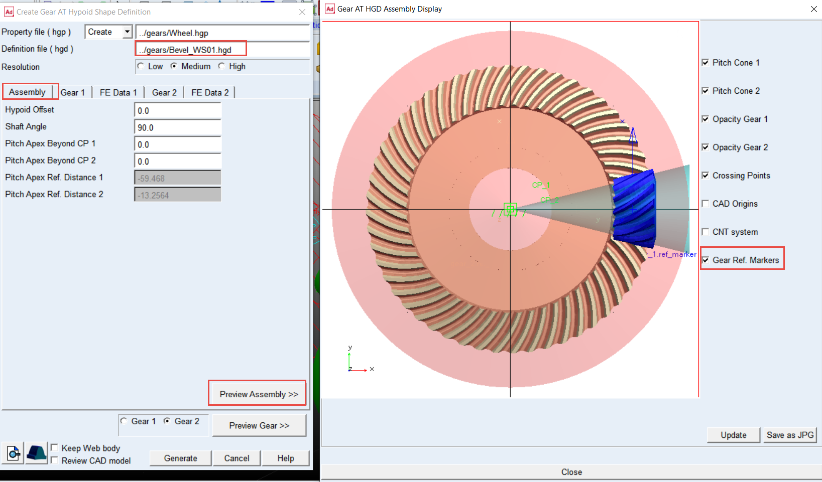
1. In the Gear AT menu, select Bevel/Hypoid Gear → Gear AT Preprocess → Gear AT Shape Definition Hypoid.
2. In the Definition file (hgd) field, right click and Browse for ../gears Bevel_WS01.hgd.
3. In Assembly tab, click Preview Assembly >> button and check on the Gear Ref. Markers toggle.
4. Make notes of Pitch Apex Ref. Distance 1 and Pitch Apex Ref. Distance 2 to edit design variables pitch_apex_ref_dist_1 and pitch_apex_ref_dist_2 in the model.
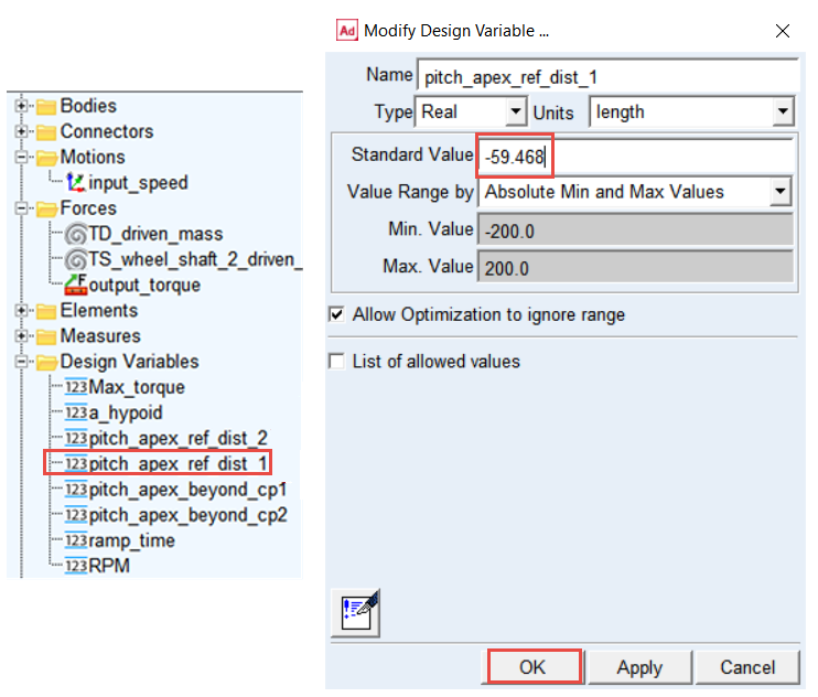
5. In the model browser, under the Design Variables, double click the pitch_apex_ref_dist_1 design variable (for Pinion).
6. To set proper mounting location of the Pinion, enter in the Standard Value field: -59.468; click OK. button. To increase the backlash one has to apply higher absolute value than found in the Assembly tab.
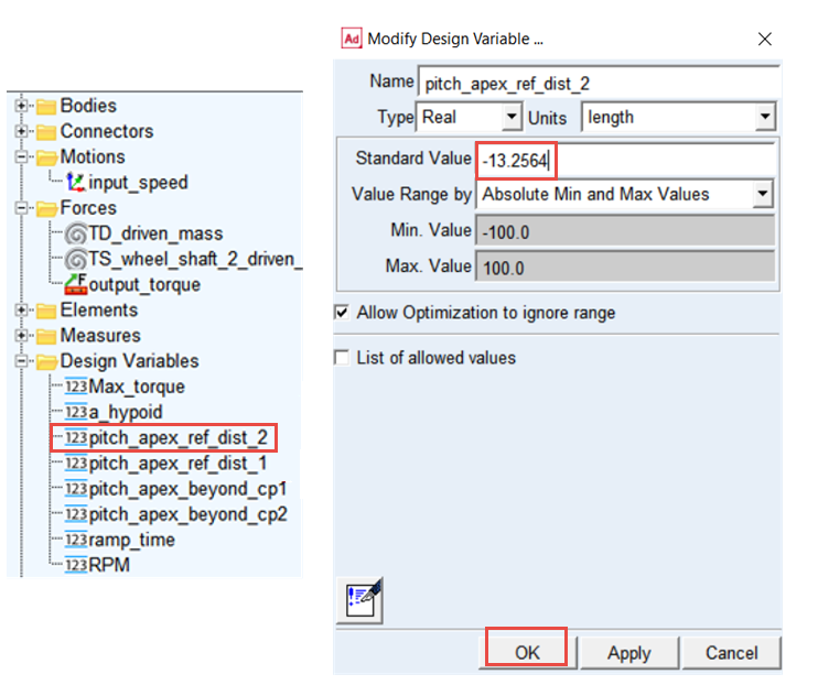
7. In the model browser double click the pitch_apex_ref_dist_2 design variable (for Wheel).
8. To set proper mounting location of the Wheel enter in the Standard Value field: -13.2564; click OK button.
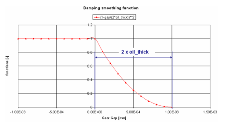
Theory – Damping Force
The function b is defined by:
 | (1) |
is used to smooth the damping.
There is no hydrodynamic damping, when b < 0:
 | (2) |
Hydrodynamic damping increases exponentially with decreasing oil film height. The introduction of the damping exponent d_exp:
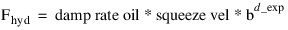 | (3) |
is used for this purpose. See Figure 2
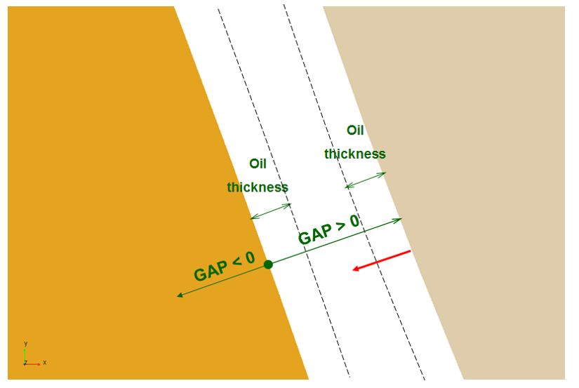
Figure 2 Oil Film Thickness
The structural damping force is made proportional to the contact force as shown by:

A value of 0.01 means, that the structural damping force is 1.0 percent of the elastic contact force.
Theory – Friction Force
The static friction coefficient  is usually somewhat higher than the dynamic friction
  coefficient. Step functions are used for smoothing the transitions. See Figure 3. Parameter of slip velocity (Vs) limits the region of sign change of the sliding velocity.
is usually somewhat higher than the dynamic friction coefficient. Step functions are used for smoothing the transitions. See Figure 3. Parameter of slip velocity (Vs) limits the region of sign change of the sliding velocity.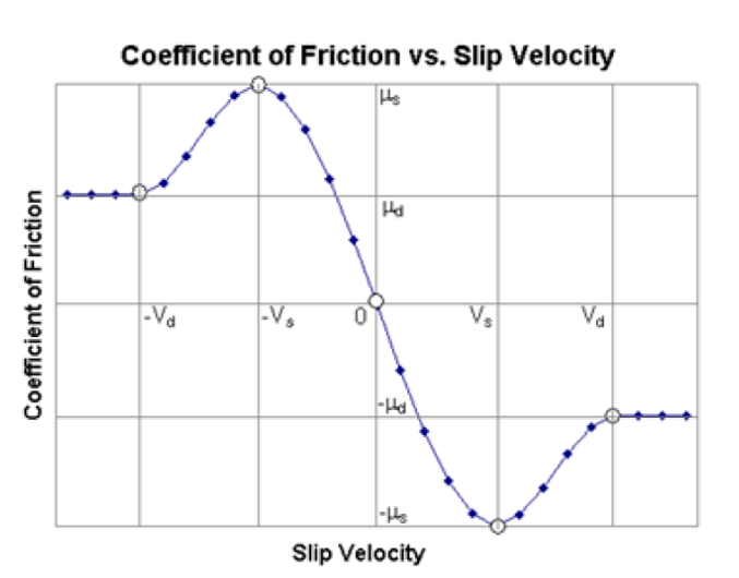
Figure 3 Coefficient of Friction vs, Slip Velocity
The combination of very small slip velocity (Vs) and high friction can reduce the performance of the integrator. You are advised to validate this selection through postprocessing of the sliding velocity.
Transition velocity (Vd) defines the start of the region, where the dynamic friction is constant. A small difference between slip velocity (Vs) and transition velocity (Vd) could also lead to numerical issues of the integrator.
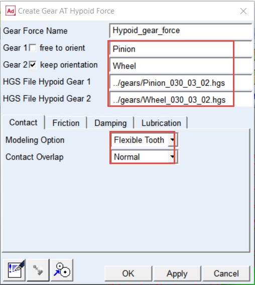
Create the Gear AT Force for the gear pair
1. In the Gear AT menu, select Bevel/Hypoid Gear → Gear AT Force → New.
.png)
2. Enter the Gear Force Name: Hypoid_gear_force.
3. Right click the Gear 1 field and select gear_at_hypoid_element → Browse.
4. In the Database Navigator, select Pinion
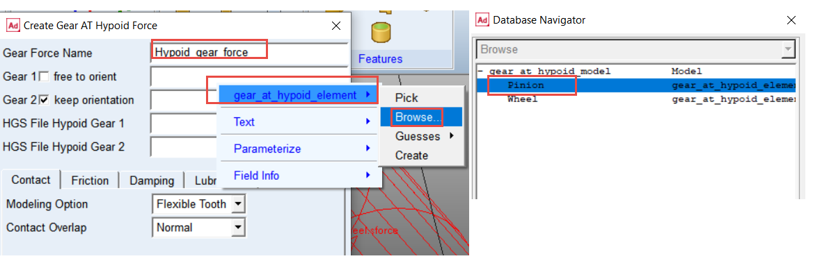
5. Similarly, right click the Gear 2 field and select gear_at_hypoid_element → Browse.
6. In the Database Navigator, select Wheel and Toggle On for keep orientation.
7. Right click and Browse in the HGS File Hypoid Gear 1 field, in the ../gears directory and select Pinion_030_03_02.hgs.
8. Similarly, Right click and Browse in the HGS File Hypoid Gear 2 field, in the ../gears directory and select Wheel_030_03_02.hgs.
9. In the Contact tab, set Modeling Option to Flexible Tooth.
10. Set Contact Overlap to Normal.
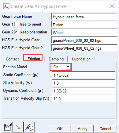
11. In the Friction tab, set the Friction Model to ON
12. Set the Friction Model to ON.
13. In the Damping tab, set value of Damping Rate Oil: 10.0
14. Click the OK button.
15. The Gear AT Force was created. The color of the Pinion and Wheel element has changed.

Note: | When defining gear force one short simulation is executed to compute backlash of the gear pair. Hereafter automatic reorientation of the gears takes places and following warning message pops up, which can be disregarded. 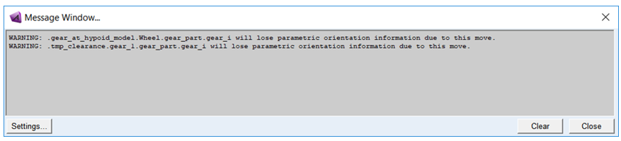 |
Reviewing Model
In order to get smooth contact pressure distribution over the flank you need to apply profile modification on the left flank of each gear.
To modify the tooth microgeometry of Hypoid Gear:
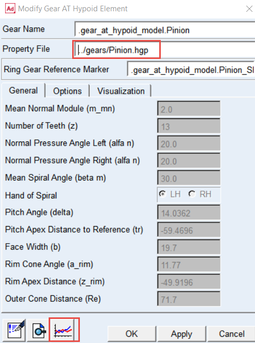
1. In the Gear AT menu, select Bevel/Hypoid Gear → Gear AT Element → Modify.
.png)
2. In the Modify Gear AT Hypoid Element window, right click and Browse for Pinion gear element and click Edit Property file button.
3. In the Modify Modifications of Hypoid Gear window, select Profile modifications left in option menu.
4. Select Quadratic option and set the value of Barreling (Ca) to 2.0E-02.
5. Click the Save hgp File button.
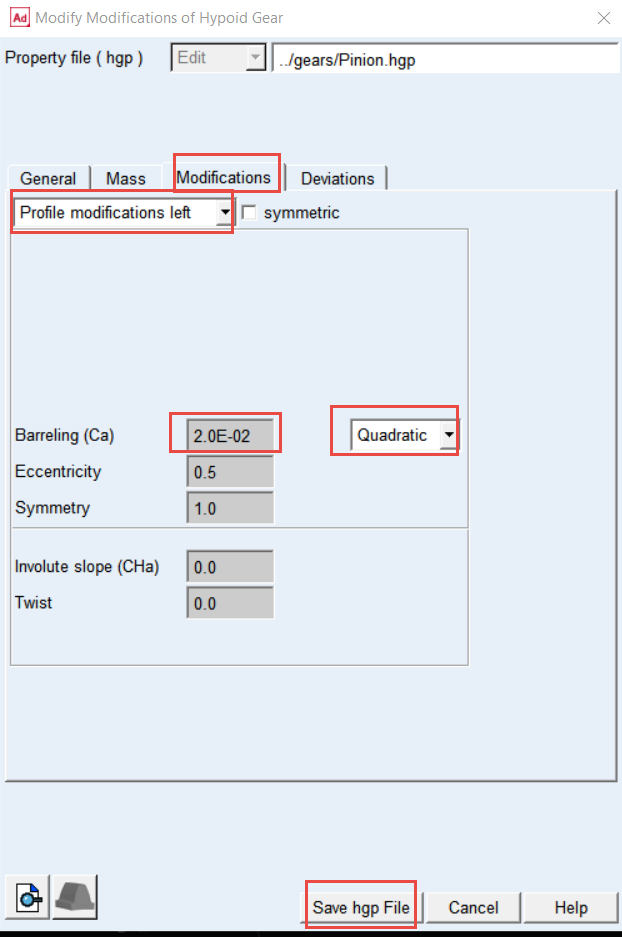
6. Modify the Wheel Element in the same way; select Quadratic option and set the value of Barreling (Ca) to 1.5E-02.
Setup Input Motion and Output Torque
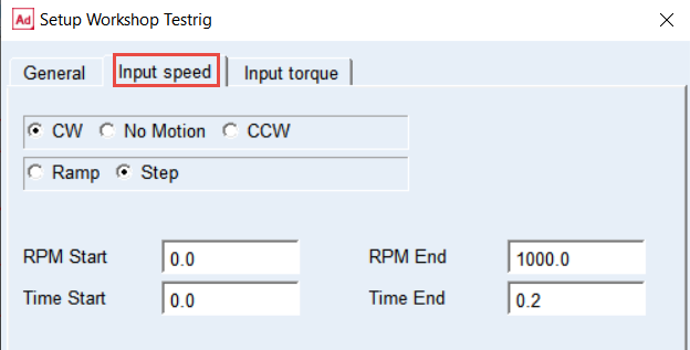
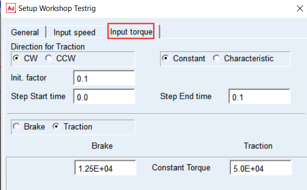
Before running simulation make sure that values of following testrig parameters are set as shown thus the driving motion function steps up from 0 to 1000 rpm and the output torque steps up from 10% to 100% of 2.0e5 Nmm. In this workshop model the output torque is defined from perspective of input, hence the torque value has to be divided by the gear ratio (4.0).
To setup Input Motion and Output Torque:
1. In the Gear AT menu, select Help → Getting Started → Setup Workshop Testrig.
.png)
2. In the Input speed tab, set the driving motion parameters as shown.
3. In the Input torque tab, set the loading torque parameters as shown.
Set the Solver Settings
To set the solver settings:
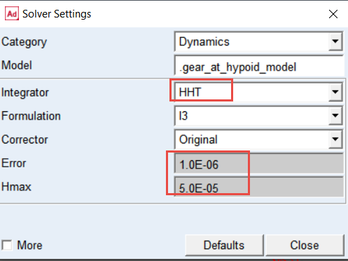
1. In the Settings menu, select Solver → Dynamics.
.png)
2. Select the Integrator: HHT.
3. Set the value of Error: 1.0E-06.
4. Set the value of Hmax: 5.0E-05.
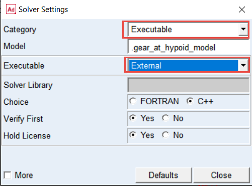
5. Change the Category to: Executable.
6. Set the Executable to: External.
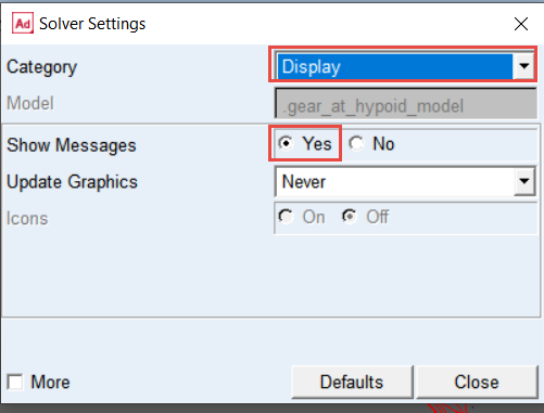
7. Change the Category to: Display.
8. Set the Show Messages to: Yes.
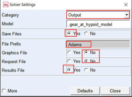
9. select Category: Output.
10. Set the Save Files: Yes.
11. Set the file prefix: Adams; this will be used for HGR result files for contact pattern post-processing.
12. Set the Graphics File: No.
13. Set the Request File: No.
14. Set the Results File: Yes.
15. select Category: Equilibrium.
16. Select the More options.
17. Set the value of Tlimit: 1.0E-02
18. Set the value of Alimit: 0.1.
19. Set the value of Maxit: 550.
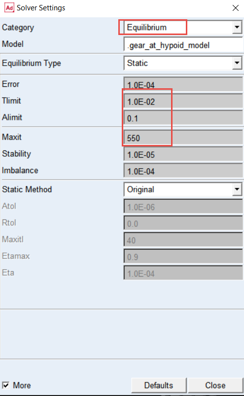
Note: | Using default solver settings for static equilibrium could result in failure to reach convergence for static and quasi-static simulation. |
Before you start the simulation, make sure the output of HGR files is switched on, to be able to make contact pattern post-processing:
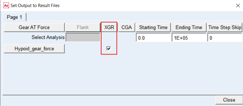
1. In the Gear AT, select Bevel/Hypoid Gear → Gear AT Results → Output Setings.
.png)
2. Ensure that the XGR toggle for Hypoid_gear_force is switched on.
Verifying Simulation Script and Run the Simulation
To verify the simulation script and run the dynamic simulation:
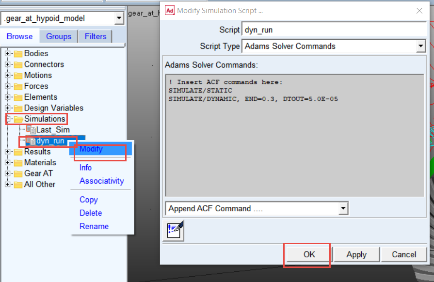
1. In the Model Browser double click on Simulations, right click on dyn_run and select Modify.
2. Verify the Solver Script and click the OK button.
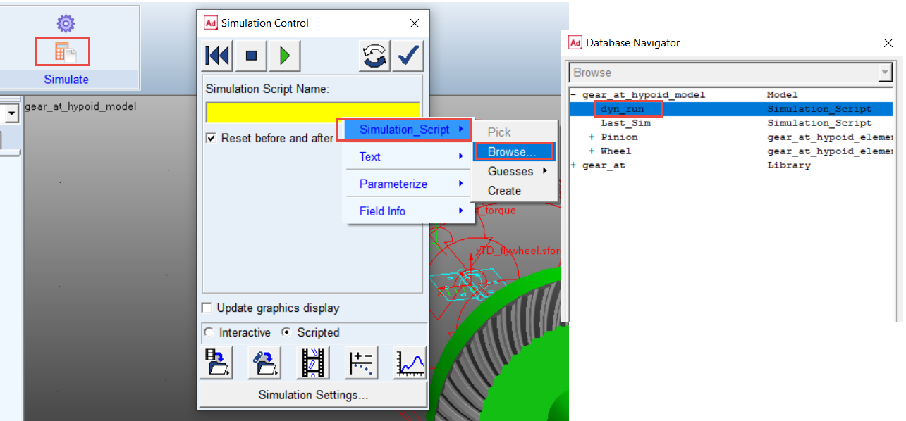
3. In the Simulation tab select Run a Scripted Simulation.
4. Right click on the Simulation Script Name field and select Simulation_Script → Browse.
5. In the Database Navigator window, select dyn_run as simulation script.
6. Click the Play button to start the simulation. The simulation will take a few minute to run.
Investigating the simulation results
In the Adams Postprocessor you can investigate the simulation results.
Make a plot of Pinion and Wheel Torque applied around its rotational axes:
1. Switch to Adams Postprocessor by pressing F8 on keyboard.
2. Select the Source: Requests.
3. Select the Request: Hypoid_gear_force_Total_Force_and_Torque.
4. Select the Components: TZ_Pinion and click Add Curves button.
5. Select the Components: TY_Wheel and click Add Curves button.
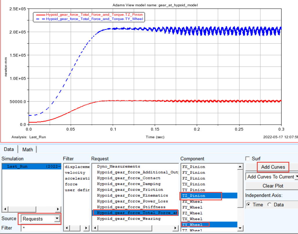
Note: | The resulting force and torque vectors are measured in so-called contact coordinate system denoted by “ccs” index on the Figure 4. In the Total Force and Torque request group the vectors represent sum of all components from contact stiffness, damping and friction. However, one can plot each component of total force or torque separately. For more information, refer Gear AT Results 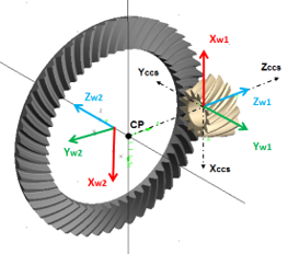 Figure 4 Gear_AT_Hypoid_contact_co-ord_sys |
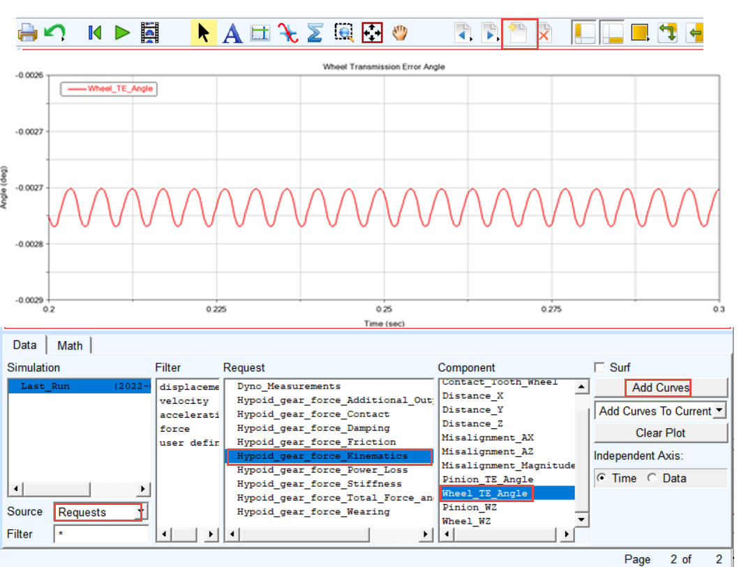
Make a plot of Wheel Transmission Error and create FFT plot to identify the tooth mesh frequency:
1. Create a new page.
2. Select the Request: Hypoid_gear_force_Kinematics.
3. Select the Component: Wheel_TE_Angle and click Add Curves button.
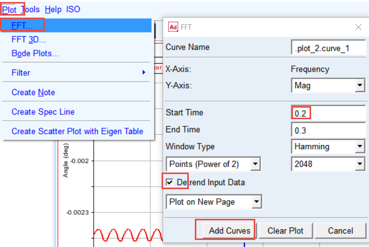
4. In the Menu point to the Plot and select: FFT.
5. Select Detrend Input Data toggle
6. Set the Start Time: 0.2.
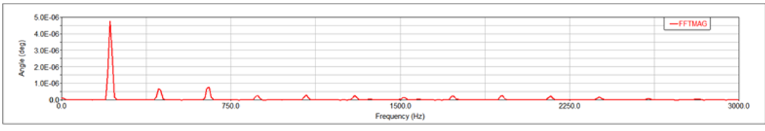
7. Click the Add Curves button.
8. The FFT plot is created. Zoom the horizontal axis from 0 to 1000 Hz.
Make plot of the tooth force magnitude applied on all teeth in contact:
1. Switch to Adams Postprocessor by pressing F8 on keyboard.
2. Select the Source: Requests
3. Select the Request: Hypoid_gear_force_Total_Force_and_Torque
4. Select the Components: from Tooth_M2 to Tooth_P2 and click Add Curves button
5. Zoom in the plot as appropriate.
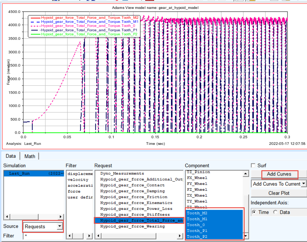
For Tooth Numbering Convention, refer Figure 5.
Make plot of maximum contact pressure over all teeth in contact:
1. Create new page
2. Select the Request: Hypoid_gear_force_Contact.
3. Select the Components: from Tooth_M2_Max_Pressure to Tooth_P2_Max_Pressure and click Add Curves button
4. Zoom in the plot as appropriate.
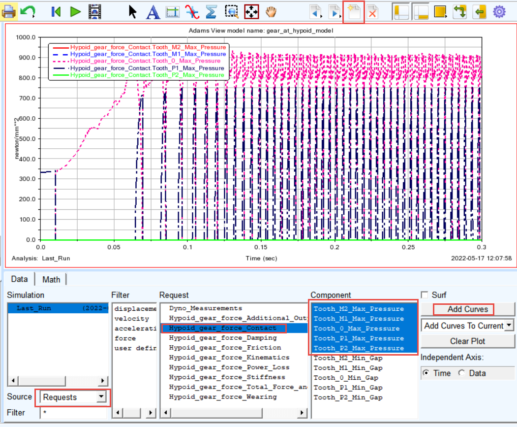
For Tooth Numbering Convention, refer Figure 5.
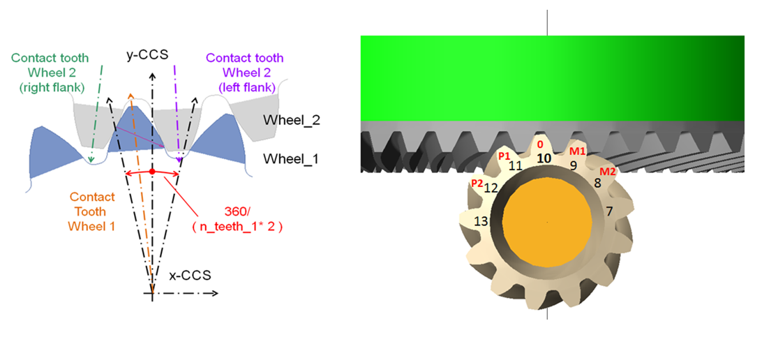
Figure 5 Tooth Numbering Convention
Plotting the contact pattern:
Before plotting the contact pattern, we need to find out the tooth in contact at particular time interval of interest. For tooth flank side definition, refer Figure 6
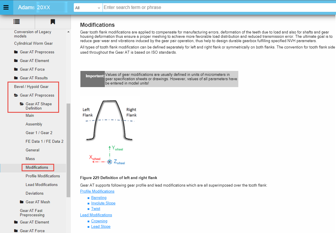
Figure 6 Tooth flank side definition
To plot the pinion and wheel contact tooth:
1. Create a new page.
2. Select the Request: Hypoid_gear_force_Kinematics.
3. Select the Component: Contact_Tooth_Pinion and Contact_Tooth_Wheel, click Add Curves button.
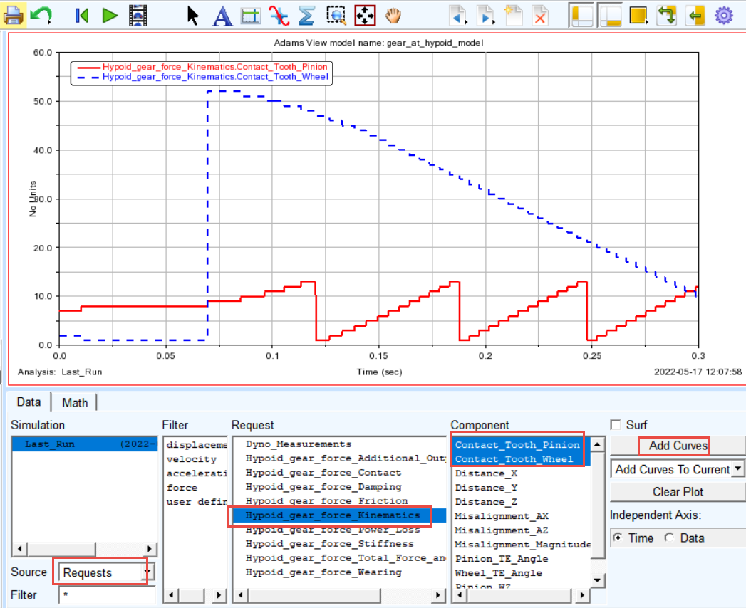
Note: | Figures shown here might look different to what you actually get while performing the workshop. You might get different plot of Contact_Tooth_Pinion and Contact_Tooth_Wheel curves depending on actual set up of gear meshing. |
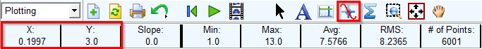
4. In the Menu bar point to the Plot tracking. Track the value of Pinion contact tooth close to time of 0.2 sec. From the tracking plot panel, we can see that Y value is equal to 3. This indicates the number of Pinion tooth on which the contact pressures can be displayed at the given time interval and that the side of contact is Left (PLUS) tooth flank.
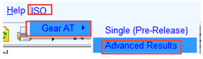
To plot the contact pattern in the Adams Postprocessor:
1. In the Adams Postprocessor menu, select ISO → Gear AT → Advanced Results.
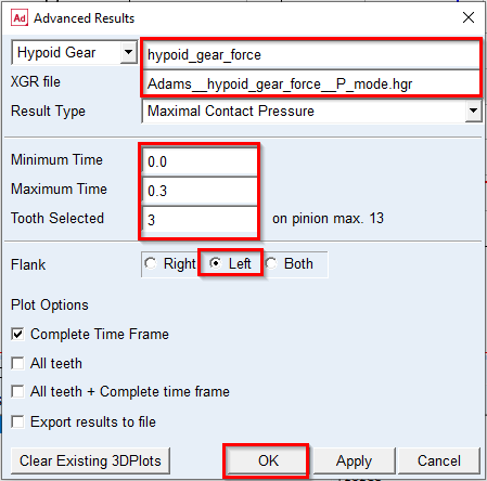
2. Select the Hypoid Gear: Hypoid_gear_force.
3. Browse in the working directory for the file: Adams__Hypoid_gear_force__P_mode.hgr (it does not matter which one of two files is selected, the both are loaded).
4. Set values for Minimum Time: 0.0; Maximum Time: 0.3.
5. Selected Tooth: 3.
6. Set the Flank radio button: Left for the contact flank (Left=Plus contact mode – Pinion contact tooth = 3).
7. Click the OK button.
8. The plots of the contact pattern results are created.
9. Explore contact pattern of the Plus (left) Flank of Tooth 3
10. Rotate the view to see the contact pattern from different views
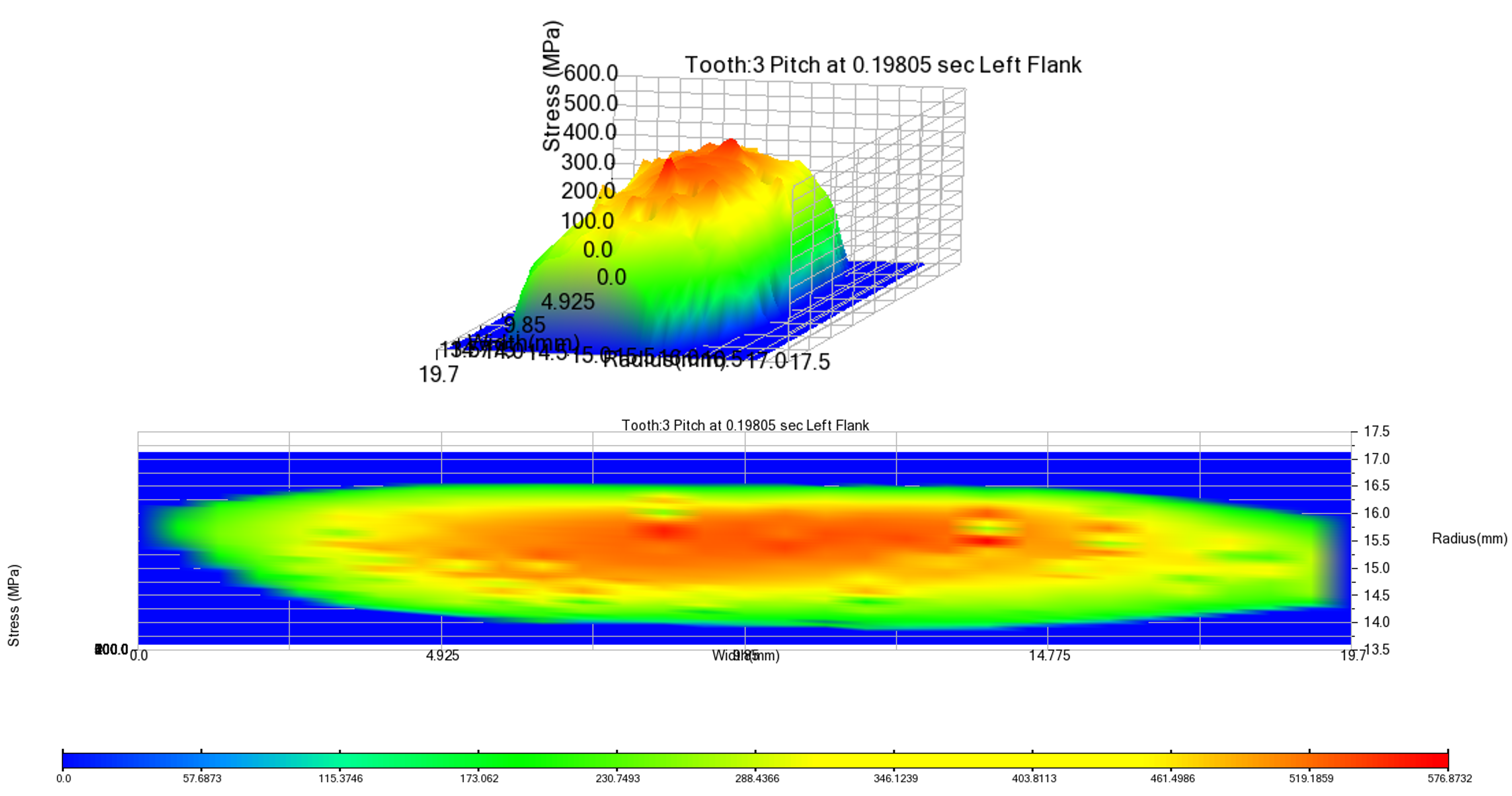
For advanced results, refer Figure 7.
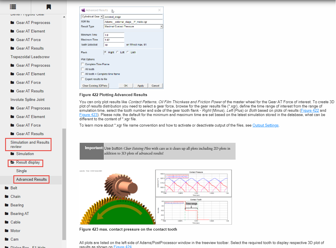
Figure 7 Advanced Results
Save your Work
To save your model:
1. Switch back to Adams View by pressing F8 on keyboard.
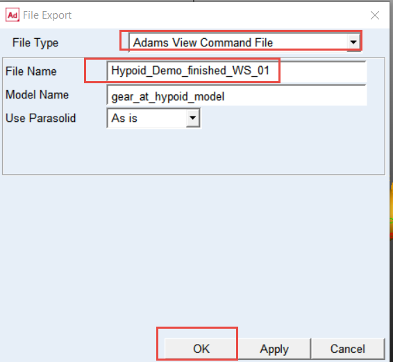
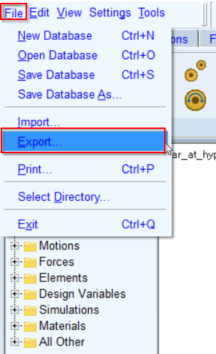
2. In the File menu, select Export...
3. Select the File Type: Adams View Command File
4. Enter File Name as Hypoid_Demo_finished_WS_01
5. Click the OK button.
6. The CMD file is exported to your working directory. You can use it in the next workshop.