Creating an Involute Spline Joint
During this tutorial, you will define a tooth profile from scratch using embedded profile generator. The first step is to enter all spline joint parameters in the shape definition step of Gear AT preprocessing which stores all geometrical data including profile in a spline property file, which is used as input for meshing and for spline joint element definition.
Next step is to generate FE meshes, then run Nastran SOL 101 and extract stiffness matrix to a spline stiffness file, which is then used for spline joint contact force definition. And finally, execute a simulation and investigate the results.
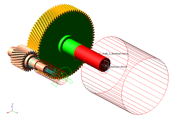
Figure 1 shows an involute spline joint that you are going to create.
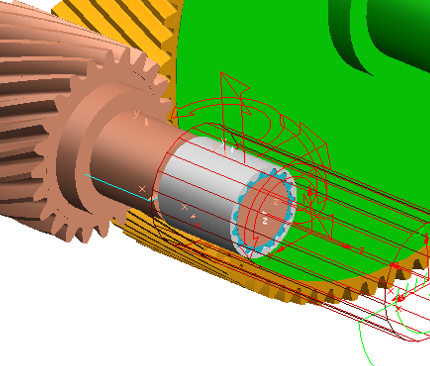
Figure 1 Involute Spline Joint
Prepare your Working Directory
To prepare your working directory:
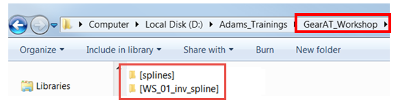
1. Navigate to your working directory in which you create new directory named as splines to store all files related to gears.
2. Create new directory named WS_01_inv_spline
3. Start Adams either from desktop or Windows Start menu → All Programs → Adams 202x.x.
Load Gear AT Plugin
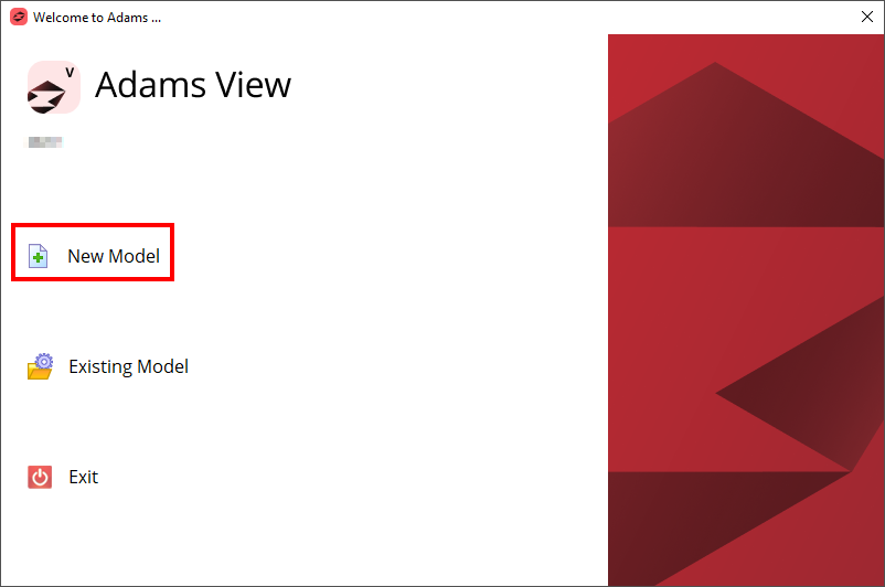
1. Under the Welcome dialog box, select New Model.
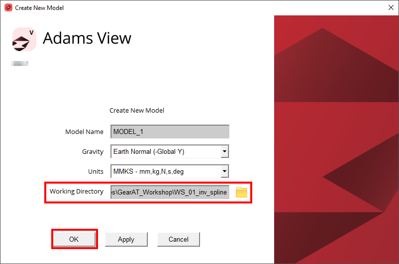
2. Set the Working Directory to WS_01_inv_spline.
3. Click the OK button.
Load the Workshop Model
To load a Workshop Start Model:
1. Click the Machinery tab on the Adams View ribbon and from the Gear AT container, click the icon to pop up Gear AT menu.
2. In the Gear AT menu → Help → Getting started → Spline Joint → Workshop Start Model.
.png)
3. The starting workshop model gear_at_cyl_spline_model was loaded.
Create the Shaft Tooth Profile
At this point there are no spline joint property files (*.ISP, *.ISD) available, so we have to prepare them from scratch. In this step we define a property file name (instead of browsing for an existing one) and enter all geometrical parameters manually. For tooth flank side definition, refer Figure 2
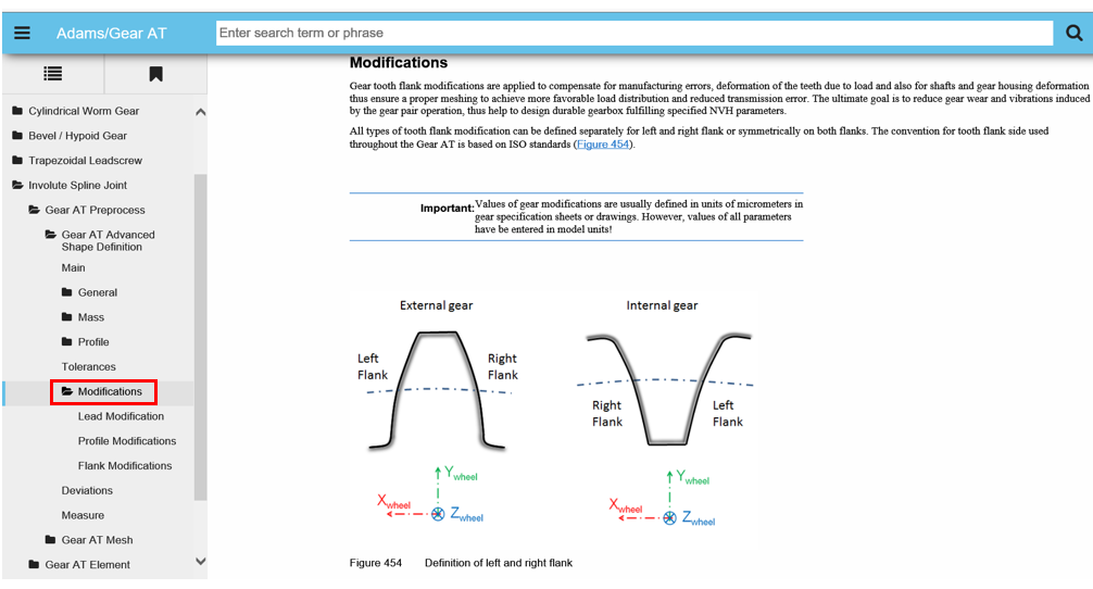
Figure 2 Tooth flank side definition
To create the Shaft tooth profile using Gear AT Shape Definition:
1. In the Gear AT menu, select Spline Joint → Gear AT Preprocess → Gear AT Advanced Shape Definition.
.png)
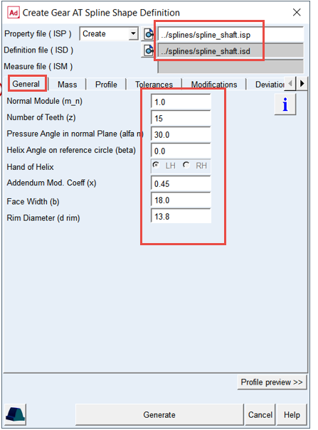
2. Type in the Property File name with relative path: ../splines/spline_shaft.
3. In the General tab, enter Normal Module (m_n): 1.0.
4. Set the value in Number of Teeth (z): 15.
5. Set the value in Pressure Angle in normal Plane (alfa n): 30.
6. Set the value in Helix Angle on reference circle (beta): 00.
7. Select Hand of Helix: LH.
8. Set the value in Addendum Mod. Coeff (x): 0.45.
9. Set the value in Face Width (b): 18.
10. Set the value in Rim Diameter (d rim): 13.8.
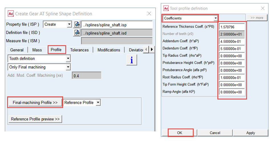
11. In the Profile tab, set the tool option menu to Tooth definition.
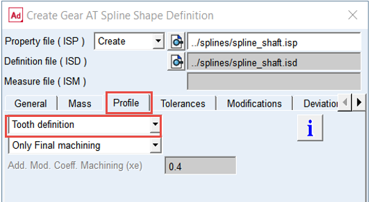
12. Click the Final-machining Tool >> button and under the Tool profile definition dialog box, set option menu to Coefficients and enter the values as shown below.
13. Click the OK button.
14. Click the Reference Profile preview >> button to review the tooth profile.
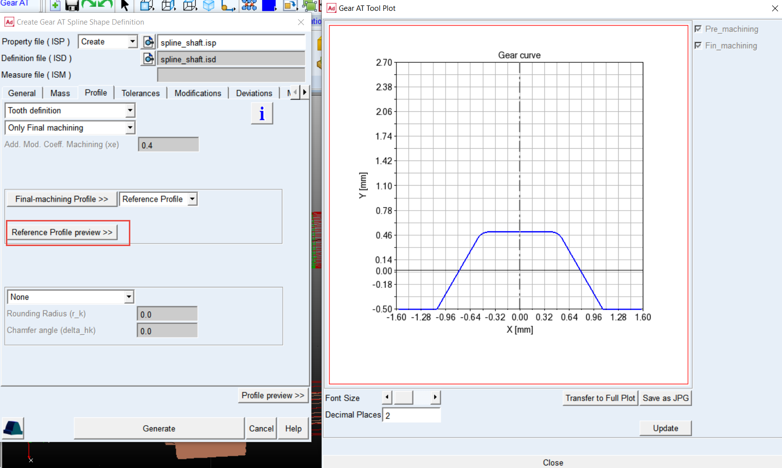
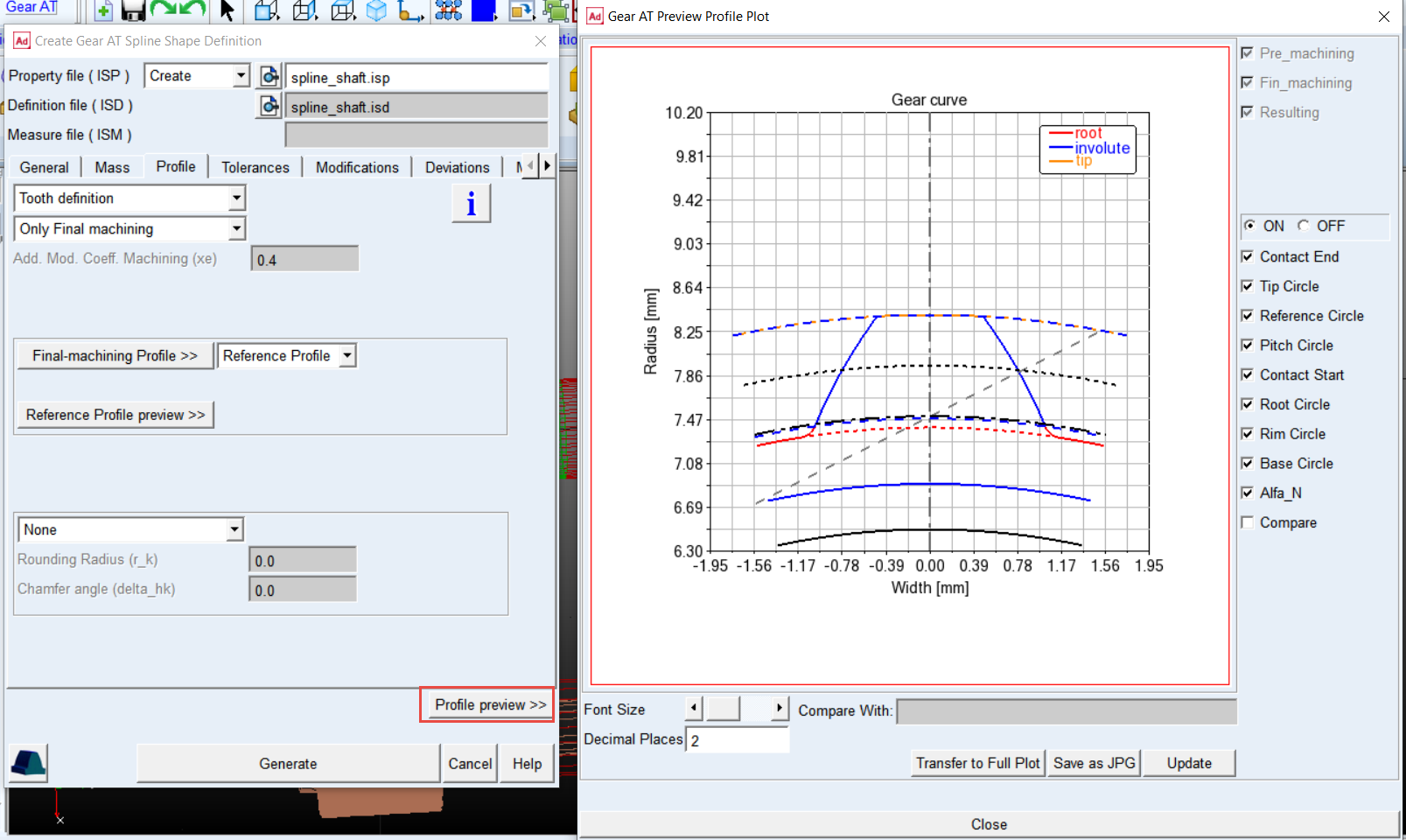
15. Click the Profile preview >> button to review the tooth profile.
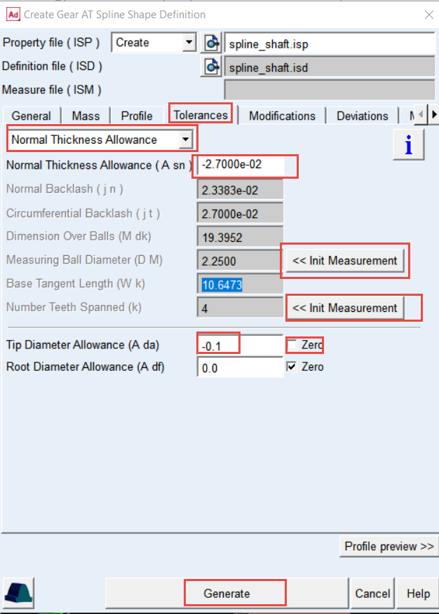
16. In the Tolerances tab, set the option menu to Normal Thickness Allowance.
17. Set the value of Normal Thickness Allowance (A sn): -2.7E-02.
18. Click << Init Measurement next to Measuring Ball Diameter (D M) field to set ideal ball diameter and get reasonable value of Dimension Over Balls (M dk).
19. Similarly, click << Init Measurement next to Number Teeth Spanned (k) field, so that the desired values will be populated.
20. Uncheck the Zero check box next to the Tip Diameter Allowance (A da) and set the value to: -0.1.
21. Click the Generate button. The spline_shaft.isd and spline_shaft.isp files were created in the ../splines directory.
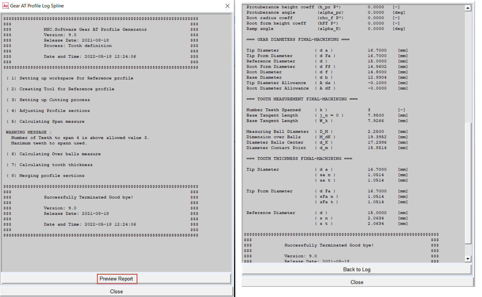
22. Click the Preview Report button to review calculated dimensions by the profile generator.
23. Close the Gear AT Spline Shape Definition dialog box by clicking the Cancel button.
Mesh the Shaft Tooth
Theory
The default FE Data settings have four options that defines the Meshing and the display options. Based on the dimensions of the tooth profile respective settings are generated for the selected option. These can be manually entered.
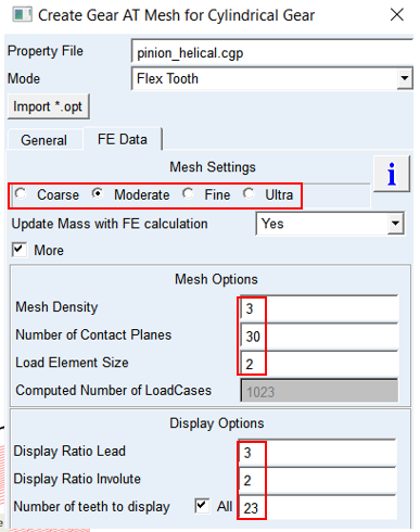
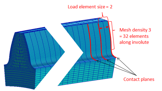
■Mesh Density defines number of elements along the contact line.
■The integer value of Number of Contact Planes is the number of equidistant sections along the lead direction of the tooth flank.
■Load element size is the number of FE element per contact plane.
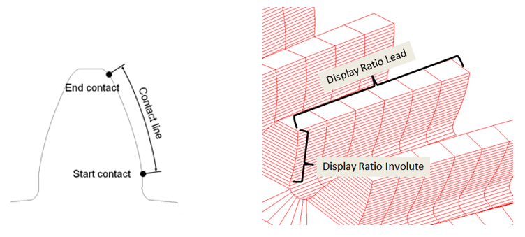
■Display Ratios are only for the visualization purpose. The values are the fractions of the number of elements in their respective directions.
In this step we preprocess FE mesh of a flexible tooth and generate shell file for Adams geometrical representation. Hereafter the stiffness matrix of a flexible tooth is generated with the help of Nastran embedded solver in Adams which is stored in *.iss file located in the splines folder. It will be referenced for the Spline joint force definition later.
To Create Nastran Mesh and Geometry of the Shaft
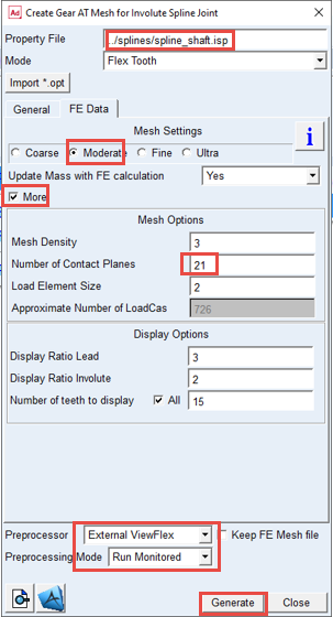
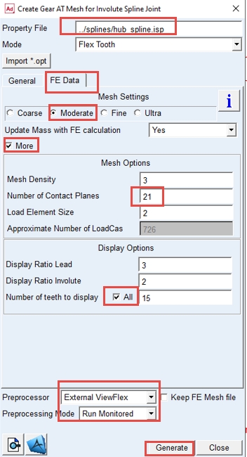
1. In the Gear AT menu, select Spline Joint → Gear AT Preprocess → Gear AT Mesh.
.png)
2. Right click and Browse the ../splines directory for the Property File: spline_shaft.isp.
3. Select the FE Data tab.
4. Select the option Moderate mesh.
5. Select the More toggle for more options.
6. Set the value in Number of Contact Planes: 21.
7. In the display option, select All for the Number of teeth to display toggle.
8. Select the Preprocessor: External ViewFlex
9. Select the Preprocessing Mode: Run Monitored
10. Click the Generate button, click Yes to confirm the start of preprocessing and wait till the SOL101 is completed.
Create the Hub Tooth Profile
To create the Hub tooth profile:
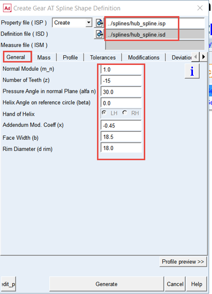
1. In the Gear AT menu, select Spline Joint → Gear AT Preprocess → Gear AT Advanced Shape Definition.
2. Type in the Property File name with relative path: ../splines/spline_ hub.
3. In the General tab, enter Normal Module (m_n): 1.0.
4. Set the value in Number of Teeth (z): -15.
5. Set the value in Pressure Angle in normal plane (alfa n): 30.
6. Set the value in Helix Angle on reference circle (beta): 0.
7. Select Hand of Helix: LH.
8. Set the value in Addendum Mod Coeff (x): -0.45.
9. Set the value in Face Width (b): 18.5.
10. Set the value in Rim Diameter (d rim): 18.
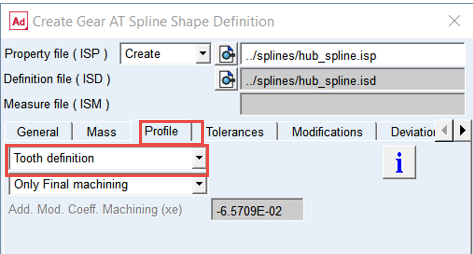
11. In the Profile tab, set the tool option menu to Tooth definition.
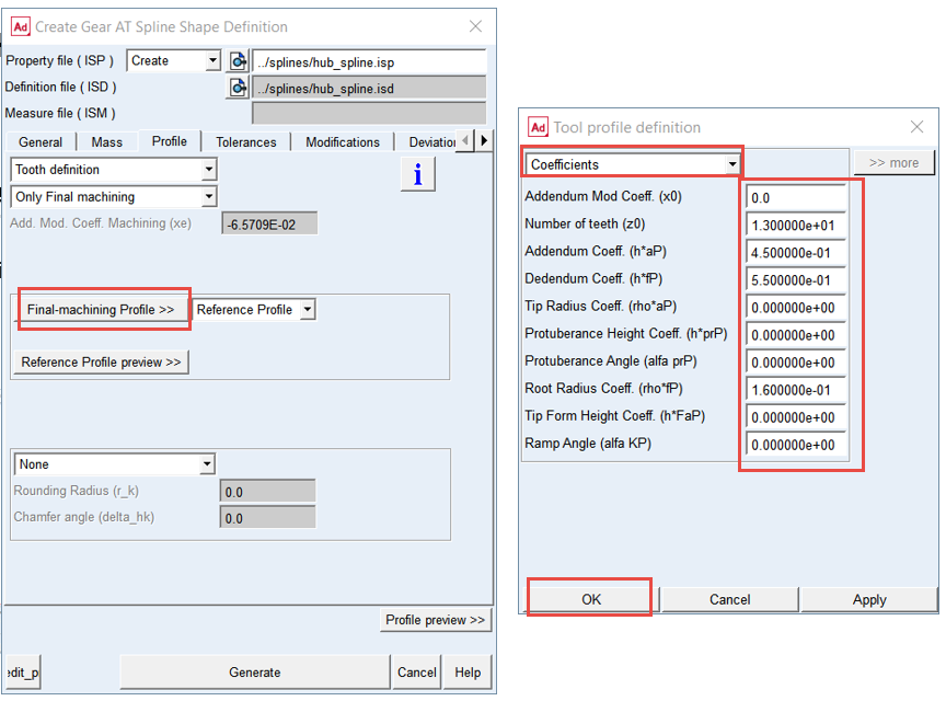
12. Click the Final-machining Tool >> button and under the Tool profile definition dialog box, set option menu to Coefficients and enter the values as shown below.
13. Click the OK button.
14. Click the Reference Profile preview >> button to review the tooth profile.
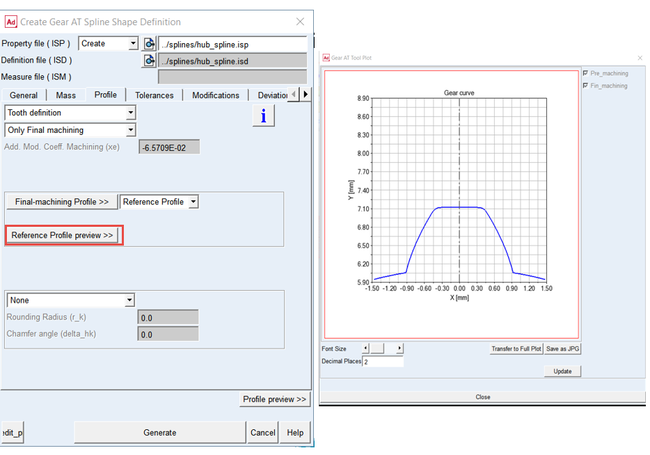
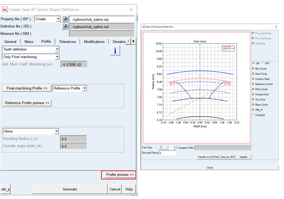
15. Click the Profile preview >> button to review the tooth profile.
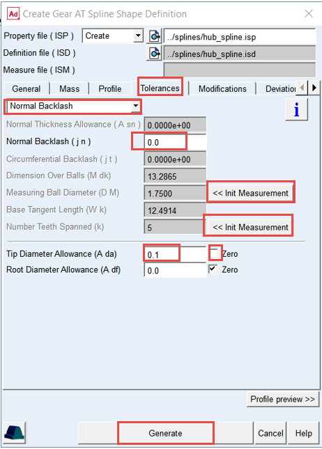
16. In the Tolerances tab, set the option menu to Normal Backlash.
17. Set the value of Normal Backlash (j n): 0.0.
18. Click << Init Measurement next to Measuring Ball Diameter (D M) field to set ideal ball diameter and get reasonable value of Dimension Over Balls (M dk).
19. Similarly, click << Init Measurement next to Number Teeth Spanned (k) field, so that the desired values will be populated.
20. Uncheck the Zero check box next to the Tip Diameter Allowance (A da) and set the value to: 0.1.
21. Click the Generate button. The hub_spline.isd and hub_spline.isp files were created in the ../splines directory.
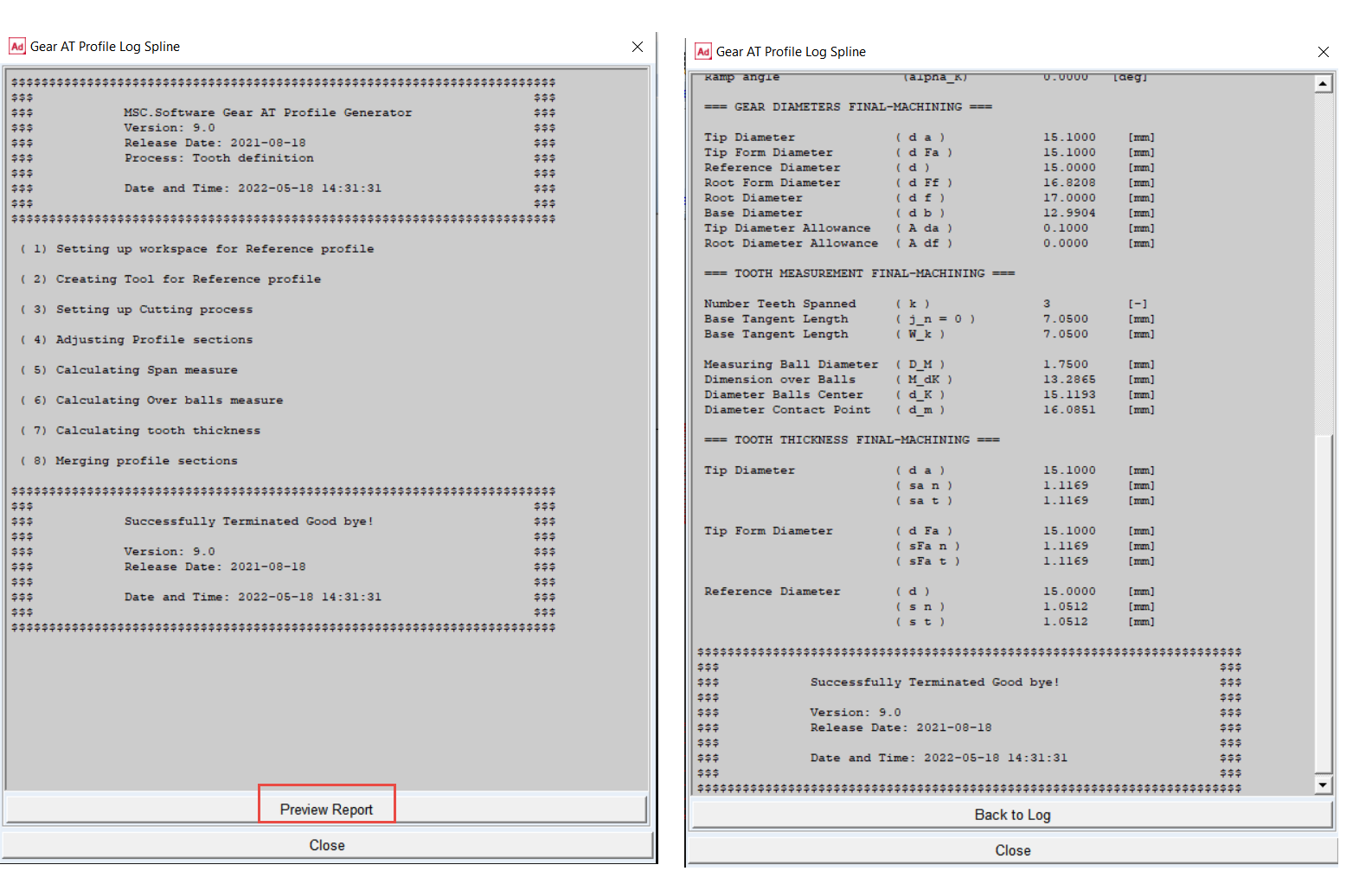
22. Click the Preview Report button to review calculated dimensions by the profile generator.
23. Close the Gear AT Spline Shape Definition dialog box by clicking the Cancel button.
Mesh the Hub Tooth
To create Nastran mesh and the geometry of the Hub tooth:
1. In the Gear AT menu point to Spline joint → Gear AT Preprocess → Gear AT Mesh.
.png)
2. Right click and Browse the ../splines directory for the Property File: spline_ hub.isp
3. Select the FE Data tab
4. Select the option Moderate mesh
5. Select the More toggle for more options
6. Set the value in Number of Contact Planes: 21
7. In the display option, select All for the Number of teeth to display toggle.
8. Select the Preprocessor: External ViewFlex
9. Select the Preprocessing Mode: Run Monitored
10. Click the Generate button, click Yes to confirm the start of preprocessing and wait till the SOL101 is completed.
Create the Shaft Gear AT Element
To create the Shaft spline element:
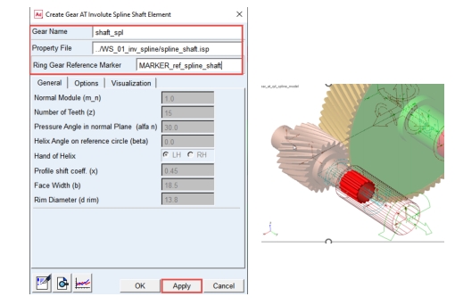
1. In the Gear AT menu, select Spline Joint → Gear AT Element → Gear AT Shaft Element → New.
.png)
2. Enter the Gear Name: shaft_spl
3. Right click and Browse the ../splines directory for the Property File name: spline_shaft.isp
4. In the Ring Gear Reference Marker field, Right click and select Marker → Browse.
5. In the Database Navigator window, select MARKER_ref_spline_shaft, under the input_shaft part.
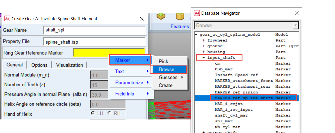
6. Click the Apply button.
7. The shaft_spl Gear AT Element has been created.
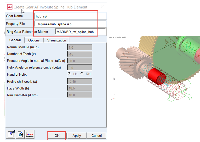
Create the Hub Gear AT Element
To create the Hub spline element:
1. In the Gear AT menu, select Spline Joint → Gear AT Element → Gear AT Hub Element → New.
.png)
2. Enter the Gear Name: hub_spl.
3. Right click and Browse the ../splines directory for the Property File name: spline_hub.isp.
4. In the Ring Gear Reference Marker field, Right click and select Marker → Browse.
5. In the Database Navigator window, select MARKER_ref_spline_hub, under the rotor_in part.
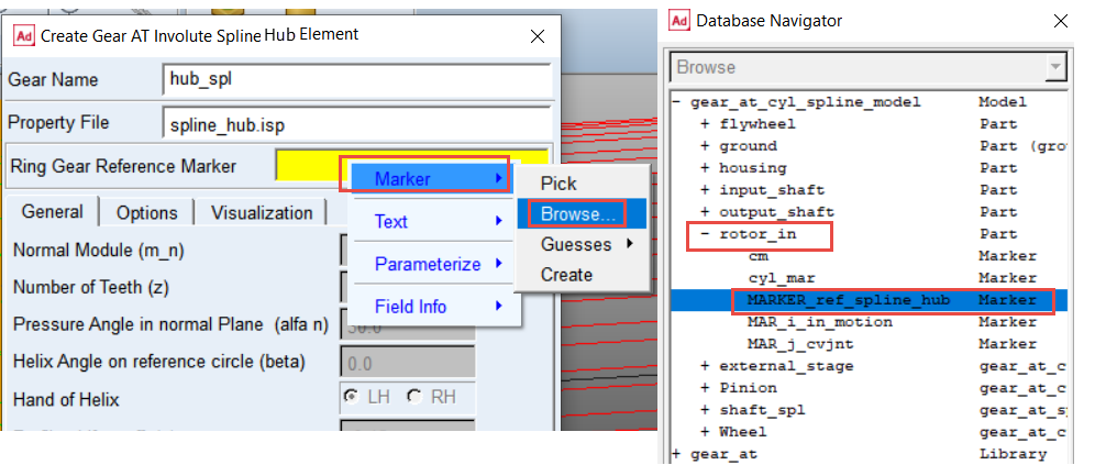
6. Click the OK button.
7. The hub_spl Gear AT Element has been created.
Create Gear AT Spline Joint Force
Theory – Damping Force
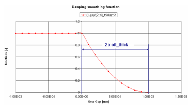
The function b is defined by:
 | (1) |
is used to smooth the damping.
There is no hydrodynamic damping, when b < 0:
 | (2) |
Hydrodynamic damping increases exponentially with decreasing oil film height. The introduction of the damping exponent d_exp:
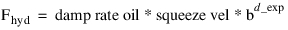 | (3) |
is used for this purpose. See Figure 3
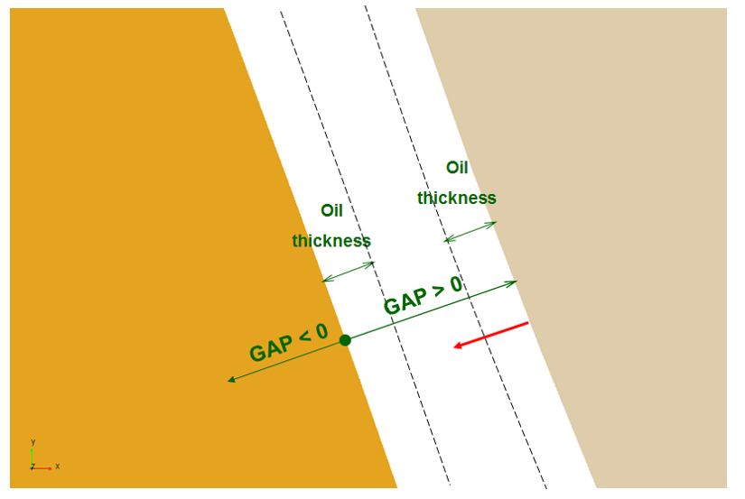
Figure 3 Oil Film Thickness
The structural damping force is made proportional to the contact force as shown by:

A value of 0.01 means, that the structural damping force is 1.0 percent of the elastic contact force.
Theory – Friction Force
The static friction coefficient  is usually somewhat higher than the dynamic friction
  coefficient. Step functions are used for smoothing the transitions. See Figure 4. Parameter of slip velocity (Vs) limits the region of sign change of the sliding velocity.
is usually somewhat higher than the dynamic friction coefficient. Step functions are used for smoothing the transitions. See Figure 4. Parameter of slip velocity (Vs) limits the region of sign change of the sliding velocity.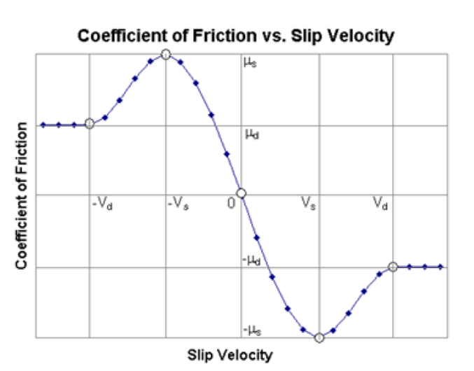
Figure 4 Coefficient of Friction vs, Slip Velocity
The combination of very small slip velocity (Vs) and high friction can reduce the performance of the integrator. You are advised to validate this selection through postprocessing of the sliding velocity.
Transition velocity (Vd) defines the start of the region, where the dynamic friction is constant. A small difference between slip velocity (Vs) and transition velocity (Vd) could also lead to numerical issues of the integrator.
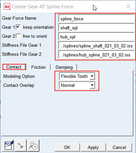
To Create the Spline Joint Contact Force:
1. In the Gear AT menu, select Spline Joint → Gear AT Force → New.
.png)
2. Enter the Gear Force Name: spline_force.
3. For Gear 1, Right click → gear_at_spline_i_shaft_element → Browse and select shaft_spl.
4. Select the keep orientation for the Gear 1.
5. For Gear 2, Right click → gear_at_spline_i_hub_element → Browse and select hub_spl.
6. Check the toggle OFF for the Gear 2 to free to orient.
7. Right click and Browse for the ISS File of Gear 1 in the ../gears directory: spline_shaft_021_03_02.iss.
8. Right click and Browse for the ISS File of Gear 2 in the ../gears directory : hub_spline_021_03_02.iss.
9. In the Contact tab, set the Modeling Option to Flexible Tooth.
10. Set Contact Overlap to Normal.
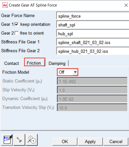
11. Go to Friction tab and set the Friction Model to Off.
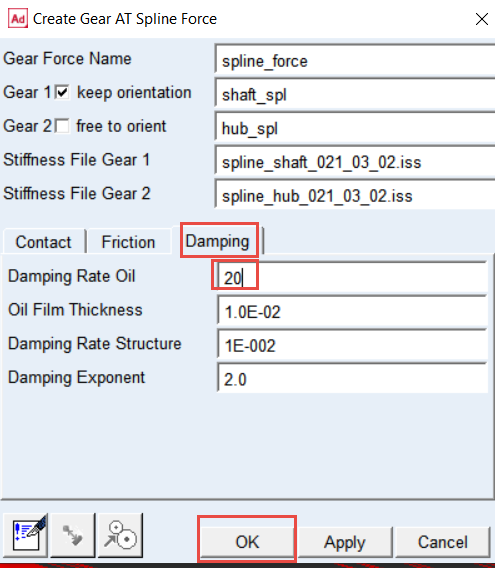
12. Go to Damping tab and set the value of Damping Rate Oil: 20.0.
13. Click the OK button.
14. The Gear AT Spline Joint Force element has been created.
Note: | The color of the shaft_spl and hub_spl Gear AT Element has changed. The color coding is set according to the role of a gear. |
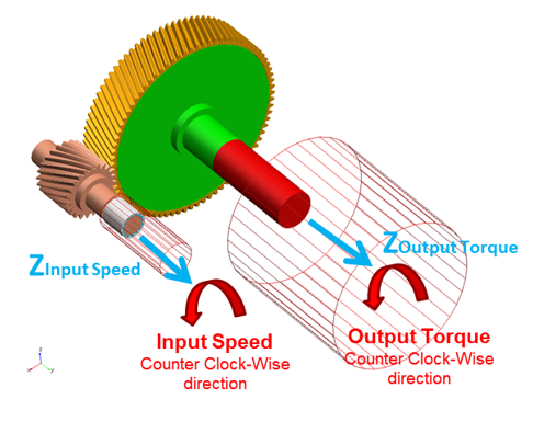
Setup Input motion and Output Torque
Before running simulation make sure that values of following testrig parameters are set as shown thus the driving motion function is set up to constant value of 5000 rpm and the output torque is set up to 100% of 2.5e5 Nmm.
To set Input motion and Output Torque:
1. In the Gear AT menu, select Help → Getting Started → Setup Workshop Testrig.
.png)
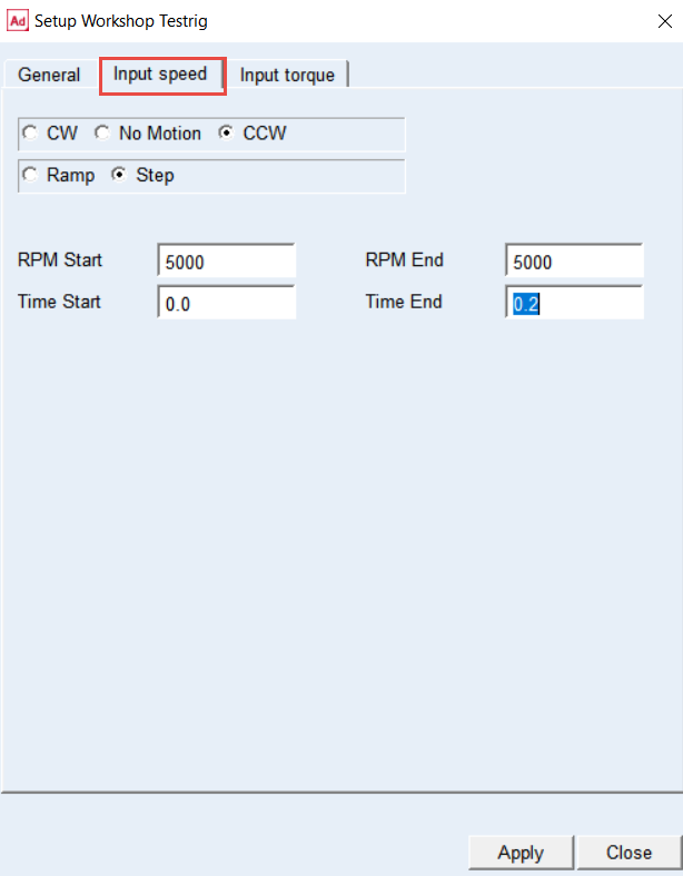
2. Go to Input speed tab and set the driving motion parameters as shown.
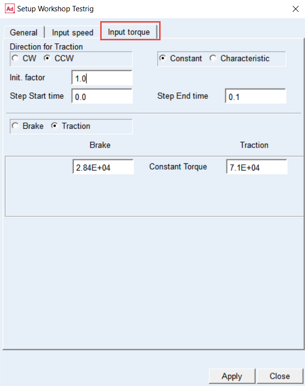
3. Go to Input torque tab and set the loading torque parameters as shown.
4. In the Model Browser navigate to Connectors, Right click on JOINT_inp_shaft_2_rotor and select (De)activate.
5. In the Activate/Deactivate window, uncheck the Object Active and Object’s Dependents Active option.
6. Click the OK button.
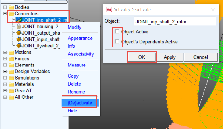
Note: | Before running simulation make sure that the constant velocity joint which connects the Input_shaft to the Rotor_in part is deactivated so the Spline Joint contact force transmits the torque instead of the joint. |
Modify Motion
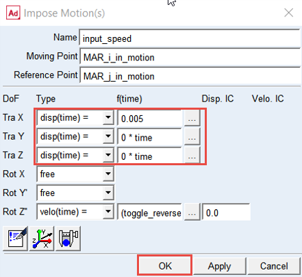
After deactivation of the JOINT_inp_shaft_2_rotor the Rotor_in part is free to move along axial direction. Modify general motion and remove this degree of freedom by definition of zero displacement along Tra Z of the motion reference marker.
To see the effect of spline joint angular misalignment, define radial offset of the motion by 0.005 mm along Tra X:
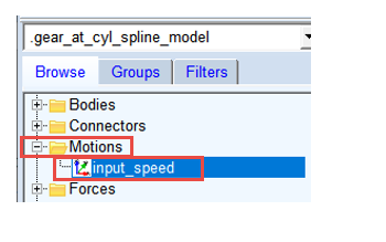
1. In Model Browser under Motions section, double click on the input_speed.
2. In the Impose Motion(s) window, enter following values as shown below.
3. Click the OK button.
Apply Tooth Modifications on the Shaft Spline
Before you run the dynamic simulation you must define microgeometry modifications to the shaft spline element.
To apply tooth modifications on shaft spline element:
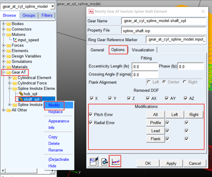
1. In the Model Browser under Gear AT section, right click on shaft_spl and select Modify.
2. In Options tab, ensure that all modifications and errors are applied.
3. If the Modifications and Errors are not applied switch them ON.
4. Click the Edit Property File button to enter microgeometry parameters.
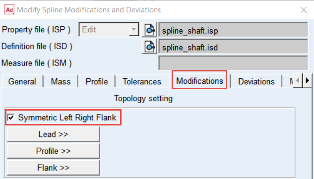
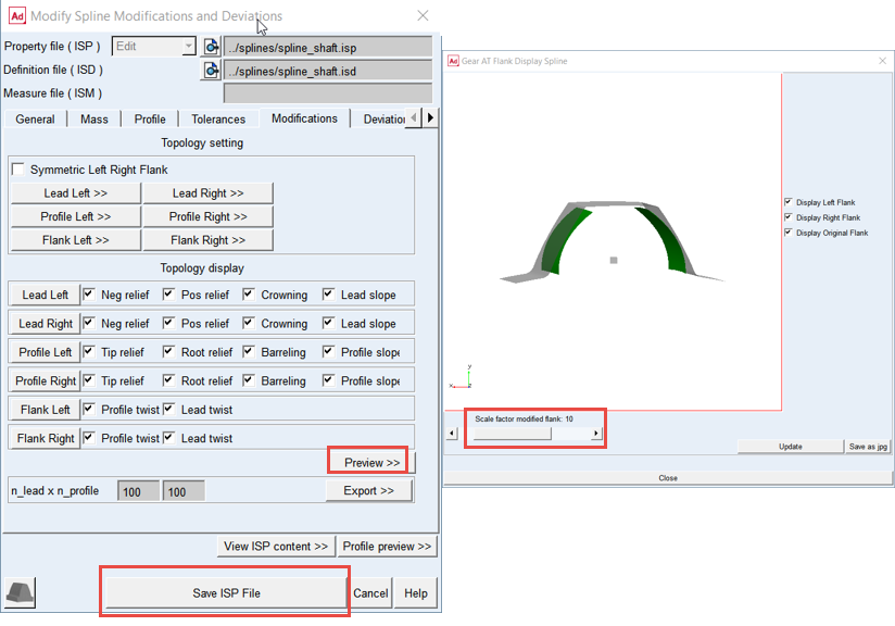
5. In the Modify Spline Modifications and Deviations window, go to the Modifications tab and toggle ON Symmetric Left Right Flank to apply the same modifications on both flanks.
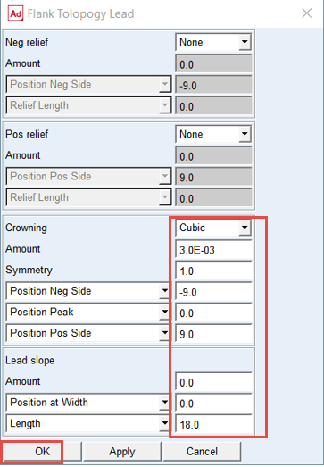
6. Click the Lead >> button and enter the values as shown below in the Flank Topology Lead window. Click the OK button.
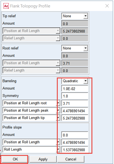
7. Click the Profile >> button and enter the values as shown below in the Flank Topology Profile window. Click the OK button.
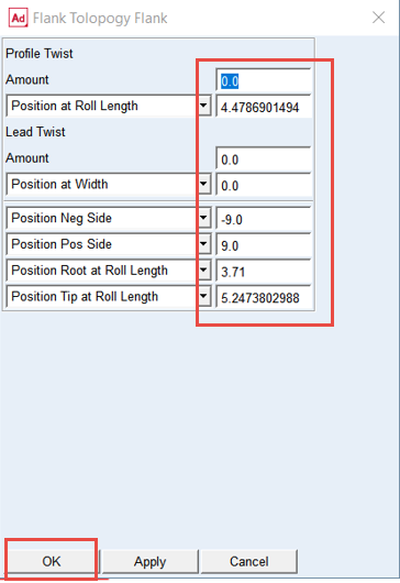
8. Click the Flank >> button and enter the values as shown below in the Flank Topology Flank window. Click the OK button.
9. Click the Preview >> button.
10. To investigate the modifications, apply Scale factor, use the zoom and rotate shortcuts.
11. Click the Save ISP File button. The spline_shaft.isd and spline_shaft.isp files were updated in the ../splines directory.
Set the Solver Settings
To set the solver settings:
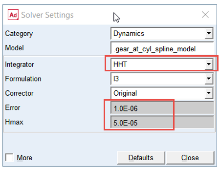
1. In the Settings menu, select Solver → Dynamics.
.png)
2. Select the Integrator: HHT.
3. Set the value of Error: 1.0E-06.
4. Set the value of Hmax: 5.0E-05.
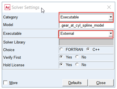
5. Change the Category to: Executable.
6. Set the Executable to: External.
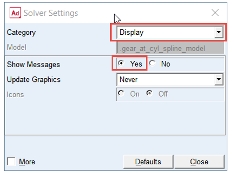
7. Change the Category to: Display.
8. Set the Show Messages to: Yes.
 W
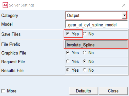
W 9. Select Category: Output.
10. Set the Save Files: Yes.
11. Set the File prefix: Involute_Spline; this will be used for ISR result files for contact pattern post-processing.
12. Select Category: Equilibrium.
13. Select the More options.
14. Set the value of Error: 1.0E-02.
15. Set the value of Tlimit: 1.0E-02.
16. Set the value of Alimit: 1.0E-02.
17. Set the value of Maxit: 500.
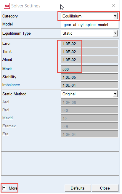
Note: | Using default solver settings for static equilibrium could result in failure to reach convergence for static and quasi-static simulation. |
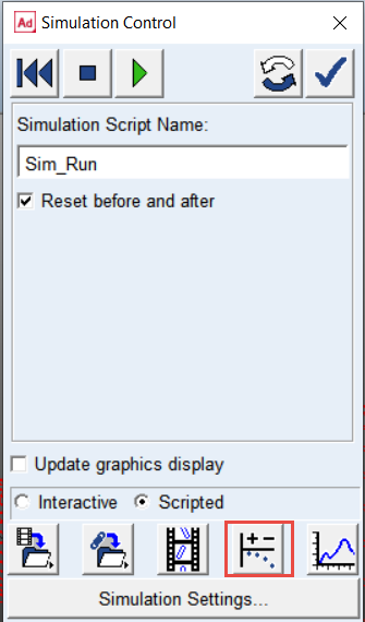
Verify Simulation Script and Run the Simulation
To verify the simulation script and run the dynamic simulation:
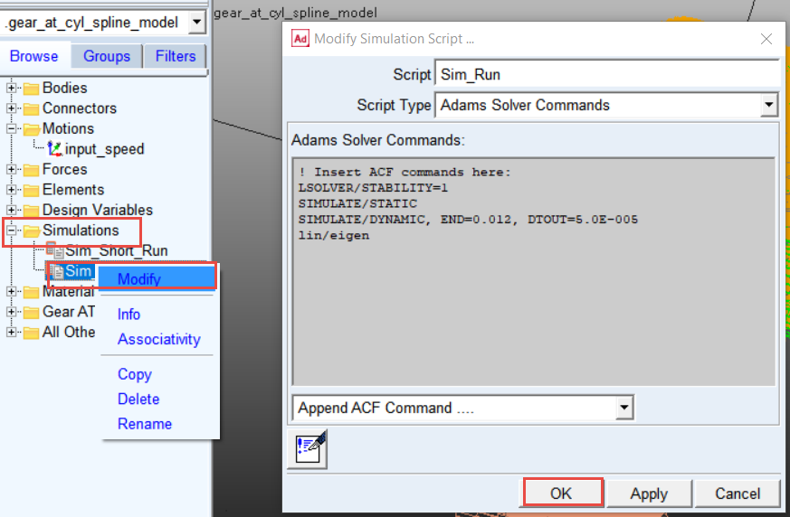
1. In the Model Browser double click on Simulations, right click on Sim_Run and select Modify.
2. Verify the Solver Script and click OK button.
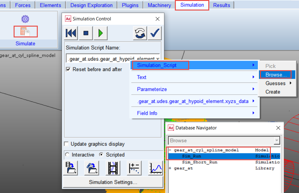
3. In the Simulation tab select Run a Scripted Simulation.
4. Right click in Simulatoin Script Name, select Simulation_Script → Browse.
5. From gear_at_cyl_spline_model, double click Sim_Run as solver script.
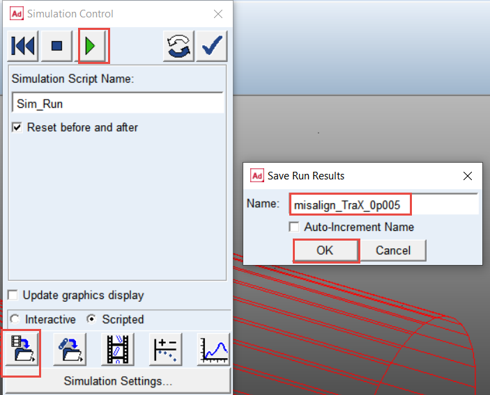
6. click the play button. The simulation will take a few minutes to run.
7. Save simulation as misalign_TraX_0p005 and click the OK button.
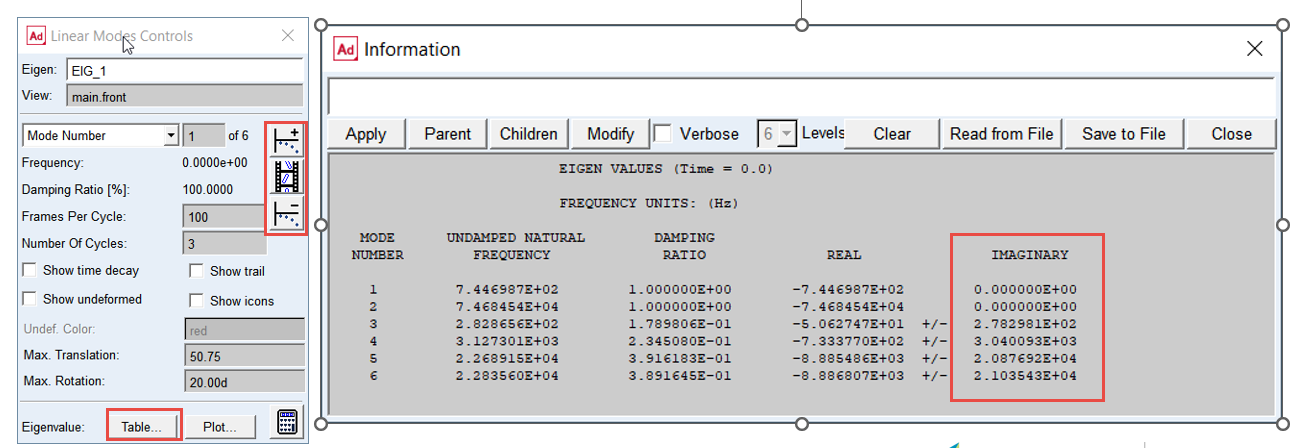
Investigate Results of Linear Analysis
Explore results of linear analysis and make sure the system is not over-damped:
1. From the Simulation control dialog box select Switch to linear modes controls.
2. Animate system modes.
3. Display eigen values in tabular form.
4. Make note of damped natural frequencies (imaginary component), make sure those have non-zero values.
Investigate the Simulation Results
In the Adams Postprocessor you can investigate the simulation results.
Note: | The results are reported in so-called in element coordinate system denoted by “s” index for shaft spline and “h” index for hub spline element on as shown on the Figure 5. In the Total Force and Torque request group the vectors represent sum of all components from contact stiffness, damping and friction. However, one can plot each component of total force or torque separately. For more information, refer Gear AT Results. 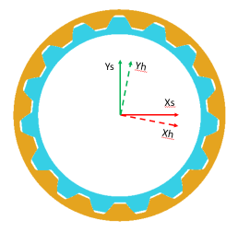 Figure 5 Gear_AT_Spline_gear_contact_co-ord_sys |
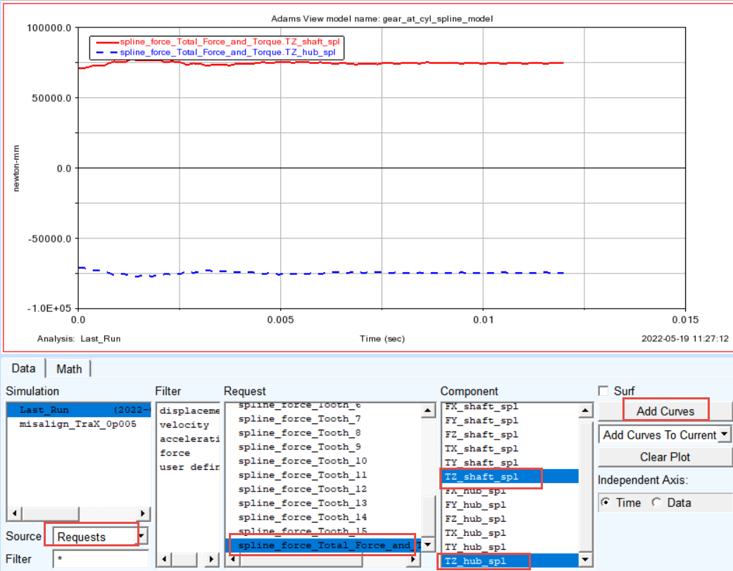
To Make plot of torque applied on Hub and Shaft:
1. Switch to Adams Postprocessor by pressing F8 on keyboard.
2. Select the Source: Requests.
3. Select the Request: spline_force_Total_Force_and_ Torque.
4. Select the Components: TZ_shaft_spl and click Add Curves button.
5. Select the Components: TZ_hub_spl and click Add Curves button.
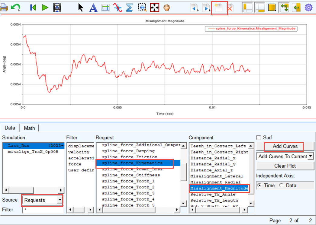
To make a plot of Misalignment Magnitude:
1. In Adams Postprocessor create a new page.
1. Select the Request: spline_force_Kinematics.
1. Select the Component: Misalignment Magnitude and click Add Curves button.
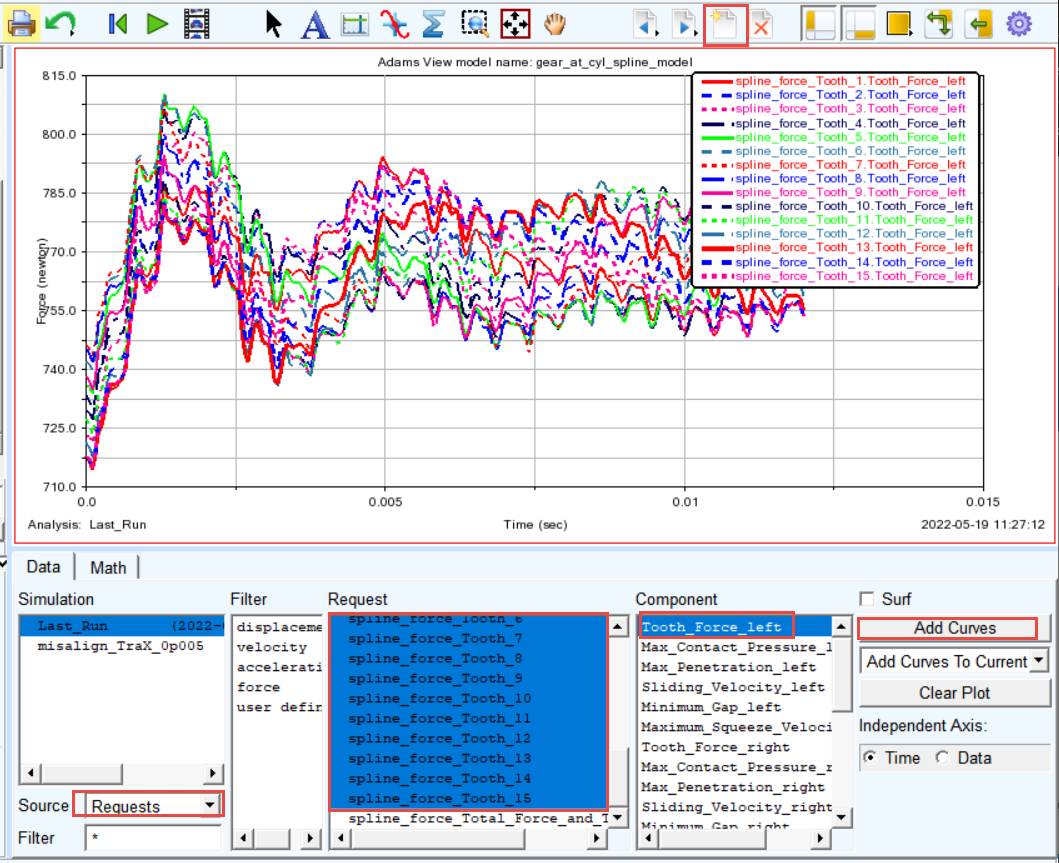
To make a plot of Tooth Force:
1. In Adams Postprocessor create a new page.
2. Select the Request: spline_force_Tooth_1 up to spline_force_Tooth_15
3. Select the Components: Tooth_force_left and click Add Curves button.
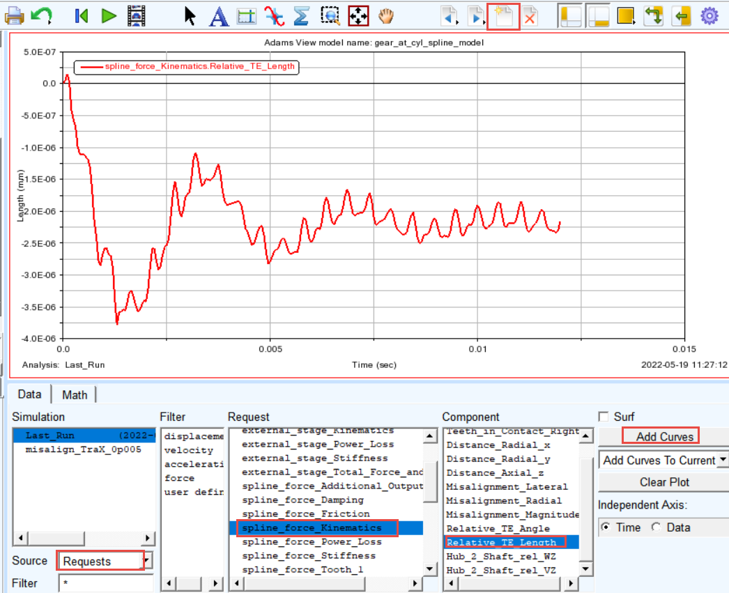
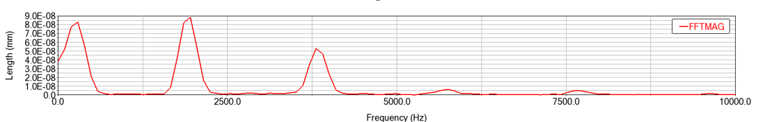
To make a plot of Wheel Transmission Error and create FFT plot to identify the tooth mesh frequency:
1. In Adams Postprocessor create a new page.
2. Select the Request: spline_force_Kinematics.
3. Select the Component: Relative_TE_Length and click Add Curves button.
4. In the Plot menu, select: FFT.
5. Select Detrend Input Data toggle
6. Set the Start Time: 6.0E-03
7. Click the ADD Curves button.
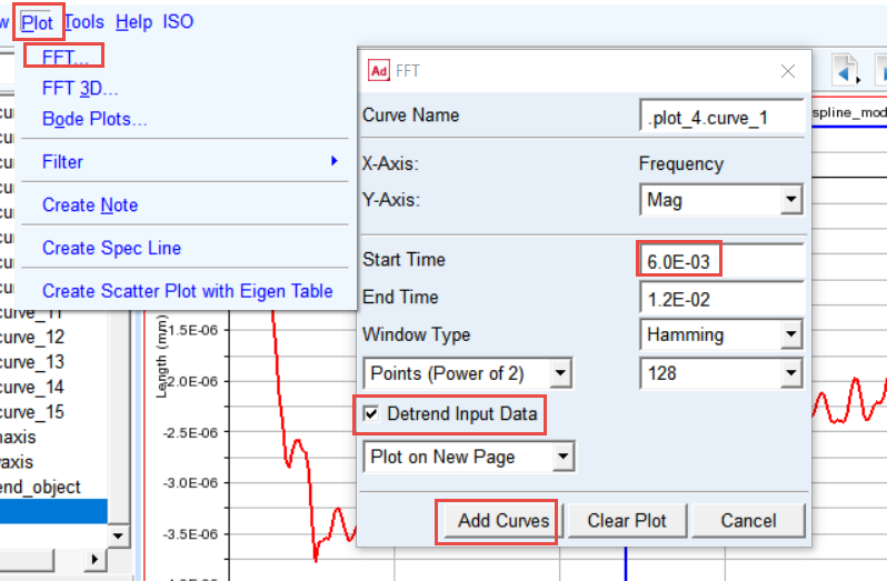
8. The FFT plot is created. Zoom the horizontal axis from 0 to 10000 Hz.
Save your Work
To save your model:
1. Switch to Adams View by pressing F8 on keyboard.
2. In the File menu, select Export...
3. Select the File Type: Adams View Command File.
4. Enter File Name as WS_involute_spline_joint_finished.
5. Click the OK button.
6. The CMD file is exported to your working directory.
.png)
Optional Tasks
1. Edit shaft_spline and hub_spline elements by setting all modifications to be switched on. Save simulation as “with_modifications”.
2. Edit shaft_spline and hub_spline elements by setting the pitch_error to be switched on. Save simulation as “with_pitch_error”.
3. Compare results with baseline simulation