Creating an Angle Measure
Now you create an angle measure to ensure that the handle pushes down far enough to engage the latch. When the latch engages, you know that the handle has toggled “overcenter” and is now capable of holding the latch in a secure position. It’s similar to using vice grips--the point where the vice clamps down on the material is the toggle point.
Creating the angle measure involves picking markers located at the points defining the angle, in this case POINT_8, POINT_3, and POINT_8_2. Adams View automatically defines markers at the center of mass of all parts and at vertices and endpoints of geometry. Adams View also creates markers automatically when you constrain objects, like when you add a joint between parts. Therefore, there can be several markers at one location. When you create the angle measure you only need to pick one marker for each location. However, you must make sure that the marker you pick belongs to the appropriate part.
To create an angle measure:
1. Click the Design Exploration tab on the Adams View ribbon.
2. From the Measures container, click Angle Measure tool  . Click Advanced button.
. Click Advanced button.The Angle Measure dialog box appears.
3. In the Measure Name text box, enter the measure name as overcenter_angle.
4. Right-click the First Marker text box, point to Marker, and then select Pick.
5. Pick the markers to enter in your measure as shown in row 1 of Table 1 and illustrated in Figure 2.
Note: | Do not pick markers that belong to ground, because markers used in the angle measure must move with the latch. |
6. Repeat the above two steps for the Middle Marker and Last Marker
.
Angle points: | Marker location: | Coordinate values: |
|---|---|---|
First Point | Any marker at POINT_8 | -1, 10, 0 |
Middle Point | Any marker at POINT_3 (angle vertex) | 2, 8, 0 |
Last Point | Any marker at POINT_8_2 | -6, 5, 0 |
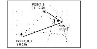
Figure 2 Graphical Representation of overcenter_angle
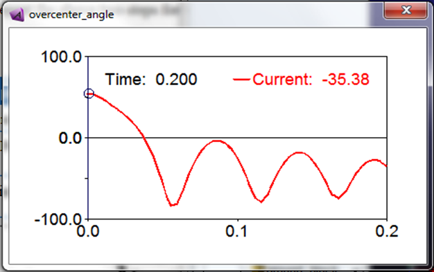
7. Select OK to display your angle measure strip chart as shown next: