Integration with Driving Simulators
Integration with VI-grade driving simulator
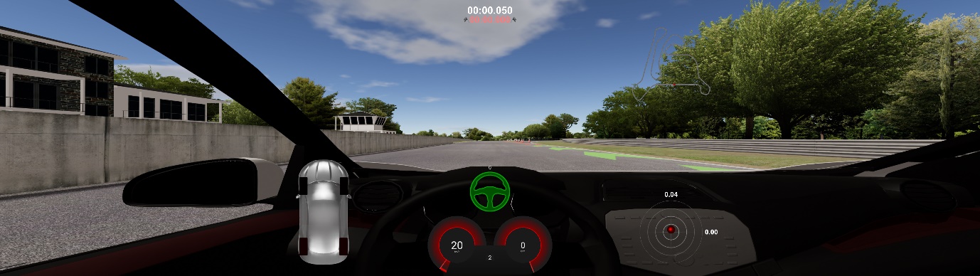
This section covers how to setup SIMulation Workbench (SimWB) and VI-DriveSim to use Adams in a VI-grade driving simulator. Also, it explores the process of creating an initial test scenario and executing a simulation.
To learn how to prepare and export an existing Adams Car model as an FMU suitable for SimWB and VI-DriveSim, see Getting Started with Adams Real Time
Section written for:
■Adams 2024.1
■VI-DriveSim 2023.1
■SimWB 2022.2
■Concurrent RedHawk 8.x RTOS
■Desktop simulator
License requirements
License requirements for using Adams as vehicle model in a VI-grade simulator.
For Adams:
■Standard set of Adams Car licenses, same as when running the model offline.
■Adams Controls license
■Adams Solver SMP license
■Adams Real Time OS license
VI-DriveSim, additions:
■VI-DriveSim External Physics (provided by VI-grade)
SimWB, additions:
■Adams FMU import license (provided by Concurrent)
Note: | Adams should be installed locally on the Concurrent box. |
Create and set up a project in SimWB
To create and setup a new Project in SimWB, follow the steps in the VI-DriveSim 2023.1 documentation chapter 3.1.1 “Creating a Project with VI-DriveSim and SimWB” and chapter 3.1.2 “Creating a RTDB with VI-DriveSim and SimWB”. Additional notes:
■For this guide, give the project the name “Adams_drivesim”
■When creating the RTDB, give it the name “ADAMS”. Any name is valid, but this guide assumes that the RTDB is named “ADAMS”.
Update the VI-DriveSim environment
Some additional environment variables are necessary to add to your VI-DriveSim environment file(s) located in ../usr/local/ccursim/projects/__project.<project_name>/ENV. The table below lists the required variables and a few optional variables.
Make a copy of the existing environment file “vidrivesim_conf.config” and add the appropriate Adams-related environment variables to the end of the new file. See below for a couple of useful examples.
In this topic the original file is copied to a new file named “adams20234_vidrivesim”, as it references an Adams 2024.1 installation on the Concurrent box.
Note: | It is not recommended to use the environment editor in SimWB as it will mess up the order of the environment variables in the file. It is better to manually edit the environment file via a text editor. |
Environmental variable | Description |
|---|---|
MSC_ADAMS_REAL_TIME | Required. Configures and tunes the real time simulation. Should be set to ON. For debugging purposes the generation of a full message file can be turned on by giving the value ON/MESSAGESON. In the same way the results file generation can be turned on by using ON/RESULTSON. Note that these extra options will have a negative effect on solver performance. |
ADAMS_PATH_FOR_FMU | Required. Should point to the Adams installation directory on the Concurrent box. |
MDI_ADAMS_FORCE_NTHREAD | Optional, but highly recommended. The number of threads to be used by Adams Solver can be set in the Adams model (adm file inside the FMU) or as a fixed parameter to the Adams FMU, but for convenience it is better to use this environment variable to control number of threads. It will supersede both the setting in the model and the FMU parameter. |
MSC_ADAMS_THREAD_AFFINITY_SET0 | Required. Specifies the CPU affinity for Adams Solver as comma separated individual values or a range (example: 3,4,5,6 or 3-6). These are the cores that will be used by Adams Solver during simulation. Use one of the specified cores as the CPU setting for the Adams FMU defined in the SimWB Test (refer to Step 4 in Create a Test in SimWB). For best performance, only specify cores belonging to the same socket (physical processor). Note: The total number of cores defined in MSC_ADAMS_THREAD_AFFINITY_SET0 should be equal to or greater than the value given by MDI_ADAMS_FORCE_NTHREAD. For more information, refer to Adams Solver CPU affinity. |
MSC_ADAMS_THREAD_AFFINITY_SET1 | Optional. Experimental feature. Activates Adams Solver Extended Parallelization (EP). Specifies the CPU affinity for the Adams Solver EP process as comma separated individual values or a range (example: 3,4,5,6 or 3-6). These are the cores that will be used by the EP process during simulation. |
MDI_ACAR_PRIVATE_CFG | Only required if the Adams FMU model references any CDB. Normally the Adams model in an FMU is standalone and will not reference any CDBs. Should point to an Adams Car configuration file that defines the referenced databases. |
MSC_ADAMS_DRIVESIM_CFG | Required only if using composite rdf that has a relative path to the road data file. Should point to an Adams Car configuration file that defines the databases (CDBs) that contain the road data files. |
MSC_ADAMS_DRIVESIM_ADVANCED_STATICS | Optional, but recommended. Activates improved static analysis on uneven VI-Road roads. Helps the solver to find statics even if the vehicle is placed on an uneven, non-flat section. |
Example of additional environment variables for Adams, running on a 2x8 cores machine. Here, Adams Solver is selected to run on 8 cores on the second processor only (cores 8-15):
MSC_ADAMS_REAL_TIME=ON
ADAMS_PATH_FOR_FMU=/msc/Adams/2024_1
MDI_ADAMS_FORCE_NTHREAD=8
MSC_ADAMS_THREAD_AFFINITY_SET0=8-15
MSC_ADAMS_DRIVESIM_CFG=/vigrade/vicrt/models/example/vicrt_cdb.cfg
MSC_ADAMS_DRIVESIM_ADVANCED_STATICS=1
Note: | Replace paths to match your installations. |
Update initial acceleration norm limit
In the beginning of a simulation, VI-DriveSim calculates the norm of the accelerations of the vehicle. If the calculated value exceeds a specified limit (default 0.001 rad/s2), the simulation will be stopped by the VI-DriveSim StopManager. It is normal that there is a small amount of initial acceleration in the Adams model so increasing this limit is required.
The limit can be changed in the stopManager code: /usr/local/ccursim/FMIL/stopManager.h. Update the parameter VIG_DEFAULT_MAX_ACC to (for example) 1.0.
Import Adams FMU into SimWB
Please refer to the Adams documentation Getting Started with Adams Real Time for a detailed guide on how to generate an Adams FMU for SimWB.
Note: | An exported Adams FMU is platform-independent. It is valid to generate the FMU on Windows platform and then copy it to the Concurrent Linux box for import. |
1. In SimWB, make sure the above created project “Adams_drivesim” is selected.
2. Select Adams from the Third Party Tools menu.
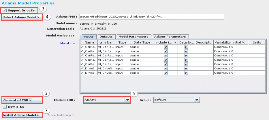
3. Make sure to select the Support DriveSim option (introduced with SimWB 2022.2).
4. Select the Adams FMU file to be imported:
a. Under the Inputs and Outputs tabs all input/output signals of the FMU are listed. They are all included by default.
b. If it is a parameterized FMU (exported using the Set Model Parameters in Adams), all parameters are listed under the Model Parameters tab. Select which parameters should be included for access in SimWB.
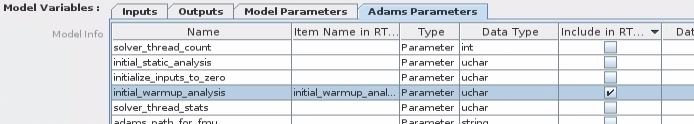
c. Under the Adams Parameters tab you can include a set of pre-defined parameters. In this guide, no parameters will be selected.
5. Select the previously created RTDB “ADAMS”.
6. Click Generate RTDB.
7. Click Install Adams Model.
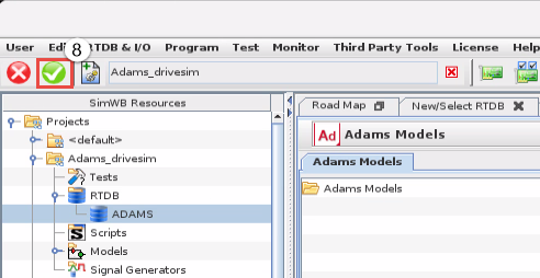
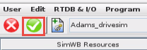
8. Click the green verify button in SimWB.
Create a Test in SimWB
To create a new Test in SimWB, follow the steps in VI-DriveSim 2023.1 documentation chapter 3.1.3, section Creating a Test with SimWB. Below are some additional notes:
1. Select Tests... from the Test menu in SimWB. Create a test called test1.
2. For a desktop simulator, add the following blocks by right-clicking in the Synchronous Models section, and select from User Models:
a. iodb_human
b. iodb_hwmap
c. iodb_udp
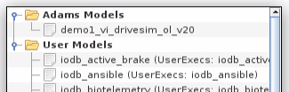
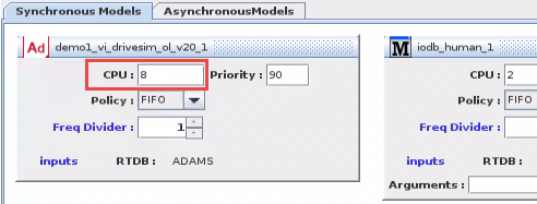
3. Add the previously imported Adams FMU model by right-clicking in the Synchronous Models section, and select the previously imported Adams FMU model demo1_vi_drivesim_ol_v20 from Adams Models.
4. For the Adams model, set CPU to be one of the cores specified in the environment variable MSC_ADAMS_THREAD_AFFINITY_SET0. For more information, refer to Adams Solver CPU affinity
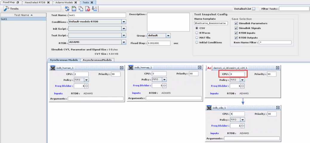
5. Make a connection between the Adams block and the iodb_udp block, by picking the Adams block and drag to the iodb_udp block.
6. For other types of simulators, other/additional blocks are required. Please consult VI-grade to set this up.
7. Don’t forget to press the green verify button in SimWB to finalize the creation of the Test:
Next time you want to create a new Test, just make a copy of this first Test and modify the new Test.
Create a Test Session in SimWB
To create a new Test Session in SimWB, follow the steps in VI-DriveSim 2023.1 documentation chapter 3.1.4, section “Creating a Test Session with SimWB”. Below are some additional notes:
1. Select Tests Sessions... from the Test menu in SimWB. Create a test called sessionA
2. Select Scheduler = Soft Real-Time
3. Set Max Overruns=1000
4. Set Max Cons. Overruns = 50
5. Environment: Select the previously created environment file “adams20234_vidrivesim” that contains all the required additional variables for Adams.
6. Init Conditions: If the Adams FMU is a parametrized FMU and parameters were selected for inclusion when importing the FMU into SimWB, select an Initial Conditions which defines the new Adams input parameter values. Not used in this example.
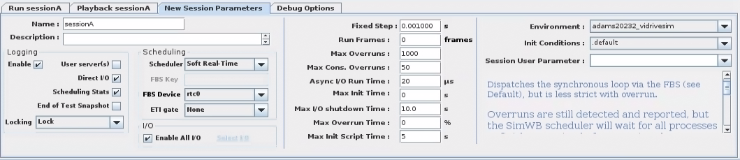
7. Don’t forget to press the green verify button in SimWB to finalize the creation of the Test Session:
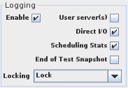
Regarding logging: Can be useful to enable Logging and Scheduling Stats to be able to plot the input/output signals of the Adams model and the frame rate of the Adams simulation, see Plot Adams model input/output signals in SimWB for details.
Start simulation in VI-DriveSim
Make sure the cores used by Adams Solver are shielded, refer to CPU shielding for details.
1. In the VI-DriveSim GUI, select Simulation  and refresh the project list
  .
.
and refresh the project list . 2. Select the previously created test.
3. Select Configuration  .
.
. 4. For a desktop simulator:
a. Select iodb_hwmap.
b. Set HWMap configuration to USB Steering Wheel (if this is a desktop simulator).
c. Save.
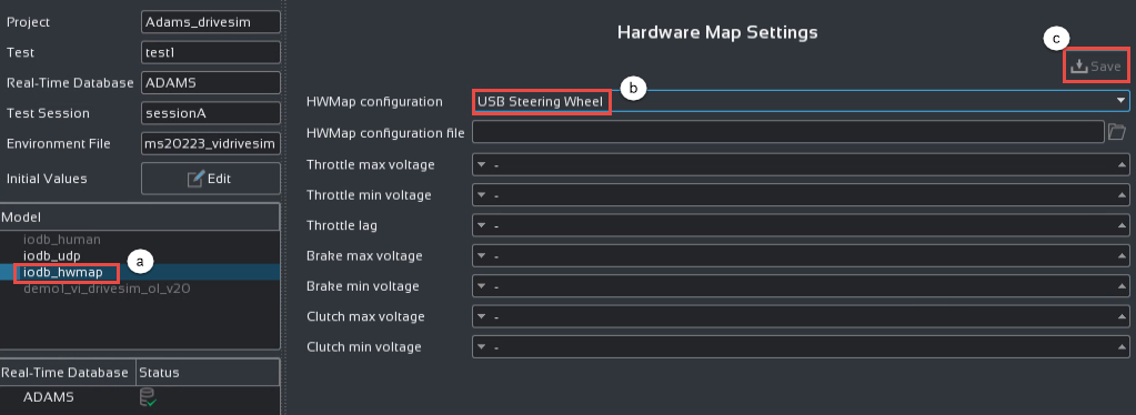
d. Under iodb_udp, make sure the Local IP address is correctly set.
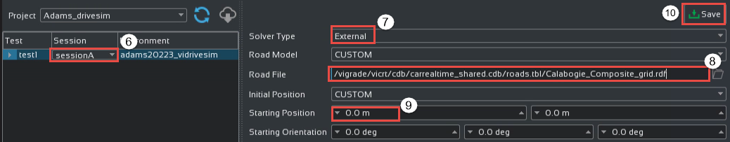
5. In the VI-DriveSim GUI, select Simulation .
. 6. Select the test test1 and test session sessionA.
7. Set Solver Type to External
8. Select a Road File.
9. Reposition the vehicle if necessary.
10. Save settings.
11. Select the visualization for track and car.
12. Start the simulation by pressing the start button  .
.
.Running STI tire models at separate cores
By default a tire model will run within the cores specified by MSC_ADAMS_THREAD_AFFINITY_SET0. Adams Solver will call the tire models and wait for the tire models to finish the force calculations.
For the tires that use the Standard Tire Interface (STI), thus the Adams Tire models and third party tire models using the STI plugin, one can specify that the tire models should use separate cores for their force calculation by setting the environment variable MSC_ADAMS_TIRE_AFFINITY. In this way, the vehicle model frame rate will not suffer from all tire force calculations. For each tire a dedicated core needs to be specified and should not interfere with the cores specified by MSC_ADAMS_THREAD_AFFINITY_SET0.
When having 4 tires, using 6 threads for the vehicle model, the specification could look like:
MDI_ADAMS_FORCE_NTHREAD=6
MSC_ADAMS_THREAD_AFFINITY_SET0=2-7
MSC_ADAMS_TIRE_AFFINITY=8,9,10,11
Running with 3rd party tire models
Cosin FTire
The implementation of the Adams Tire CTI interface has been extended by the multi-threading extension of the CTI interface as provided by Cosin. This allows you to run multiple FTire instances in parallel, one tire per core.
Pre-requisites:
■Cosin FTire installation on the Concurrent box, release 2023-3 or later. Earlier versions are not supported.
■A realtime FTire HiL license is required (provided by Cosin)
Additional variables to add to the environment file that already defines the additional variables for Adams (see Update the VI-DriveSim environment for more information):
MSC_ADAMS_TIRE_AFFINITY | Defines what cores FTire HiL should use. One core per tire. Input as a comma-separated list of integers, number of entries should match the number of tires in the model. |
COSIN_LMSERVER | Path to FTire license server or license file. |
COSIN_PREFIX | Path to FTire installation directory. |
COSIN_EXTLIB_OPENCRG | Required only if using FTire tire model and openCRG roads. Path to OpenCRG library in the FTire installation. |
Example of additional environment variables for FTire running on cores 4,5,6,7. Here, Adams Solver is assumed to run on cores 8-15, so that FTire execution does not interfere with Adams Solver.
MSC_ADAMS_TIRE_AFFINITY=4,5,6,7
COSIN_LMSERVER=/root/cosin/OLicense.olixml
COSIN_PREFIX=/home/COSIN/RedHawk7/cosin2023_3/cosin
COSIN_EXTLIB_OPENCRG=/home/COSIN/RedHawk7/cosin2023_3/cosin/extern/OpenCRG/linux64/libOpenCRG.so
Please follow the steps below to run your Adams Car vehicle model equipped with FTire HIL tires in SimWB:
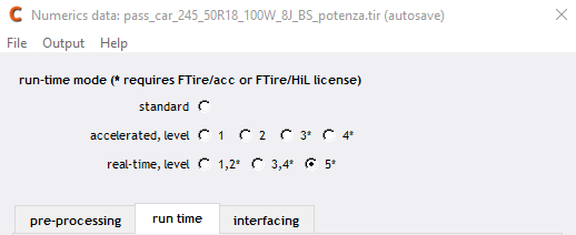
1. In order to run FTire HIL in Adams you need to have an FTire property file in which the run-time mode is set to an appropriate real time level. This can be done in cosin/tools
a. In Adams Car navigate to Simulate → Component Analysis → cosin/tools
b. Open the tire of interest and click numerics
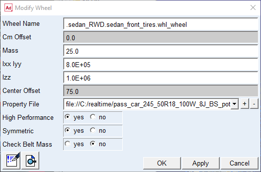
2. Ensure that your Adams Car vehicle model has the High Performance option set to yes which will activate the multi-threaded extension of the Adams CTI interface. This can be specified in the Modify Wheel dialog (right-click on a wheel in the Adams Car GUI).
3. Each FTire HIL must run on its own dedicated CPU core. This is specified using the environment variable MSC_ADAMS_TIRE_AFFINITY located in your environment file. For example MSC_ADAMS_TIRE_AFFINITY=4,5,6,7 means that core 4 is used for the 1st FTire, core 5 for the 2nd FTire, and so on.
4. Other FTire-related environment variables to be defined are:
a. COSIN_LMSERVER
b. COSIN_PREFIX
c. COSIN_EXTLIB_OPENCRG
In order to simulate FTire on a VI-Road (from VI-grade), the VI-Road property file needs to be provided through environment variable VIDRIVESIM_ROAD_PROPERTY_FILE or ADAMS_ROAD_PROPERTY_FILE. Only then .rga files are created which are read by FTire to simulate such type of roads. The .rga file contains the road_data_file reference, patch_length (default: 0.3) and number_grid_points_in_one_dir (default: 50). Default values can be overwritten by specifying environment variables MSC_ADAMS_FTIRE_PATCH_LENGTH and MSC_ADAMS_FTIRE_GRID_POINTS.
You can use environment variable VIDRIVESIM_ROAD_PROPERTY_FILE or ADAMS_ROAD_PROPERTY_FILE to change road property file without changing the Adams model files. This will allow you to quickly change road property file, for instance in Simulation Workbench.
Note that when running via VI-DriveSim GUI, the variable VIDRIVESIM_ROAD_PROPERTY_FILE will be automatically set to the road file selected from the VI-DriveSim GUI.
Note: | Both MSC_ADAMS_FTIRE_HIL_AFFINITY and MSC_ADAMS_TIRE_AFFINITY can be used to set the affinity of the CTI based tires. It is however recommended to use MSC_ADAMS_TIRE_AFFINITY as it can be used for both CTI (such as FTire) and STI (such as PAC2002) based tires. |
Note: | Using VI-DriveSim version 2022.2 you need to set environment variable LD_LIBRARY_PATH as a work around for the FTire libraries to be found. If not set, the following error occurs: "Cannot find FTire libraries". LD_LIBRARY_PATH should contain both the path to Cosin/FTire as well as VI libraries, e.g. LD_LIBRARY_PATH=/home/cosin/cosin_2023_3/cosin/lib/linux64:/vigrade/vicrt/standalone |
Siemens Simcenter Tire MF-Tyre/MF-Swift
Pre-requisites:
■Simcenter Tire MF-Tyre/MF-Swift installation on the Concurrent box, release version 2312 or later. Please read the Simcenter Tire User Guide for instructions on how to install and reference MF-Tyre/MF-Swift libraries for realtime simulation with Adams.
■Realtime tire license (provided by Siemens).
Additional variables to add to the environment file:
MSC_ADAMS_TIRE_SMP | Set to the value “USER”. This is a workaround to assure the tire model runs with SMP (parallelization). |
MDI_USER_PLUGIN_DIR | Path to MF-Tyre/MF-Swift libraries. See Simcenter Tire User Guide for details. |
MFSWIFTRT_ENTITLEMENT_FILE | Path to MF-Tyre/MF-Swift realtime license entitlement file. |
Example of additional environment variables for MF-Tyre/MF-Swift:
MSC_ADAMS_TIRE_SMP=USER
MDI_USER_PLUGIN_DIR=/opt/siemens/adams/plugin_library/linux_x86_64
MFSWIFTRT_ENTITLEMENT_FILE=/opt/siemens/mftyre_entitlement.bin
Replace paths to match your installations
For best performance, make sure you have the following settings in the tire property file:
■N_TIRE_STATES = 0
■SWITCH_INTEG = 1 (activates the internal tire solver)
Road models
Supported road formats include the following:
■Adams Tire road models
■2D road
■3D Spline road
■3D Shell road
■VI-Road
■Mesh road (triangular mesh)
■Gridmesh road
■OpenCRG
■Regular Grid Road, rgr
Note: | Some road models perform better than others, this depends on the used tire model and tire use mode. Recommendations for best performance: ■Flat roads can be used with good performance for all tire models. ■In general, grid roads perform better than triangulated mesh roads. ■VI-Road GridMesh roads perform better than VI-Road Mesh roads. ■When running with Adams Tire and belt dynamics activated, openCRG gives best performance. ■When running with FTire, rgr gives best performance. The road data file is selected via the VI-DriveSim GUI, and is stored in the environment variable VIDRIVESIM_ROAD_DATA_FILE. |
Including additional input/output signals of Adams FMU
Additional signals for the Adams model can be added in the FMU export process. These signals can be used for outputting internal states of the Adams model for plotting/debugging, connecting the Adams model to external control systems in SimWB, etc. To do so, follow the below steps.
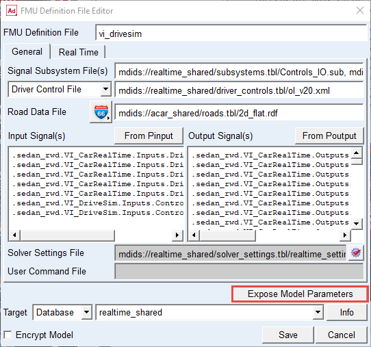
1. In Adams Car navigate to Simulate→ FMI Interface → Real Time Analysis.
2. Select the default fmd-file vi_drivesim.fmd.
3. Open the FMI Definition File Editor.
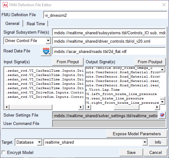
4. In this example we will add the brake line pressures from the brake system as extra output signals. Right-click in the Output Signal(s) field, select ADAMS_Variable → Browse, select:
■.sedan_rwd.brake_system_ABS_f75.left_front_brake_line_pressure
■.sedan_rwd.brake_system_ABS_f75.rear_brake_line_pressure
■.sedan_rwd.brake_system_ABS_f75.right_front_brake_line_pressure
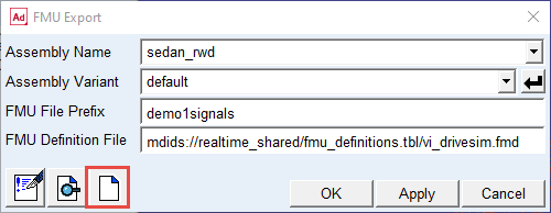
5. Change the name of FMU Definition File to vi_drivesim2.
6. Click Save. Now a new fmd-file is written, that includes the selected additional signals.
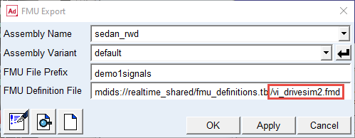
7. Click Cancel to close the editor.
8. In the FMU Export dialog box, make sure to select the newly created fmd-file vi_drivesim2.fmd and Click Ok to generate the FMU.
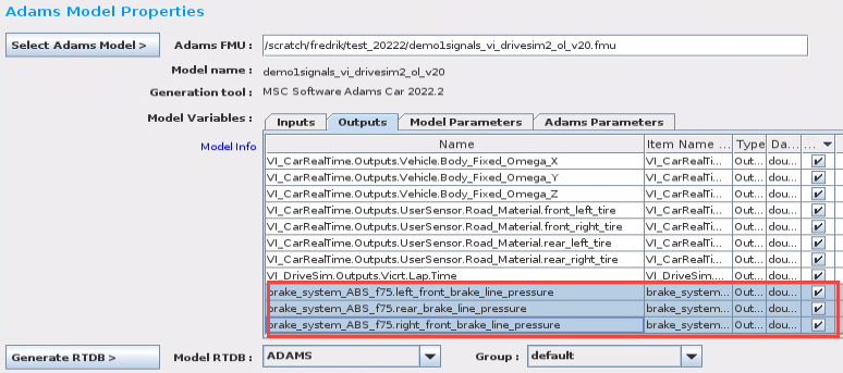
9. In SimWB, import the Adams FMU. Verify that the extra signals are there, under the Outputs tab:
10. Next, add the extra signals to the log file, so that they can be plotted after the simulation.
11. Select Analog Points in SimWB  , select the signals and Log to File:
, select the signals and Log to File: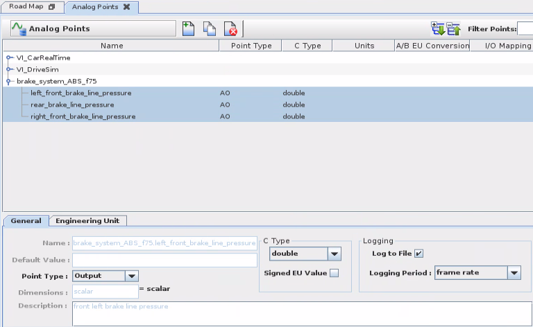
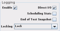
12. Create the Test and Test Session as usual, make sure to Enable Logging in the Test Session
13. Run simulation.
14. Use the SimWB Data Logger  to plot the signals.
to plot the signals.
Working with Parameterized Adams FMUs in SimWB
The FMU export in Adams supports generation of parametrized FMUs, using the “Expose Model Parameters” functionality during export. Parameters can include hardpoint locations, mass, inertia, scaling of stiffness/damping curves, use of different property files for bushings, etc.
The selected parameters can then later be modified in SimWB before starting a simulation.
When importing a parameterized Adams FMU into SimWB, make sure to include the parameters that should be available to change in SimWB. This is done under the Model parameters tab in the Adams FMU import:
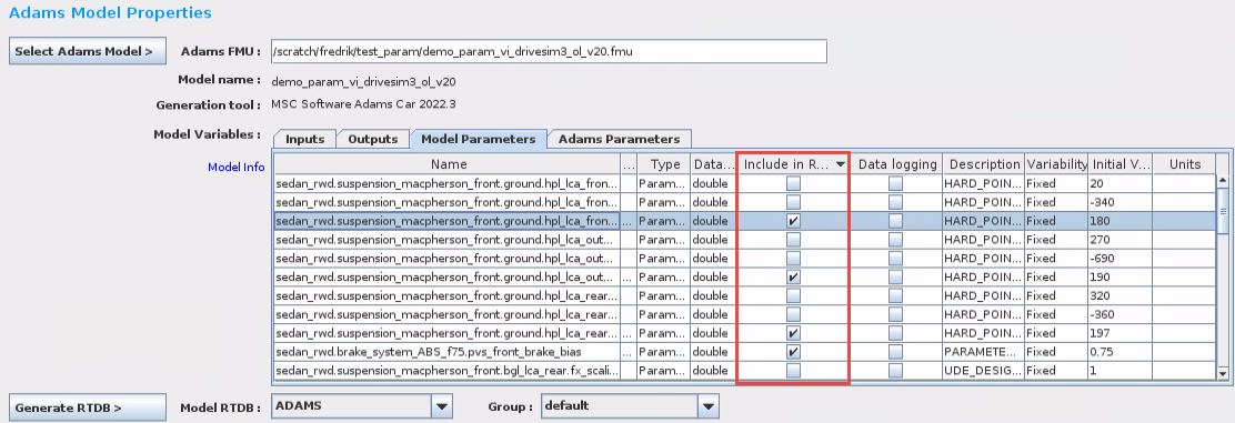
The included parameters can then be modified by creating a new Initial Conditions in SimWB. FMU parameters are in the IC found under: Initial Values → rtdb_itemsIC (and scroll to the end).
Then select the newly created Initial Conditions in the Test Session.
Optimizing the performance of the Adams simulation
CPU shielding
Before you start the simulation, it is important that the cores used by Adams Solver and the tire model are shielded. Shielding can be activated by using the “shield” command in a terminal window on the Concurrent box. Shielding will make Adams Solver run as fast as possible with minimal disturbance from other processes.
Example of how to shield cores 8-15:
■shield -m1 -a 8-15
Example of how to un-shield:
■shield -r
Example of how to check shield status:
■shield
Adams Solver CPU affinity
To get the best performance when executing Adams Solver on the Concurrent box:
■Make sure that all cores given in MSC_ADAMS_THREAD_AFFINITY_SET0 are located on the same socket. Practically this means that if you have machine with 2 processors or more, you should select cores that belong to the same processor. Using a mix of cores that belongs to different processors will degrade performance noticeably.
■On some machines there can be a difference in performance if using cores from the first or second processor. To find out how this works on your machine, run one simulation where Adams Solver uses cores from the first processor, and another simulation with cores from the second processor. If you have a 2x8 cores machine, run with MSC_ADAMS_THREAD_AFFINITY_SET0=0-7 and MSC_ADAMS_THREAD_AFFINITY_SET0=8-15 respectively. Then use the fastest option of the two tests. To check how fast Adams Solver runs, either check the frame rate of the Adams model in SimWB Real-Time Viewer, or plot the frame rate of the Adams FMU in the SimWB Data Logger. To be able to plot the frame rate you need to enable logging and include Scheduling Stats in the Test Session. For more details on how to plot the signals, refer to Plot Adams model input/output signals in SimWB.
■When defining the cores for Adams Solver, make sure to select cores that are not used by other processes of the simulator.
■Set the CPU input for the Adams model in the Test to one of the cores specified in MSC_ADAMS_THREAD_AFFINITY_SET0.
Example: If we have a 2x8 cores machine and Adams Solver should run on cores 8-15:
MSC_ADAMS_THREAD_AFFINITY_SET0=8-15
MSC_ADAMS_THREAD_AFFINITY_SET0=8-15
Initialization phase – warmup analysis
By default, a short warmup analysis is executed in the initialization phase before the realtime simulation begins. All initializations are done here and this avoids un-necessary overruns at the start of the realtime analysis. You can see that the warmup analysis has been executed by looking in the msg-file, and also from the VI-GraphSim graphics - when simulator goes into pause mode the time has progressed by a short amount:
■It is optional (but recommended) - to run the warmup analysis. It can be turned off from SimWB, if the Adams parameter initial_warmup_analysis is included when importing the Adams FMU into SimWB, and changed in Init Conditions.
■The default duration of the warmup is 0.05 sec. The length can be changed by adding the environment variable MSC_ADAMS_WARMUP_DURATION to the environment file.
■The fixed time step size in the warmup is MSC_ADAMS_WARMUP_DURATION/250. This can be overridden by adding the environment variable MSC_ADAMS_WARMUP_STEPSIZE to the environment file. The default value is 0.0002 sec (0.05/250=0.0002).
■The warmup analysis is done in two parts. The fixed time step defined above is used in the first part. In the second part the frame size (normally 0.001 sec) is used. In both parts 5 fixed iterations per time step (FIXIT=5) is used. This can be changed using the option WFIXIT/n in the MSC_ADAMS_REAL_TIME variable.
■A message file is always generated during the warmup analysis, but will be turned off by default when the realtime simulation starts.
Tips and tricks
Filtering and smoothing of Adams input signals
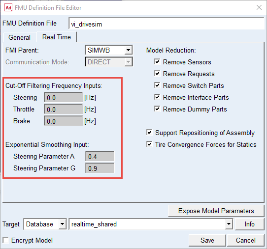
Three of the input signals of the Adams model have a built-in low-pass filter and exponential smoothing.
■Steering wheel angle (exponential smoothing first, then low-pass filter)
■Throttle (low-pass filter only, de-activated by default)
■Brake (low-pass filter only, de-activated by default)
The low-pass filter for the steering can be useful when using a gaming steering wheel, such as Fanatec, as it has a rather coarse angle resolution that can introduce noise in the steering wheel torque feedback signal.
Note: | The default value in the fmd-file provided in the <realtime_shared> database in Adams is suitable for a Fanatec steering wheel device. For an FMU to be used in a simulator with a high-end steering motor device (compact, static and DiM simulators), the filter should be disabled. |
Recommended settings:
Steering wheel device | Cut-off freq | Smoothing A | Smoothing G |
|---|---|---|---|
Fanatec (Desktop) | 80 Hz | 0.4 | 0.9 |
High-end (Compact, Static, DiM) | 0 | 0.4 | 0.9 |
Exponential smoothing:
A double exponential smoothing algorithm is used. Parameters A & G should be given in the interval [0,1]. Note that a higher value applies less smoothing: A value of 0 means maximum smoothing and 1 is no smoothing. Parameter A controls smoothing applied to the input and parameter G to an estimate related to the derivative of the input.
Set cut-off frequency and smoothing parameters in the FMU definition file (fmd) when exporting the Adams FMU:
How to update adm-file and re-run simulation
Even though the most general way of updating the Adams model is to use a parameterized FMU (refer to Working with Parameterized Adams FMUs in SimWB), it can be useful to also directly manipulate the adm-file of the Adams model. The adm-file is part of the FMU file located in: /usr/local/ccursim/projects/__project.<project_name>/ADAMS/<fmu_name>/<fmu_name>.fmu
1. On the Concurrent box, open a file browser and browse to the location of the FMU file to be modified.
2. Double-click the FMU file
3. Browse to the directory “resources”
4. Double-click the adm-file to open it in a text editor
5. Modify the adm-file, save, and exit the text editor
6. Select Update when the system asks if the FMU file should be updated
7. Run your simulation
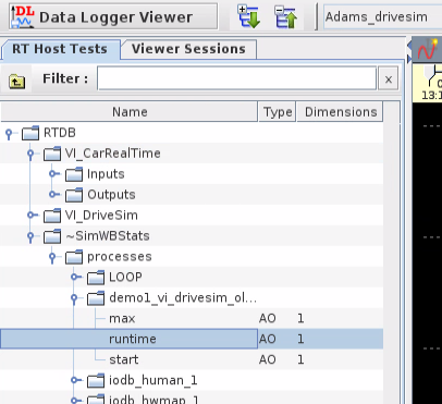
Plot Adams model input/output signals in SimWB
To plot the Adams signals after a simulation, open the Data Logger Viewer in SimWB  .
.
.Select the Test and Test Session.
Under RTDB→ VI_CarRealTime you can find all the input and output signals of the Adams model.
The frame rate of the Adams model can be found under RTDB → ~SimWBStats → processes → <fmu_name> → runtime.
Other
For a desktop simulator using a gaming steering wheel hardware, it can be useful to scale down the applied steering wheel torque because the diameter of such a steering wheel typically is less than that of a steering wheel of a real car. Do this by setting the following parameter in the environment file:
VI_DriveSim.Outputs.Cockpit.SteeringWheel.TorqueMultiplier=0.7
VI_DriveSim.Outputs.Cockpit.SteeringWheel.TorqueMultiplier=0.7
Troubleshooting: What to do if something goes wrong
This chapter lists a few strategies on how to better understand why a simulation failed.
VI-DriveSim log and SimWB log
Check the VI-DriveSim log and SimWB log for errors. Below is a list of a few errors/warnings that may appear.
DriveSim log:

SimWB log:
Exception Captured: Error in Adams(server) simulation startup.
AEI_Initialize: Error in initialization.
Using an external logger instance, taskname: demo1_vi_drivesim_ol_v20_12023/06/30 09:41:40.653493
ERROR:sched.cpp: 3846: Some models initialization failed!
The initialization of the Adams FMU failed. To further investigate what may have caused this issue, check the message file (msg) located in /usr/local/ccursim/projects/__project.Adams_drivesim/ADAMS/demo1_vi_drivesim_ol_v20/fmusources/resources/ (adapt path according to your installation, project name and FMU name)
If the message file does not contain any errors or other clues, add the MESSAGESON flag to the MSC_ADAMS_REAL_TIME variable and run another simulation.
e.g. MSC_ADAMS_REAL_TIME=ON/MESSAGESON
This will generate a full message file, including output also after the initial warm-up analysis.
Note: | Adding MESSAGESON flag is effective for debugging, but don’t forget to remove this flag when done as it is not good for solver performance |
Another thing to test is to run the acf+adm offline outside of both SimWB and VI-DriveSim, just to see how the Adams model itself runs:
■In a terminal window, change directory to /usr/local/ccursim/projects/__project.Adams_drivesim/ADAMS/demo1_vi_drivesim_ol_v20/fmusources/resources/ (adapt path according to your installation, project name and FMU name)
■Open the driver controls file (for the demo model it is the file “ol_v20.xml”) and change the abortTime parameter to, for example, 10 seconds.
■Execute Adams Car solver with the acf as input (update to your Adams installation path): > /msc/Adams/2024_1/mdi -c acar ru-solver i demo1_vi_drivesim_ol_v20.acf e.
■Check for errors in the message file.
VI-DriveSim log:

In the beginning of the simulation, VI-DriveSim calculates the norm of the accelerations of the vehicle. If the calculated value exceeds a specified limit, the simulation will be stopped.
Refer to Update initial acceleration norm limit on more information regarding modifying the limit.
Note: | The Adams FMU needs to be re-imported into SimWB and a new test created after changing this limit. |
SimWB log:
ERROR: logsend2.c: 877: Bad frame count in buffer FIFO :502 should be 2 getIdx 2 putIdx:3 getcount:3 putcount:3
Not related to the Adams model. This error means that one of the SimWB logging tasks is overruning. It can happen when it is on a CPU with one of the real-time tasks.
There are 3 logging tasks: logsend, logtxin and logtxout. Try first to assign logsend to its own shielded CPU. If that doesn't fix it then do the same for logtxin and logtxout. You can change the CPU task assignments via the 'RTDB & I/O' -> 'I/O Tasks' tab.
Another option to avoid this issue is to disable logging (done in the Test Session).
VI-DriveSim log:

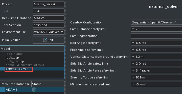
DriveSim includes the stopManager application that checks the levels of some output signals from the Adams vehicle model during the simulation. If a safety limit is reached, the simulation will abort. To modify these limits, go to Configuration in the DriveSim, select the Model as external_solver:
Required output communicators for VI-DriveSim
If you are using the templates provided with the Adams Car realtime_shared.cdb database (_VI_CarRealTime.tpl, _VI_DriveSim.tpl, _Control_States.tpl) to create an FMU of your own Adams Car model for VI-DriveSim, you need to ensure that the output communicators as listed below exist in your templates so the plant outputs (as defined in vi_drivesim.fmd) contain the correct contents for the VI-DriveSim environment.
The plant output function expressions as defined in _VI_CarRealTime.tpl and _VI_DriveSim.tpl reference to input communicators that are matched with the output communicators as shown in the table below. It should be noted that output communicators that are already part of the SDI testrig (and thus automatically included in your model) are not mentioned in the table below (e.g. .__MDI_SDI_TESTRIG.cos_std_tire_ref connected to ._VI_CarRealTime.cis_std_tire_ref).
Subsystem | Communicator matching name | Entity | Output communicator name | Example template in realtime_shared.cdb |
|---|---|---|---|---|
Front / Rear Suspension | wheel_center | location | co[lr]_wheel_center | _macpherson.tpl |
wheel_center_marker | marker | co[lr]_wheel_center_marker | _macpherson.tpl | |
suspension_upright | mount | co[lr]_suspension_upright | _macpherson.tpl | |
Steering | steering_wheel_joint | joint for motion | cos_steering_wheel_joint | _rack_pinion_steering_realtime.tpl |
steering_torque_motion | solver variable | cos_steering_torque_motion | _rack_pinion_steering_realtime.tpl | |
steering_wheel_center | location | cos_steering_wheel_center | _rack_pinion_steering_realtime.tpl | |
steering_wheel_plane | orientation | cos_steering_wheel_plane | _rack_pinion_steering_realtime.tpl | |
Engine | max_gears | parameter integer | cos_max_gears | _engine_transmission.tpl |
engine_rpm | solver variable | cos_engine_rpm | _engine_transmission.tpl | |
actual_gear | solver variable | cos_actual_gear | _engine_transmission.tpl | |
Body | body | mount | cos_body | _rigid_chassis_sedan.tpl |
seat_rail_center | location | cos_seat_rail_center | _rigid_chassis_sedan.tpl | |
Note: | ■The steering wheel plane is oriented as follows: X-axis points forward along the steering column, y-axis to the left and z-axis upwards. ■The steering wheel center is the location of the center of the steering wheel. ■The seat rail center is a point located under the driver’s seat. |
Unassigned input communicators
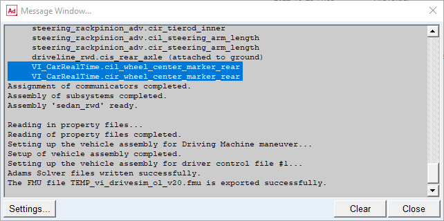
It is important that all input communicators for the three signal subsystems “Controls_IO.sub”, “VI_CarRealTime.sub” and “VI_DriveSim.sub” are correctly assigned when the FMU is generated in Adams Car. Un-assigned communicators can cause strange behavior in the simulator as the output signals may not measure the expected data. Look out for these kinds of warnings when the FMU is exported:
Known issues, general
■Two road licenses may be checked out during simulation. Please contact VI-grade for a temporary workaround.
Known issues, Adams 2024.1
■A couple of frame rate spikes can be seen at approx every two minutes from the Adams model. These are caused by the Adams licensing software.
■If using MSC_ADAMS_REAL_TIME=ON/RESULTSON to generate a results file for debugging: Res-file will be located in /usr/local/ccursim/bin.