Types of Joints
You can use several types of joints, as follows:
translational | revolute | cylindrical | spherical |
planar | fixed | inline | inplane |
orientation | parallel axes | perpendicular | convel |
hooke/universal |
Learn about Joints.
Setting the orientation of translational, revolute, cylindrical, planar, inline, inplane, orientation, and parallel axes joints.
When you select translational, revolute, cylindrical, planar, inline, inplane, orientation, or parallel axes, your template-based product displays the following option:
For the option: | Do the following: |
|---|---|
Orientation Dependency | Select one of the following: |
Setting the orientation of spherical joints
When you select spherical, your template-based product displays the following option:
For the option: | Do the following: |
|---|---|
Tips on Entering Object Names in Text Boxes. | |
Orientation | Select one of the following: ■None ■Using Two Axes |
If you set Orientation to Using Two Axes, your template-based product enables the following options: | |
I-Part Axis | Enter a Coordinate Reference to define the direction of the I-part axis, which will be from the location coordinate reference to the coordinate reference you enter in this field. |
J-Part Axis | Enter a Coordinate Reference to define the direction of the J-part axis, which will be from the location coordinate reference to the coordinate reference you enter in this field. |
Setting the orientation of perpendicular joints
When you select perpendicular, your template-based product displays the following options:
For the option: | Do the following: |
|---|---|
Tips on Entering Object Names in Text Boxes. | |
I-Part Axis | Enter a Coordinate Reference to define a location on the plane of rotation, which will be from the location coordinate reference to the coordinate reference you enter in this field. |
J-Part Axis | Enter a Coordinate Reference to define the direction of the axis of rotation, which will be from the location coordinate reference to the coordinate reference you enter in this field. |
Notes: | For the I-Part Axis, choose a Coordinate Reference that is offset from the location reference, in the plane of rotation. For the J-Part Axis, choose a Coordinate Reference that is offset from the location reference, along the rotation axis. 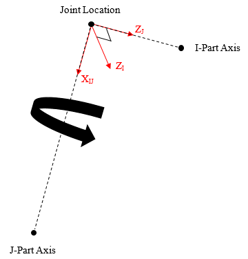 Note that the Perpendicular joint icon may not appear correctly, but the joint will constrain the proper DOF if set up correctly. |
Setting the orientation of convel, and hooke/universal joints
When you select convel, hooke, or universal your template-based product displays the following options:
For the option: | Do the following: |
|---|---|
Tips on Entering Object Names in Text Boxes. | |
I-Part Axis | Enter a Coordinate Reference to define the direction of the I-part Z-axis, which will be oriented from the location coordinate reference to the coordinate reference you enter in this field. |
J-Part Axis | Enter a Coordinate Reference to define the direction of the J-part Z-axis, which will be oriented from the location coordinate reference to the coordinate reference you enter in this field. |
Notes: | Hooke and Universal joints represent the same idealized constraint. The difference is how the axes of the joint are defined: 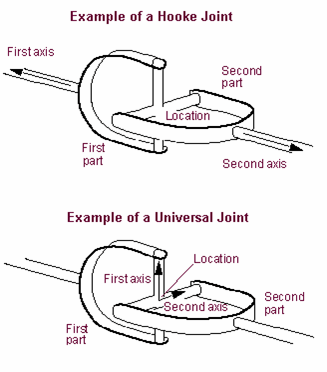 For a Hooke joint (as well as a Convel, or constant velocity joint), choose Coordinate References that are offset from the location reference, along the spin axes of the I and J parts. For a Universal joint, choose Coordinate References that are offset from the location reference, along two vectors orthogonal to the spin axes of the I and J parts. Note that the Universal joint icon may not appear as pictured above, but the joint will constrain the proper DOF if set up correctly. |