Leaf Spring Editor
Allows you to create a beam-element leaf spring model suitable for use with Adams Car. The Leaf Spring Editor uses the Makeleaf Program to create these models.
To access the Leaf Spring Editor in Adams Car:
■Create new template in Adams Car template builder then from the Build Menu, select Leaf Spring, and New.
Or
■Open an existing template or subsystem containing a leaf spring. Then from the Build menu, select Leaf Spring, and Modify.
Leaf Spring Editor has different tabs for accessing the leaf spring property file data. You can show different tabs by clicking on the tab names in the side bar on the upper left side of the Leaf Spring Editor.
For more information on different tabs of the Leaf Spring Editor, see:
Leaf Spring Editor: File Menu
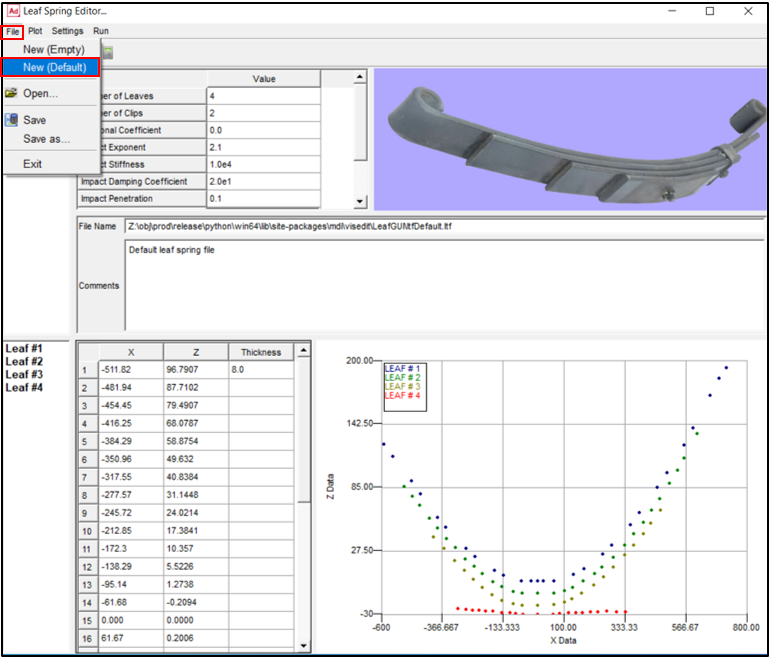
Within File Menu, you can create a new .ltf file from scratch using File → New (Empty) or with default values using File → New (Default). You can also Open a .ltf file, or save it in .ltf or .xml format. You can also close the Leaf Spring Editor using File → Exit.
Leaf Spring Editor: Plot Menu
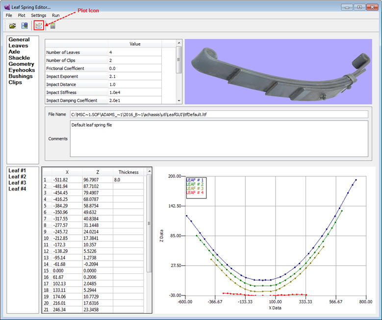
If you right-click on the plot area, using the option menu you can zoom or fit the plots. You can also set the points and curves visibilities, clear the plot or print them. Using Plot Menu or Plot icon you can re-plot the leaf profiles.
Leaf Spring Editor: Settings Menu
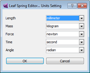
Using Settings → Units Setting menu you can change the units settings. However, note that units in the leaf template file and model units must be the same.
Leaf Spring Editor: Run Menu
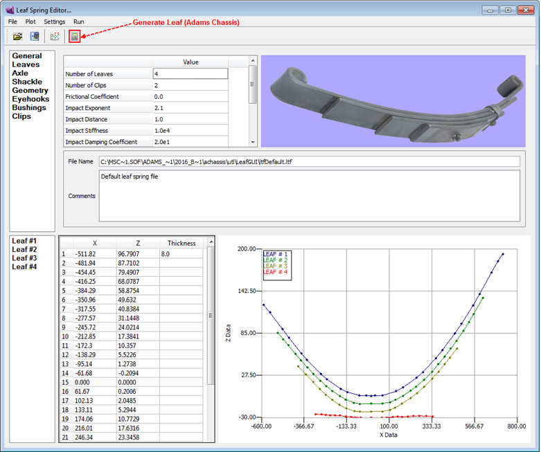
Using Run → Generate Leaf or Generate Leaf icon you can initiate generating the leaf spring process. In Adams Car, however, the process is initiated using Apply or OK button in the Create Leaf Spring dialog box.
Initiating the Generate Leaf process in Adams Car
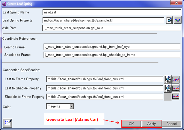
Initiating the Generate Leaf process in Adams Car
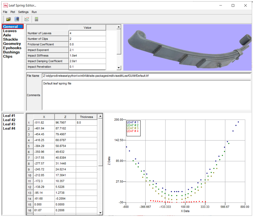
Leaf Spring Editor: General Information
This section includes parameters that are thought of as describing the entire leaf spring set; later sections take care of specific leaf/bushing properties. Here you can change the number of the leaves or clips (or the rest of parameters) by entering a new value in the cells and the corresponding tab will be updated accordingly. It is also possible to review the file name or write a comment in this tab.
For the option: | Do the following: |
|---|---|
No. of Leaves | Enter the total number of leaves in the leaf spring model. Note that if the file contains the description of more leaves than this field indicates, then only the number of leaves specified in this field will be read. This can be helpful if you want to remove the last #X leaves for experimentation. |
Number of Clips | Enter the total number of the clips. |
Frictional Coefficient | The frictional coefficient specified pertains to leaf-to-leaf friction. |
Impact Exponent | Impact exponent specifies the level of impact and is the exponent of the force characteristics. The impact with friction formulation is used. |
Impact Stiffness | Non-negative real variable that specifies the stiffness of the boundary surface interaction. |
Impact Damping Coefficient | Non-negative real variable that specifies the maximum damping coefficient. |
Impact Penetration | Positive real variable that specifies the boundary penetration at which Adams Solver (C++) applies full damping. |
Leaf Spring Mounting | This parameter indicates where the leaf spring being described will be mounted in the vehicle (this mainly influences the numbering scheme start point). Pick Rear, Front, or Other (which appears as 1, 2, or 3 in the .ltf file, respectively). Note that this is not relevant to Adams Car as the subsystem will determine the mounting location. |
Fitting Algorithm | Select second-order polynomial fitting of the leaf profile, or third-order, or fourth-order or fifth-order polynomial fit (which appears as 1 or 2 or 3 or 4 in the .ltf file, respectively). Generally, second-order is used. Choice of the best polynomial model is often a matter of trial and error, as a thumb rule count the number of inflection points then add one to select polynomial model to start with. |
Beam Formulation | Specifies the theory to be used to define the force this element will apply. By default the LINEAR theory is used (see Using the FORMULATION=LINEAR option). If the NONLINEAR option is used, the full non linear Euler-Bernoulli theory is used. If the STRING option is used, a simplified non linear theory is used. The simplified non linear theory may speed up your simulations with little performance penalties. Note: Formulation only applies to C++ Solver. |
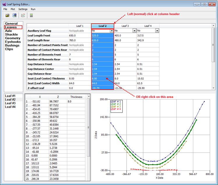
Leaf Spring Editor: Leaves
Data specific to the individual leaves are shown in this tab. For each leaf there is one column in the table. Profile data (geometry) for each leaf is entered at the bottom of the editor in a separate slide bar and table (Leaf#1, Leaf#2 and so on).
Leaf 1 is the top leaf of the main leaf stack. It has the eyehooks which are used to attach the leaves to the chassis and shackle. In general, the rest of leafpack are located below Leaf #1; the exception is for an auxiliary leaf, which is mounted on top of the leafpack and contacts the chassis. You can make any of leaves auxiliary by changing the Auxiliary Leaf Flag to Yes. Note that when you have an auxiliary leaf you also provide the contact point geometries in the Geometry tab. Therefore Auxiliary Front Contact and Auxiliary Rear Contact rows are visible only when there is a Auxiliary Leaf available in the Leaves table.
In the Leaves table, you can perform Cut, Copy, Paste operations on each leaf. The option menu can be shown by either right clicking on the "leaf column" area or left (normal) clicking on the leaf column title as illustrated in the picture. In addition, you may Delete a leaf from the table or Insert a new (empty) leaf. The Insert operation acts differently depending on if you have copied a leaf before (in this case the copied leaf will be inserted) or you have not copied a leaf (in this case a blank leaf will be copied).
Note that changing the value of Z-offset Leaf will change the offset between two leaves. Also, when copying the profile of another leaf, the Gap Distance Center and leaf Seat Thickness are added to the Z-offset value to determine the height of the leaf.
For the option: | Do the following: |
|---|---|
Auxilliary Leaf Flag | Indicates whether the leaf being defined is an auxiliary leaf (1) or not (0). An auxiliary leaf is located on top of the leafpack and, after the leaf spring has been compressed to a point, the auxiliary leaf contacts the chassis and augments the spring pack. This flag is not available for Leaf 1, since Leaf 1 is always the leaf with eyehooks. In fact, the auxiliary leaf should generally be the last leaf specified. You need to create "Auxiliary Front Contact" and "Auxiliary Rear Contact" hard points in *.ltf file under "Geometry" section. |
Leaf Length Front/Rear | Enter the arc length of the front and rear sections of the leaf being defined in mm, respectively, from the X=0.0 point defined in the profile. |
Number of Contact Points Front/Rear | Number of Rear Contact Points (<= # of elements*2). These integer numbers define the number of CONTACT POINTS to be created for the front and rear, respectively, for this leaf and the leaf directly above it. These contacts are used to keep the leaves from passing through each other as they deflect, in effect modeling the physical contact of the top of the current leaf with the bottom surface of the leaf above it. A maximum of two contact points per beam element is allowed (the number of beams used is defined by the number of elements specified in the next rows of the table). Therefore number of contact points should be equal or less than number of elements multiply by two. |
Number of elements per Front/Rear Leaf | The leaf being defined will be broken up into discrete sections, each of which will be modeled using an Adams beam element. These two parameters define how many beam elements should be used in discretizing the front and rear sections of the leaf, respectively. A maximum of 45 elements per half-leaf has been imposed for memory allocation purposes. |
Displacement to Contact Bumper Front/Rear | Enter the distance along the leaf to position the bumper contact. Only one bumper per half leaf is allowed. Active if value is positive. Bumper is optional entity in leafspring |
Contact Bumper Height Front/Rear | Enter the height of the bumper contact. Only one bumper per half leaf is allowed. Active if value is positive. |
Gap Distance Front/Center/Rear | These values define the gap between this leaf and the leaf above it, in mm. They are always defined as a positive number. Center gap distance is used to determine the location of the leaf-to-leaf bushings. The front and rear gap is used to determine the location of the contact forces. If you are copying profile to another leaf (Leaf Profile to Copy=1 in *.ltf file) then gap distance will be added to the Z offset and seat thickness values to determine Z offset. |
Seat (Leaf Center) Thickness | This parameter defines the thickness (Z-direction) of the leaf being defined at the X=0.0 point in mm. Be careful about conflicts when assigning the Seat Thickness and the THICKNESS column in the profile. If the tabular value at X=0.0 does not match the given Seat Thickness value, then the Seat Thickness value will be used at X=0.0. A warning message will be issued to this effect. (If you want to let the tabular thickness value at X=0.0 take precedent, enter 0.0 for the Seat Thickness value.) |
Seat (Leaf Center) Width | Defines the width (Y-direction) of the leaf being defined at the X=0.0 point. |
Z-offset Leaf | Z-offset for leaf profile. This value is ADDED to the Z-values of the entire profile given for this leaf. This value is especially important if another leaf profile is being copied; the offset can be used to place it in the correct position. Note: The gap distance center and leaf Seat Thickness only are used to determine the height of the leaf when copying the profile of another leaf. |
Material Properties: E-Modulus | Defines Young's modulus of elasticity for the material from which the leaf being defined is constructed. This value will be used in defining the BEAM statements for the Adams representation. |
Material Properties: G-Modulus | Defines the shear modulus of elasticity for the material from which the leaf being defined is constructed. This value will be used in defining the BEAM statements for the Adams representation. |
Material Properties: Density | Defines the density of the material (kg/mm**3) from which the leaf being defined is constructed. This value will be used in defining the BEAM statements for the Adams representation. |
Material Properties: Damping Ratio | Specifies the ratio for calculating the structural damping matrix for the beam. Adams Solver multiplies the stiffness matrix by this value to obtain the damping matrix. |
ASY ASZ | Specifies the correction factor for shear deflection in the Y (ASY) and Z (ASZ) directions, according to Timoshenko beam theory. These factors are used to define the BEAM elements for the current leaf. |
Fitting Points | Select if every point is to be used for fitting ("1" in .ltf file) or if first and last points are the bushing points ("0" in .ltf file). This option is available only for the first leaf. If "Exclude first/last points" is chosen, the first and last points given in the profile will be used as the bushing points and will not be used in the polynomial fitting process. If "Every point" is selected, then all points will be considered during the fitting points. In this case, the shackle bushing point is to be estimated. |
Leaf Profile and Thickness | This section is used to define the profile of the leaf and its thickness in free condition. The X column defines the position along the arc length of the spring. The Z values define the curvature of the top of the spring at the points on the spring which correspond to X. (This convention is used because it is typically the way data is available.) There must be a corresponding Z value for each X value entered. Refer to below image. The Thickness column defines the thickness of the leaf at each X value. This column is flexible about the amount of data entered. Data may be defined only at desired points, or at all points. The only restriction is that at least ONE value must be entered. The data are processed in the following manner: ■Empty points between defined points are linearly interpolated ■Empty points at the ends of the spring (outside of defined points) will be held constant at the last defined value Thus, it is possible to define a constant thickness spring by entering only one value; further, this value can be defined at any X value. A "tapered" leaf, as used in early versions of the code, can be defined by entering only the center and end-point thickness values. Or, the whole leaf thickness value may be entered if they form a more complex geometry. Note: The X-value at the center of the leaf defined in the profile must be 0.0; this position is also referred to as the seat of the leaf. Also, since the coordinate system for Adams models has X positive pointing rearward with respect to the vehicle, the leaf spring data must have X positive pointing rearward and, of course, X negative point forward. So the front leaf must be in negative X-axis 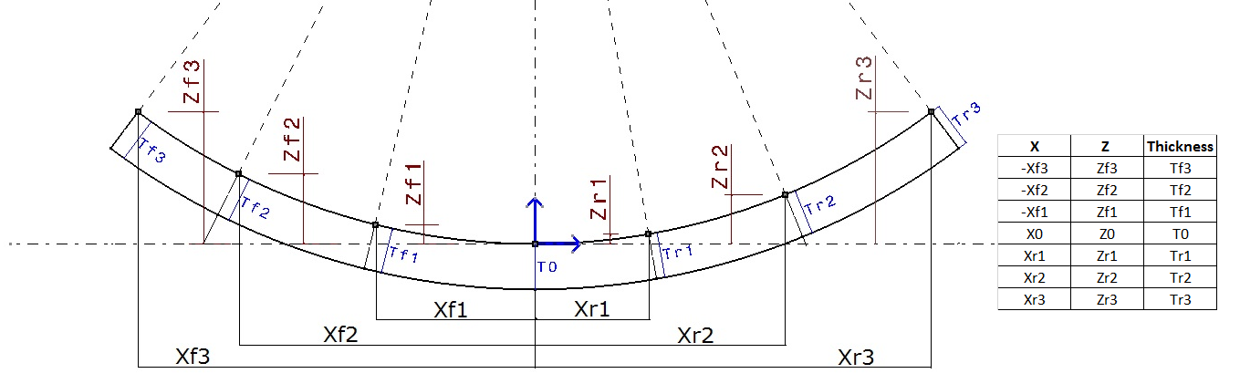 |
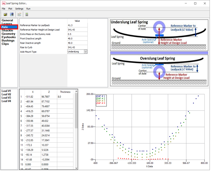
Leaf Spring Editor: Axle Information
This tab contains information pertaining to the axle/housing that is to be connected to the spring pack.
For the option: | Do the following: |
|---|---|
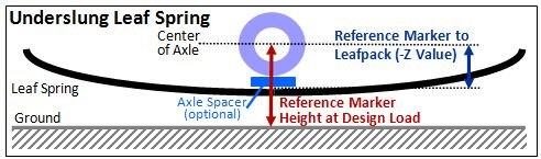
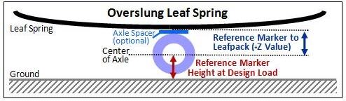
Reference Marker to Leafpack | This value is the Z-height of the reference marker for the axle with respect to the coordinate system used to define the leaf profile(s). This is the vertical distance between reference marker (center of Axle) and leafpack surface (bottom of an overslung leaf or the top of the underslung leaf). This value is absolute for Underslung Leaf Spring and Overslung Leaf Spring. |
Reference Marker Height at Design Load | The Z-height (mm) of the reference marker is used to stop the simulation when the leaf spring is exercised from rise-to-curb position to design position. Once the axle reaches this point, the spring is assumed to be at design-load conditions and the simulation will be halted (see rise-to-curb below). This value is absolute Z-height of reference marker in design load condition. |
Extra Mass on the Dummy Axle | Specify the mass estimate (kg) of the unaccounted-for hardware used to assemble the spring pack and connect it to the axle (U-bolts, spacers, and so on.). |
Front/Rear Inactive Length | The front and rear inactive lengths (mm) are the lengths of the leaf spring, which are regarded as "rigid" near the X=0.0 point. |
Rise-to-Curb | The Z-height (mm) of the reference marker is used to stop the simulation when the leaf spring is exercised from free position to rise-to-curb position. This value is absolute Z-height of reference marker in rise-to-curb condition Rise to curb can be used to specify the rise to installation position. During the makeleaf process, the leaf will be exercised to the rise-to-curb value. At this value the leaf to frame (front eye), leaf to shackle (rear eye) and shackle to frame bushings will be reset such that the preload on these bushings are zero. The leaf will then be continued to be exercised from the rise-to-curb position to design position. The preload on the bushing at the design position will be the load generated by exercising the leaf from rise-to-curb to design height. |
Axle Mount Type | Specifies whether the leaf spring pack is mounted above (Overslung) or below (Underslung) the axle. |
Note: | The ground height may or may not correspond to the bottom of the tire. This will depend on the design layout of your vehicle. |
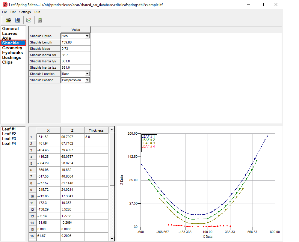
Leaf Spring Editor: Shackle Information
This tab contains information describing the leaf spring shackle.
For the option: | Do the following: |
|---|---|
Shackle Option | Select Yes or No. Select “Yes” to include shackle part in the leafspring, otherwise select “No” to exclude shackle part from the leafspring. |
If you set Shackle Option to Yes, the Leaf spring editor enables the following options: | |
Shackle Length | Enter the physical length (mm) of the shackle part, from eye center to eye center. |
Shackle Mass (kg) | Specify the mass (kg) of the leaf spring shackle. |
Shackle Inertia | Specify the inertial properties Ixx, Iyy, Izz (kg*mm**2) of the leaf spring shackle when it is laid in flat position. X-dir is its pointing direction. |
Shackle Location | Select Front or Rear to specify whether the shackle is at the front or rear of the leaf spring pack. |
Shackle Position | Indicates whether the shackle is used in tension or compression. Select one: ■Compression (above leaf) - when the leaf eye is below the shackle-to-body point, the link is in compression. ■Tension (below leaf) - when the leaf eye is above the shackle-to-body point, the link is in tension. |
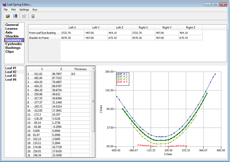
Leaf Spring Editor: Geometry
In Adams Car, this tab is inactive (grayed out) as the geometry values are specified in the New Leaf Spring dialog box and therefore hardpoint data is automatically populated from subsystem file.
These points indicate where in space the leaf springs will be constructed. Enter the X, Y, and Z positions for both the front and rear chassis connection points. This must be done for both left and right springs.
For the option: | Do the following: |
|---|---|
Front Leaf Eye Bushing | Corresponds to points 1 and 2 in the suspension subsystem file. |
Shackle to Frame | Corresponds to points 20 and 21 in the suspension subsystem file. |
Another entry for the chassis contact points is necessary if an auxilliary leaf spring is defined in the template.
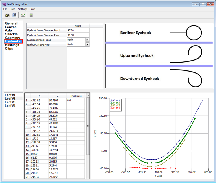
Leaf Spring Editor: Leaf Eyehook Information
For the option: | Do the following: |
|---|---|
Eyehook Inner Diameter Front/Rear | Enter the diameter of the inside of the eyehook. |
Eyehook Shape Front/Rear | Select one: 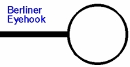  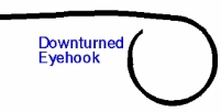 |
Leaf Spring Editor: Bushing Information
This tab is used to define the properties of the bushings in the model. In Adams Car the leaf spring bushings will be defined in their respective interfaces and this tab will only display the interleaf bushing data.
It is also possible to launch the editor in "standalone" mode. Since the bushing data is not available, all bushing data can be modified in the editor. Note that for this case, only linear bushing rates are supported.
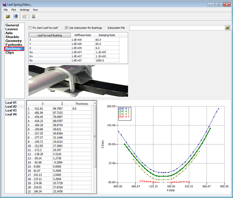
Leaf Spring Editor (launched from Adams Verticals)
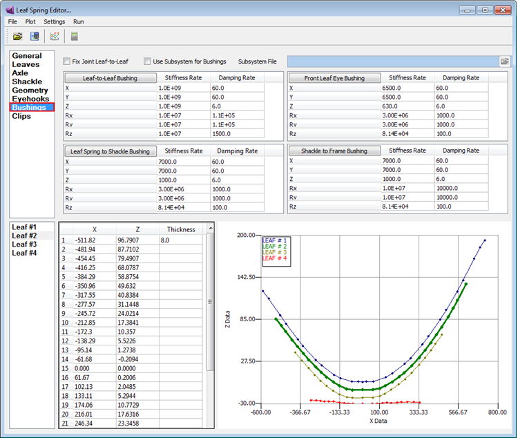
Leaf Spring Editor (standalone)
For the option: | Do the following: |
|---|---|
Leaf-to-Leaf Bushing | Specify the translational and rotational spring and damping rates for the lumped parameter describing the connection of the leaves to each other at the X=0.0 point. These bushings are used to keep the leaves from moving laterally or twisting from each other. They should have rather large values (~1.0E+09 for translational rates and ~1.0E+07 for rotational rates). |
Front Leaf Eye Bushing | Specify the translational and rotational spring rates for the bushing at the front of the leaf. |
Leaf Spring to Shackle Bushing | Specify the translational and rotational spring rates for the bushing at the rear of the leaf. |
Shackle to Frame | Specify the translational and rotational spring and damping rates for the bushing at the point where the shackle connects to the chassis. |
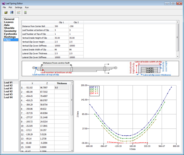
Leaf Spring Editor: Leaf Clips
Leaf clips bind together the first stage leaves on a leaf spring suspension. They are intended to prevent any separation of the leaves in the vertical and lateral direction, with little or no effect on longitudinal movement. They can be installed in front, behind or both front and behind the wheel center.
These are optional attachments at the ends of the leaf spring and if there is no clip defined in the property file, the clip table will be empty. You can add clips to the leaf spring by increasing the number of the clips in the General tab.
Similar to Leaves tab, Cut, Copy, Paste, Insert, and Delete operations are possible in the Clips tab by accessing the option menu (right click in column area or left click on title area).
Example
Feature Number | Clip Number |
|---|---|
1 | Distance from center bolt |
2 | Leaf number at bottom of clip |
3 | Leaf number at top of clip |
4 | Vertical inside height of clip |
5 | Vertical clip cover height |
7 | Lateral inside width of clip |
8 | Lateral clip cover thickness |
Leaf Spring Editor: Command Shell
If you want to run the Makeleaf without running the Leaf Spring Editor you can use the command shell. Also, you can modify the options of the Leaf Spring Editor using the command shell, for example, by default, Adams Car creates a rear leaf spring and you can change this in the command shell. Learn how to use the Leaf Spring Editor.
Changing options using the command shell
For the option: | Do the following: |
|---|---|
Front leafspring | Use the -f option. For example, adams* -makeleaf -f sample_front.ltf |
Bushings | You have the option of using all standard Adams Car bushing types. Use the -b option. Specify either a front or rear Adams Car datafile. For example: adams* -makeleaf -b test_rst.xml sample_rear.ltf adams* -makeleaf -f -b test_fst.xml sample_front.ltf |
Keep Bushings | By default, the leaf eye and shackle bushings will not be included in the leaf model file. To change this, use the -k option. For example: adams* -makeleaf -b test_rst.xml -k sample_rear.ltf Bushing information will remain in sample_rear.py, Adams Car will not write the bushings when the Adams Car model is created with this leaf. Note: In almost every case, you will not need to keep the bushings in the leaf model file. This way, Adams Car will always generate the bushings when creating the full-vehicle or exerciser model. If the bushings change independent of the rest of the leaf spring, makeleaf doesn't have to be run again. This also aids Design of Experiment (DOE) analysis. Please note that bushings are always included in the leaf model when the leaf is exercised to the design position during the makeleaf program. |
Help | A help option is available from the command line with makeleaf: adams* -makeleaf -h Note: * is for Adams version. |
Beam Element Leaf Spring Modeling
Leaf spring data is stored in Leafspring Template File (.ltf) which would be the input to Makeleaf program. Makeleaf creates a leafspring model which composed of a series of parts connected via beam elements. The contact between the leaves is modeled using vector forces and the impact function. You need to enter input data for the leaf spring in its unloaded or free-free configuration.
Beam Element Leaf Spring Model Flowchart
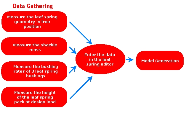
You would need the information below, at minimum, for creating a leafspring in Adams.
■Each leaf information
■X-Z data of each leaf (Leaf profile in free-free condition)
■Physical (arc) length of each leaf
■Density, E modulus, G modulus, damping ratio, etc
■Leaf thickness
■Shackle information
■Shackle location
■Mass, length, inertia, etc
■Bushing rates for
■Leaf to frame bushing
■Leaf to shackle bushing
■Shackle to frame bushing
■Location of leaf to frame and shackle to frame bushings
■Axle Information
■Axle type (Underslung or Overslung)
■Height of leaf spring pack at rise to curb and design loaded condition
■Reference marker to leafpack which is a distance between axle center to leafseat surface
■Eyehook type (Berliner, upturned, downturned)
■Clips information
Leaf Spring in Adams Car
Adams Car supports the direct modeling of leaf springs.
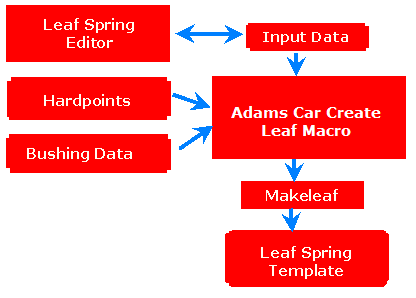
The Leaf Spring Editor is used to input data such as shackle information, axle information, leaf profiles, clip information, eyehook types along with hardpoints and bushing data.
It is used either for creating a new .ltf file or for modifying an existing .ltf file.
In Adams Car, bushing and hardpoint data from the template is provided in the leaf spring create/modify dialog box and is taken for leafspring generation.
The Adams Car leafspring create macro uses the .ltf file, along with bushing and hardpoint data from the template to create a subsystem file which is the input for the Makeleaf program.
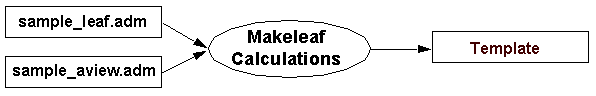
The Makeleaf Program generates a leafspring model dataset file (*.adm) which gets merged with the Adams Car template. This template can be used for creating a subsystem file in Adams Car for further analysis.
Generated leafspring in Adams Car has asymmetric bushing to match the bushing orientations of leafspring model generated from makeleaf programe.
Makeleaf Program
Makeleaf is a program that builds a beam-element leafspring model suitable for use with Adams.
Makeleaf takes the leaf data in the leaf spring template file (.ltf), and creates both Adams dataset model files (.adm) and a beam-element leaf spring property file (.py).
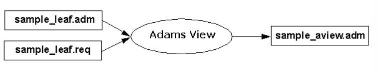
If the leaf spring template file is called sample.ltf, Makeleaf creates Adams dataset model files (sample_aview.adm, sample_leaf.adm and sample_reset.adm) and sample.py.
Note that in the case of Adams Car, the calculations are performed within the macro and the end result is a template rather than a python file. View An Example Leaf template File.
Using Makeleaf
You can run Makeleaf from the Leaf Spring Editor or the command shell.
To run Makeleaf from the Adams interface:
In Adams Car:
■In Template Builder mode, from the Build menu, select Leaf Spring, and New.
Note: | You can switch between Standard Interface and Template Builder by pressing F9 key. Also, the Build menu is only active when there is a template model present in the Adams Car Template Builder session |
Learn more about the Leaf Spring Editor.
To run Makeleaf from the command shell:
1. Create the leaf template file.
2. In the command shell, enter: mdi -makeleaf sample_rear.ltf
This produces sample_rear.py and sample_aview.adm, sample_leaf.adm and sample_reset.adm.
See Leaf Spring Editor: Command Shell to learn more about using the command shell to change leaf spring options.
How Makeleaf Works
Makeleaf builds the leaf .py file through a series of steps. During these steps, some auxiliary files will be created.
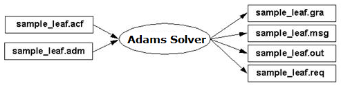
Makeleaf script first builds a leaf spring in its free state. Based on the leaf spring property file (.ltf), an Adams dataset model file (*.adm) and Adams control file (*.acf) are created in undeformed position. These are saved as sample_leaf.acf and sample_leaf.adm.n
3. The Adams control file (*sample_leaf.acf) created in the previous step is run with Adams Solver to exercise the leaf spring from the "free" position to the "rise to curb" position given in *.ltf file. This position is represented in the model as SENSOR/4, and Adams Solver will stop the simulation when the axle reaches this position.
This is the first quasi-static analysis. The model is imported in Adams View, the results from the previous step are read, and a new model file at rise-to-curb condition is written and saved in sample_aview.adm.
4. Then Makeleaf executes the "reset_bushings" python script, which takes the model (sample_aview.adm) and removes bushing preloads by resetting marker positions. The updated model is saved in sample_reset.adm and sample_reset.acf files.
5. Adams View is executed and exercises the leaf spring from rise-to-curb to design position as given in *.ltf files to create an Adams dataset model file of the leafspring in the design position. This position is represented in the model as SENSOR/1 to 3, and Adams Solver will stop the simulation when the axle reaches this position. This is the second quasi-static analysis, and the model is saved as sample_aview.adm which overwrites the sample_aview.adm file generated after the first quasi-static analysis.
6. Note that in the case of Adams Car, the calculations are performed within the macro and the end result is a template or subsystem rather than a python file.
During this process, files such as sample_leaf.adm, sample_aview.adm etc are generated in your working directory in the folder named sampleBuildFiles. This folder will be automatically deleted after closing your Adams session. If you want to keep these files on your disk then you need to set the following environment variable.
Set ACAR_DEBUGGING to "1" to avoid removal of files from your working directory.
Adams Car:
Using Leaf Springs
To use a leaf spring in your Adams Car model, see Leaf Springs in the working with components section.
Static Solver Funnel for .acf files
The static solver funnel option is a tool to help analysts achieve convergence with their Adams models that contain beam element leaf springs or other large modeling elements. The funnel gradually tightens error, imbalance, and stability tolerances after achieving static equilibrium.
The static funnel option is activated if the funnel parameter in the System File is set to 1: system_parameters → solver → static → funnel_flag
The following lines of code appear in the .acf files for Full-Vehicle models:
! Static Funnel:
equil/maxit=50.00, err=10000, imb=10000, stab=10000
con/fun=user(1010,555)
equil/maxit=50.00, err=100, imb=100, stab=10
con/fun=user(1010,555)
equil/maxit=50.00, err=0.1, imb=0.1, stab=0.1
con/fun=user(1010,555)
equil/maxit=50.00, err=0.001, imb=0.10000, stab=0.01
After each equil/maxit statement, the equilibrium CONSUB (con/fun=user(1010)) is invoked.
The following lines of codes appear in the acf files for Half-Vehicle models:
! Static Funnel:
equil/maxit=50.00, err=10000, imb=10000, stab=10000
sim/stat
equil/maxit=50.00, err=100, imb=100, stab=10
sim/stat
equil/maxit=50.00, err=0.1, imb=0.1, stab=0.1
sim/stat
equil/maxit=50.00, err=0.001, imb=0.10000, stab=0.01
The values for the last equil/maxit statement are defined by the user in the system parameters. The maximum number of iterations is always taken from the system parameters.
An Example Leaf template File
================================================================================
LEAF_SPRING_TEMPLATE_NEW TEMPLATE FOR THE LEAF SPRING EDITOR
--------------------------------------------------------------------------------
(Note: All input information must be in Left-Justified format.)
================================================================================
TITLE
--------------------------------------------------------------------------------
Default leaf spring file
================================================================================
GENERAL INFORMATION
--------------------------------------------------------------------------------
4 = No. of Leaves
0.0 = Frictional Coefficient
2.1 = Impact Exponent
1 = Leaf Spring ID Number (pick 1-REAR, 2-FRONT, 3-OTHER )
1 = Flag for fitting algorithm (1-2nd poly, 2-3rd poly)
1 = Flag for contact algorithm (1-impact w/frict)
SUSPENSION BRACKET ATTACHMENT POINT (ADAMS Coordinate)
--------------------------------------------------------------------------------
POINT LOCATIONS
LEFT (mm) RIGHT (mm)
GEOMETRY HARDPOINT X Y Z X Y Z
------------------------------ ------------------------ ------------------------
Front Leaf Eye Bushing 1-2 3722.70 -497.06 404.10 3722.70 497.06 404.10
Shackle to Frame 20-21 5070.30 -497.06 675.43 5070.30 497.06 675.43
AXLE INFORMATION
--------------------------------------------------------------------------------
0.5 = Extra Mass on the Dummy Axle (U-bolts, spacers, etc.)
41.3 = Reference Marker to Leafpack (bot-OVERSLUG, top-UNDERSLUG)
40.0 = Front Inactive Length (mm)
40.0 = Rear Inactive Length (mm)
541.43 = Reference Marker Height at Design Load
UNDERSLUNG = Axle Mount Type (UNDERSLUG OR OVERSLUG)
541.43 = Rise to Curb (mm)
SHACKLE INFORMATION
--------------------------------------------------------------------------------
139.88 = Shackle Length
0.73 = Shackle Mass (kg)
3.67E1 = Shackle Inertia: Ixx (kg*mm**2) (when it's laid in flat pos.)
8.81E2 = Shackle Inertia: Iyy (kg*mm**2) (x-dir. is its pointing dir.)
8.81E2 = Shackle Inertia: Izz (kg*mm**2)
REAR = Shackle Location (FRONT or REAR)
COMPRESSION = Shackle Position (COMPRESSION(above leaf) or TENSION(below leaf))
LEAF EYEHOOK INFORMATION
--------------------------------------------------------------------------------
47.30 = Front Eyehook Inner Diameter (mm)
31.35 = Rear Eyehook Inner Diameter (mm)
BERLIN = Front Eyehook Shape (BERLIN, UPTURNED, OR DOWNTURNED)
BERLIN = Rear Eyehook Shape (BERLIN, UPTURNED, OR DOWNTURNED)
CLIP INFORMATION
--------------------------------------------------------------------------------
2 = No. of clips
CLIP 1
350 = Distance from center bolt (+ve fore)
3 = Leaf Number at bottom of clip
1 = Leaf Number at top of clip
35.00 = Vertical inside height of clip
2.5 = Vertical clip cover height
10000 = Vertical clip cover stiffness
86 = Lateral inside width of clip
2.5 = Lateral clip cover thickness
10000 = Lateral clip cover stiffness
--------------------------------------------------------------------------------
CLIP 2
-350 = Distance from center bolt (+ve fore)
3 = Leaf Number at bottom of clip
1 = Leaf Number at top of clip
35.00 = Vertical inside height of clip
2.5 = Vertical clip cover height
10000 = Vertical clip cover stiffness
86 = Lateral inside width of clip
2.5 = Lateral clip cover thickness
10000 = Lateral clip cover stiffness
BUSHING INFORMATION
Subsystem File =
--------------------------------------------------------------------------------
SPRING RATES (TRANSLATIONAL AND ROTATIONAL)
RATE (N/mm) RATE (N-mm/rad)
RADIAL RADIAL AXIAL CONICAL CONICAL TORSIONAL
BUSHINGS (RATES) PT (X) (Y) (Z) (X) (Y) (Z)
---------------------------- -------------------------------- --------------------------------
Front Leaf Eye Bushing 1-2 6500.0 6500.0 630.0 3.00E+06 3.00E+06 8.14E+04
Leaf Spring to Shackle 7-8 7000.0 7000.0 1000.0 3.00E+06 3.00E+06 8.14E+04
Shackle to Frame 20-21 7000.0 7000.0 1000.0 1.0E+07 1.0E+07 8.14E+04
Leaf-to-Leaf Bushing 1-1 1.0E+09 1.0E+09 1.0E+09 1.0E+07 1.0E+07 1.0E+07
DAMPING RATES (TRANSLATIONAL AND ROTATIONAL)
DAMPING (N-s/mm) DAMPING (N-s/rad)
RADIAL RADIAL AXIAL CONICAL CONICAL TORSIONAL
BUSHINGS (DAMPING) PT (X) (Y) (Z) (X) (Y) (Z)
---------------------------- -------------------------------- --------------------------------
Front Leaf Eye Bushing 1-2 60.0 60.0 6.0 1000.0 1000.0 100.0
Leaf Spring to Shackle 7-8 60.0 60.0 6.0 1000.0 1000.0 100.0
Shackle to Frame 20-21 60.0 60.0 6.0 10000.0 10000.0 100.0
Leaf-to-Leaf Bushing 1-1 60.0 60.0 6.0 1.1E+05 1.1E+05 1500.0
================================================================================
LEAF # 1
--------------------------------------------------------------------------------
650.0 = Front Leaf Length (mm)
785.0 = Rear Leaf Length (mm)
7 = No. of Elements per Front Leaf (<= 45)
8 = No. of Elements per Rear Leaf (<= 45)
8.00 = Seat (Leaf Center) Thickness (mm)
64.0 = Seat (Leaf Center) Width (mm)
2.00E5 = Material Properties: Emod
7.9E4 = Material Properties: Gmod
7.86E-6 = Material Properties: Density (kg/mm**3)
0.1 = Material Properties: Damping
1.2 = ASY
1.2 = ASZ
1 = 1, if every point is to be used for fitting,
0, if First and Last points are the bushing points
(If " 1 " is chosen, the shackle bushing point is to be estimated.)
0.0 = Z-offset leaf
X Z Thickness
----------- ----------- -----------
-589.92 123.77 8.0
-555.09 113.34
-486.13 90.56
-451.50 79.13
-383.58 57.89
-352.91 49.03
-276.92 29.85
-242.13 22.37
-167.64 9.57
-131.96 5.11
-65.21 0.51
-27.11 0.19
0.00 0.00
21.05 0.17
61.97 0.46
136.52 6.21
175.23 11.56
248.37 24.64
283.46 32.38
353.76 51.22
388.92 61.91
457.23 84.66
494.53 97.99
558.79 123.50
593.31 138.57
658.94 168.07
694.25 183.73
720.80 193.30
(Note: The X value at the Center LEAF must be 0.0)
(Note: The Front LEAF must be in negative X-axis.)
================================================================================
LEAF # 2
--------------------------------------------------------------------------------
0 = Auxiliary Leaf Flag
2 = No. of Front Contact Points ( <= # of elements*2 )
2 = No. of Rear Contact Points ( <= # of elements*2 )
2.54 = Center Gap Distance between Leaf #1 And #2 (liner thick.) (mm)
2.54 = Front Gap Distance between Leaf #1 And #2 (liner thick.) (mm)
2.54 = Rear Gap Distance between Leaf #1 And #2 (liner thick.) (mm)
525.0 = Front Leaf Length (mm)
635.0 = Rear Leaf Length (mm)
5 = No. of Elements per Front Leaf (<= 45)
6 = No. of Elements per Rear Leaf (<= 45)
8.00 = Seat (Leaf Center) Thickness (mm)
64.0 = Seat (Leaf Center) Width (mm)
2.00E5 = Material Properties: Emod
7.9E4 = Material Properties: Gmod
7.86E-6 = Material Properties: Density (kg/mm**3)
0.1 = Material Properties: Damping
1.2 = ASY
1.2 = ASZ
-10.74 = Z-offset leaf
X Z Thickness
----------- ----------- -----------
-511.82 96.7907 8.0
-481.94 87.7102
-454.45 79.4907
-416.25 68.0787
-384.29 58.8754
-350.96 49.632
-317.55 40.8384
-277.57 31.1448
-245.72 24.0214
-212.85 17.3841
-172.3 10.357
-138.29 5.5226
-95.14 1.2738
-61.68 -0.2094
0.000 0.0000
61.67 0.2006
102.13 2.0485
133.11 5.2944
174.06 10.7729
216.01 17.6316
246.34 23.3458
290.07 32.687
332.62 43.6053
367.6 53.5062
402.55 64.2678
435.29 74.9009
466.02 85.2701
504.65 99.117
535.67 111.2967
561.02 122.0138
611.26 144.288
(Note: The X value at the Center LEAF must be 0.0)
(Note: The Front LEAF must be in negative X-axis.)
================================================================================
LEAF # 3
--------------------------------------------------------------------------------
0 = Auxiliary Leaf Flag
2 = No. of Front Contact Points ( <= # of elements*2 )
2 = No. of Rear Contact Points ( <= # of elements*2 )
2.54 = Center Gap Distance between Leaf #2 And #3 (liner thick.) (mm)
2.54 = Front Gap Distance between Leaf #2 And #3 (liner thick.) (mm)
2.54 = Rear Gap Distance between Leaf #2 And #3 (liner thick.) (mm)
405.0 = Front Leaf Length (mm)
480.0 = Rear Leaf Length (mm)
5 = No. of Elements per Front Leaf (<= 45)
6 = No. of Elements per Rear Leaf (<= 45)
8.0 = Seat (Leaf Center) Thickness (mm)
64.0 = Seat (Leaf Center) Width (mm)
2.00E5 = Material Properties: Emod
7.9E4 = Material Properties: Gmod
7.86E-6 = Material Properties: Density (kg/mm**3)
0.1 = Material Properties: Damping
1.2 = ASY
1.2 = ASZ
-21.58 = Z-offset leaf
X Z Thickness
----------- ----------- -----------
-399.5 61.5076 8.0
-359.4 51.0546
-318.31 40.2328
-282.08 31.0422
-248.28 23.0739
-213.34 15.8522
-175.43 9.3821
-137.37 4.4586
-93.58 0.9245
-61.57 -0.2476
00.00 00.00
61.57 0.2494
102.06 2.4562
128.98 5.3642
168.59 10.724
214.39 18.3665
249.89 25.2511
289.64 33.9831
333.8 45.0847
367.91 54.3477
403.28 64.7392
430.63 73.833
468.7 85.7599
(Note: The X value at the Center LEAF must be 0.0)
(Note: The Front LEAF must be in negative X-axis.)
================================================================================
LEAF # 4
--------------------------------------------------------------------------------
0 = Auxiliary Leaf Flag
2 = No. of Front Contact Points ( <= # of elements*2 )
2 = No. of Rear Contact Points ( <= # of elements*2 )
0.51 = Center Gap Distance between Leaf #3 And #4 (liner thick.) (mm)
0.51 = Front Gap Distance between Leaf #3 And #4 (liner thick.) (mm)
0.51 = Rear Gap Distance between Leaf #3 And #4 (liner thick.) (mm)
317.5 = Front Leaf Length (mm)
342.9 = Rear Leaf Length (mm)
5 = No. of Elements per Front Leaf (<= 45)
6 = No. of Elements per Rear Leaf (<= 45)
15.02 = Seat (Leaf Center) Thickness (mm)
63.5 = Seat (Leaf Center) Width (mm)
2.00E5 = Material Properties: Emod
7.9E4 = Material Properties: Gmod
7.86E-6 = Material Properties: Density (kg/mm**3)
0.1 = Material Properties: Damping
1.2 = ASY
1.2 = ASZ
-29.90 = Z-offset leaf
X Z Thickness
----------- ----------- -----------
-305.498 4.9887 9.7
-274.323 4.3701 10.64
-249.806 3.9388 11.12
-224.956 3.5062 11.76
-199.874 3.207 12.33
-173.256 3.041 13.35
-138.388 1.4397 13.63
-108.784 1.0534 14.38
-85.5226 0.5575 14.81
-57.3923 0.099 15.02
0.0000 0.000 15.02
57.3989 -0.097 15.02
84.2265 0.3865 14.61
116.3068 1.079 14.01
144.5213 1.7155 13.81
169.5381 1.3476 12.64
202.0697 1.7619 11.99
230.4132 2.1584 11.19
264.2446 2.5961 10.58
302.4333 2.2705 9.46
335.4665 1.8588 8.44
(Note: The X value at the Center LEAF must be 0.0)
(Note: The Front LEAF must be in negative X-axis.)