Advanced Steering Design Options
Rack and Pinion Advanced Steering System, Rack and Pinion Tilt 3 Universal Joint Steering System, Relay and Pitman Advanced Steering System and Relay and Pitman Simple Steering System has various design options which can toggle various compliances and frictions in the steering system. Steering system consists of following design options.
Steering gear type
In the Relay and Pitman Advanced Steering System and Relay and Pitman Simple Steering System, the steering gear can be switched from relay type to pitman type. This can be toggled by using parameter variable 'pvs_steering_gear_type'. Where, '1' and '2' are mapped to Relay and Pitman respectively.
Steering column to body compliance
Steering column to body compliance introduced damping in between steering column part and the body. This is achieved by using point torque 'pts_steering_column_to_body' actuator. This can be toggled by using parameter variable 'pvs_steering_column_body_compliance'. The damping value can be set by using parameter variable 'pvs_steer_column_to_body_damping'.
Steering column compliance
Steering column compliance is induced in between auxiliary steering column and steering column. An additional dummy part is introduced in between them for the compliance. The auxiliary steering column is connected with universal joint to the dummy part and dummy part is connected by revolute joint and point torque actuator to the steering column (Figure 1)
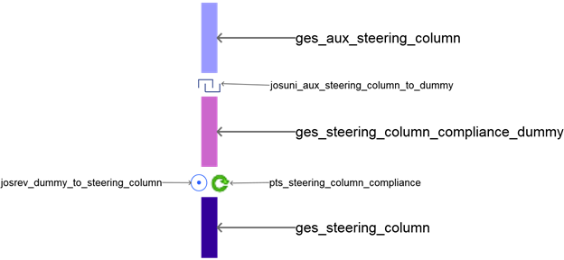
Figure 1 Steering column compliance topology
The steering column compliance can be of type Linear or Nonlinear. This can be toggled by using parameter variable 'pvs_steering_column_compliance'. Where, '0', '1' and '2' are mapped to None, Linear and Nonlinear respectively.
The point torque 'pts_steering_column_compliance' actuator introduce required torque depending upon the selection of the steering column compliance.
The parameters required for the compliance are torsional stiffness (gps_steering_column_comp_kt), torsional damping (gps_steering_column_comp_ct) and nonlinear spline (gss_steering_column_compliance). These are read from "steer_compliance.ste" file stored in steering_assist.tbl of the acar_concept database.
Intermediate shaft compliance (i-shaft compliance)
I-shaft compliance is introduced in between upper and lower intermediate shafts. This can be toggled by using parameter variable 'pvs_ishaft_compliance'. Where, '0', '1', '2' and '3' are mapped to None, Lash, Linear and Nonlinear respectively.
The point torque 'pts_ishaft_compliance' actuator introduce required torque depending upon the selection of the I-shaft compliance.
The parameters required for the compliance are:
- torsional stiffness (gps_ishaft_comp_kt),
- torsional damping (gps_ishaft_comp_ct) and
- nonlinear spline (gss_ishaft_compliance).
These are read from "steer_compliance.ste" file stored in steering_assist.tbl of the acar_concept database.
Upper/Lower Intermediate shaft compliance
In the Rack and Pinion Tilt 3 Universal Joint Steering System the intermediate shaft compliance is divided into two separate design options upper and lower intermediate shaft compliance. This can be toggled individually by using parameter variable 'pvs_upper_intermediate_shaft_compliance' and 'pvs_lower_intermediate_shaft_compliance' for upper and lower intermediate shaft compliance respectively. Where, '0', '1' and '2' are mapped to None, Linear and Nonlinear respectively.
The point torque 'pts_upper_ishaft_compliance' and 'pts_lower_ishaft_compliance' actuators introduce required torque depending upon the selection of the choices of the upper and lower intermediate shaft compliances.
The parameters required for the compliance are:
- torsional stiffness (gps_upper_ishaft_comp_kt, gps_lower_ishaft_comp_kt),
- torsional damping (gps_upper_ishaft_comp_ct, gps_lower_ishaft_comp_ct) and
- nonlinear spline (gss_upper_ishaft_compliance, gss_lower_ishaft_compliance).
These are read from "steer_compliance.ste" file stored in steering_assist.tbl of the acar_concept database.
Intermediate shaft Lash
The lash is introduced between upper and lower intermediate shafts. This can be toggled by using parameter variable 'pvs_ishaft_compliance''. The point torque 'pts_ishaft_compliance' actuator introduces required torque depending upon the lash value that calculates output angle based on the 3D spline (gss_lash). You can specify the desired lash value and the nature of spline in the property file (steer_compliance.ste).
The lash is active if the 'gps_ishaft_lash' value is greater than zero.
The following diagram shows implementation of Intermediate shaft compliance and lash (Figure 2)
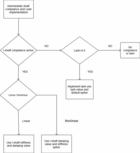
Figure 2 Intermediate shaft compliance and lash implementation flow chart.
Column compliance
The column compliance is induced in between intermediate shaft lower and intermediate shaft lower dummy. This can be toggled by using parameter variable 'pvs_column_compliance'. Where, '0', '1' and '2' are mapped to None, Linear and Nonlinear respectively.
The point torque 'pts_column_compliance' actuator introduces required torque depending upon the selection of the choices of the column compliance.
The parameters required for the compliance are:
- torsional stiffness (gps_column_comp_kt),
- torsional damping (gps_column_comp_ct) and
- nonlinear spline (gss_column_compliance).
These are read from "steer_compliance.ste" file stored in steering_assist.tbl of the acar_concept database.
Shaft compliance (Sector Shaft)
In the Relay and Pitman Advanced Steering System and Relay and Pitman Simple Steering System, shaft compliance is induced in between sector shaft and pitman arm. This can be toggled by using parameter variable 'pvs_shaft_compliance'. Where, '0' and '1' are mapped to Off and On respectively.
The torsion spring 'ues_shaft_compliance_relay' for relay and 'ues_shaft_compliance_pitman' for pitman configuration introduces required torque depending upon the stiffness and damping value.
The parameters required for the compliance are torsional stiffness, torsional damping or nonlinear spline which can be define itself in torsion spring. The variable 'pvs_shaft_compliance_stiffness' should be greater than '0.0' if the shaft compliance is 'on', else it will be considered as 'off'.
The 'pvs_shaft_compliance_stop_angle' value is used to apply torque through point torque 'pts_sector_shaft_stop_angle' if the sector shaft rotate through the specified value in either directions.
Friction
The modelling fidelity can be improved to accurately model on center handling, steering performance, and drift by turning on the friction. The friction between lower, upper u-joint and steering wheel can be activated by using parameter variable 'pvs_lower_ujoint_friction_active' for lower u-joint, 'pvs_upper_ujoint_friction_active' for upper u-joint and 'pvs_steering_wheel_friction_active' for steering wheel.
For Relay and Pitman Advanced Steering System and Relay and Pitman Simple Steering System additional friction forces related to steering gear are modeled. The friction between steering shaft, piston, sector shaft and idler arm can be activated by using parameter variable 'pvs_gear_input_friction' for housing to input shaft joint, 'pvs_piston_friction' for piston to gear housing joint, 'pvs_sector_shaft_friction' for sector to gear housing joint and 'pvs_idler_arm_friction' for idler to body joint. Idler arm friction can be used only if the pitman type gear configuration is selected.
You can modify the parameters of the friction 'frs_lower_ujoint', 'frs_upper_ujoint', 'frs_steering_wheel', 'frs_gear_input_friction', 'frs_piston_friction', 'frs_sector_shaft_friction' and 'frs_idler_arm_friction' selectively.
Rack housing midmount
The compliance between rack housing and body/subframe can be improved by activating rack housing mid-mounts using parameter variable 'pvs_rack_housing_midmount'. Where, '0', '1' and '2' are mapped to None, Mid-Mount One and Mid-Mount Both. The position of the mid-mounts can be controlled by using hardpoints 'hps_rack_house_mid_mount_1' and 'hps_rack_house_mid_mount_2' respectively.
Upper/Lower Isolator
In the Rack and Pinion Tilt 3 Universal Joint Steering System the isolators are provided for upper and lower intermediate shaft. The upper and lower isolator can be individually activated using parameter variable 'pvs_upper_isolator' and 'pvs_lower_isolator' respectively. When the upper isolator is active the fixed joint between "upper_isolator_dummy" and "upper_ishaft_compliance" parts is replaced with the bushing. Similarly, lower isolator bushing is attached between "lower_isolator_dummy" and "intermediate_shaft_lower" parts.
Dash seal compliance
In the Rack and Pinion Tilt 3 Universal Joint Steering System dash seal compliance option is provided. You can connect dash seal to support upper/lower intermediate shaft or steering shaft using switch part as per requirement. By default the dash seal compliance is active. You can toggle it by using parameter variable 'pvs_dash_seal_compliance'. If you deactivate the compliance then dash seal part is connected using fixed joint to the body if you use the steering in full-vehicle assemblies.
Also you can simulate real condition by activating the friction in dash seal compliance. This will induced friction between connected part and the dash seal part. You can toggle it by using parameter variable 'pvs_dash_seal_friction'.
Note: | The bushing (bgs_dash_seal_bushing) and joint (joscyl_upper_ishaft_dash_seal) used in dash seal compliance makes use of user function for proper orientation. It is recommended that you shouldn't modify orientation dependency of those busing and joint. |
U-Joint phasing
To simulate the installation of steering column universal joints, your template based product offers the user optional specification of U-Joint phase angles. The user can specify 2 phase angles for Rack and Pinion Advanced Steering System and 3 phase angles for Rack and Pinion Tilt 3 Universal Joint Steering System.
For 2 U-joint phasing system the first phase angle applies to the upper u-joint, the second phase angle applies to the lower u-joint. Similarly, for 3 U-joint phasing system the first phase angle applies to the upper u-joint, the second phase angle applies to the middle u-joint and the third phase angle applies to lower u-joint.
The orientation is such that a positive angle indicates clockwise rotation of the u-joint looking down the steering column. The second phase angle is defined as being relative to the first phase angle (Figure 3) and the third phase angle is defined as being relative to second phase angle.
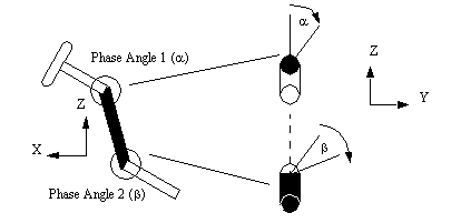
Figure 3 U-Joint phasing
The U-joint phasing can be activated by using parameter variable 'pvs_ujoint_phase'. The angles can be specified using parameter variables 'pvs_u_joint_phase_angle_1', 'pvs_u_joint_phase_angle_2', 'pvs_u_joint_phase_angle_3' respectively.
Tilt Bracket Slider Location
In the Rack and Pinion Tilt Bracket Steering System the slider location design option is provided. You can select slider location either at the intermediate or upper steering column shaft to allow articulation of the column during tilt adjustment. You can toggle it by using parameter variable 'pvs_tilt_bracket_slider_location' where, '1' and '2' are mapped to Upper Shaft, and Intermediate Shaft.
When you select Upper Shaft, one translation degree of freedom is released between steering wheel and auxiliary steering column and when you select Intermediate Shaft one translation degree of freedom is released between intermediate shaft lower and intermediate shaft upper.
Also you can set angle of Tilt Bracket to Body during runtime using Tilt Bracket Angle. The parameter variable 'pvs_tilt_bracket_angle' is used to set tilt angle.
Torsion Bar
The torsion bar can be used to specify different torsion bar modeling options like linear, linear with stop angle, geometric, geometric with stop angle and nonlinear spline options for providing compliance between steering shaft and pinion shaft.
Steering Assist
The force or torque actuator provides the steering assist force to the rack or torque to the motor. The below figure shows the flow chart of steering assist implementation. The steering assist has different options like None, Hydraulic, EPAS Column, EPAS Rack Simple, EPAS Rack Complex, EPAS Pinion and EPAS Second Pinion.
When "None" is selected, it deactivates steering assist force. When "Hydraulic" is selected, it activates steering assist force at the rack. When different EPAS options are selected, it activates respective steering assist torque at the motor.
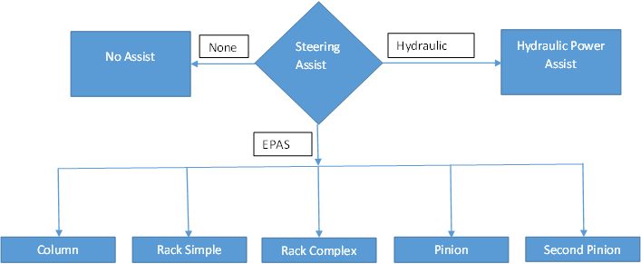
Figure 4 Flow chart of steering assist implementation
The Figure 5 shows the flow chart of hydraulic assist Implementation. It directly apply steering assist force to the rack.
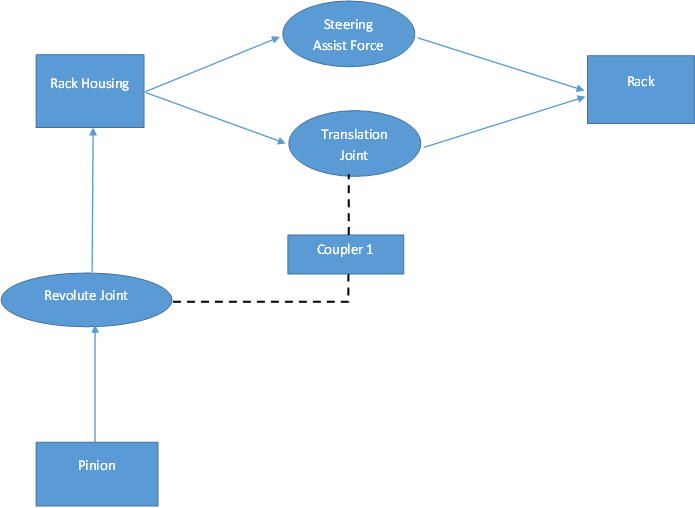
Figure 5 Flow chart of hydraulic assist implementation
The Figure 6 shows the flow chart of EPAS Column Assist Implementation which applies steering assist torque to the motor.
Note: | For EPAS column assist, the part "Input steering shaft" is fixed to part "Pinion". The revolute joint between "Input steering shaft" and "Rack Housing" is removed. |
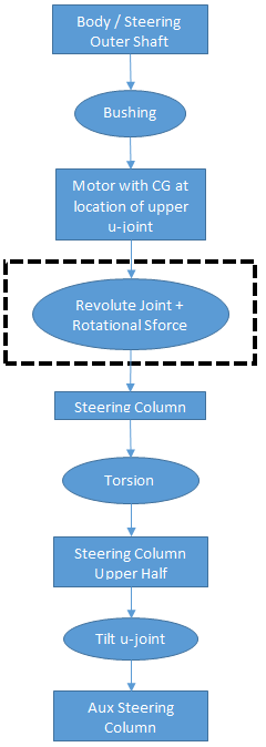
Figure 6 Flow chart of electric column assist implementation
The Figure 7 shows the flow chart of EPAS Rack Simple Assist Implementation which applies steering assist torque to the motor. See EPAS Boost Options (Rotational Sforce) Implementation.
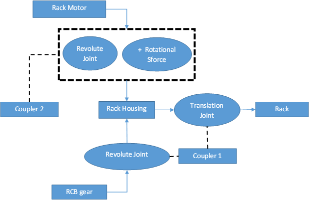
Figure 7 Flow chart of electric rack simple assist implementation
The Figure 8 shows the flow chart of EPAS Rack Complex Assist Implementation which applies steering assist torque to the motor. See EPAS Boost Options (Rotational Sforce) Implementation.
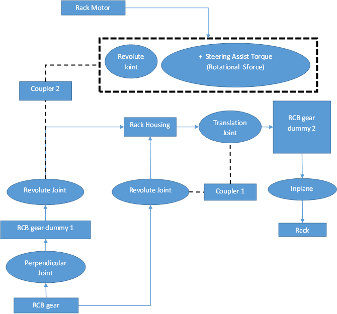
Figure 8 Flow chart of electric rack complex assist implementation
The Figure 9 shows the flow chart of EPAS Pinion Assist Implementation which applies steering assist torque to the pinion motor. See EPAS Boost Options (Rotational Sforce) Implementation.
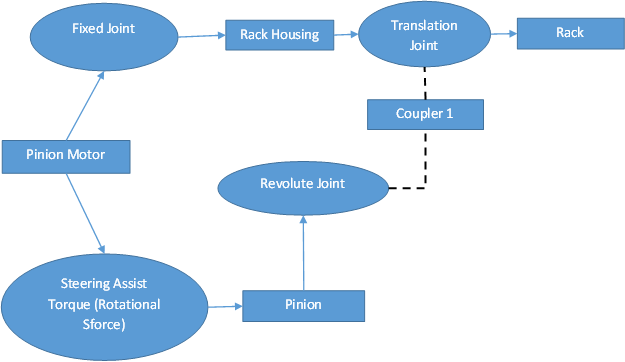
Figure 9 Flow chart of electric pinion assist implementation
The Figure 10 shows the flow chart of EPAS Second Pinion Assist Implementation which applies steering assist torque to the pinion motor.
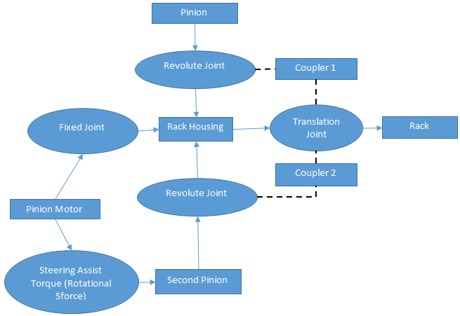
Figure 10 Flow chart of electric second pinion assist implementation
EPAS Boost Type
The flowchart below demonstrates how EPAS Boost Type options used to calculate motor torque (Rotational Sforce) which applies steering assist torque to the respective motor based on the selection of EPAS boost type.
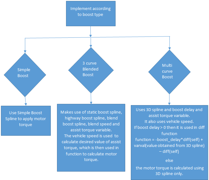
Flow chart of electric boost implementation
The following table shows the design options implemented in the steering templates.
Design Option Name | Choices | Values | Dependent Variable | Description |
|---|---|---|---|---|
Inactive | 0 | steering_column_to_body_damping | Deactivate the steering column to body compliance | |
Active | 1 | This will introduced damping in between steering column part and the body | ||
Steering Column To Body Damping | User-entered real number | Specify damping between steering column and body | ||
None | 0 | Deactivate the intermediate shaft compliance | ||
Lash | 1 | Use lash value and default 3D spline to identify output angle as per the input angle. | ||
Linear | 2 | Use constant value of rotational stiffness and rotational damping | ||
Nonlinear | 3 | Use nonlinear rotational stiffness spline and constant value of rotational damping | ||
None | 0 | Deactivate the intermediate shaft compliance | ||
Linear | 1 | Use constant value of rotational stiffness and rotational damping | ||
Nonlinear | 2 | Use nonlinear rotational stiffness spline and constant value of rotational damping | ||
None | 0 | Deactivate the intermediate shaft compliance | ||
Linear | 1 | Use constant value of rotational stiffness and rotational damping | ||
Nonlinear | 2 | Use nonlinear rotational stiffness spline and constant value of rotational damping | ||
Lower / Upper u-joint and Steering wheel friction | Inactive | 0 | Deactivate the friction of the joints | |
Active | 1 | Activate the friction of the joints | ||
None | 0 | rack mid-mounts are inactive | ||
Mid-Mount One | 1 | One rack mid-mounts active | ||
Mid-Mount Both | 2 | Two rack mid-mounts active | ||
Inactive | 0 | Deactivate the upper/lower isolator | ||
Active | 1 | Activate the upper/lower isolator | ||
Inactive | 0 | Dash seal part is attached with fixed joint to the chassis | ||
Active | 1 | Dash seal part is attached with bushing to the chassis | ||
Inactive | 0 | pvs_u_joint_phase_angle_1, pvs_u_joint_phase_angle_2, pvs_u_joint_phase_angle_3 | Optimum angle is used to orient upper, middle(if present) and lower universal joint | |
Active | 1 | Used user entered phasing angle to orient the universal joints | ||
U Joint Phase Angle 1 | User-entered real number | Specify phasing angle for upper universal joint | ||
U Joint Phase Angle 2 | User-entered real number | Specify phasing angle for lower (middle) universal joint | ||
U Joint Phase Angle 3 | User-entered real number | Specify phasing angle for lower universal joint | ||
None | 0 | Deactivate steering assist force | ||
Hydraulic | 1 | Activate hydraulic steering assist | ||
EPAS Column | 2 | pvs_epas_boost_type | Activate electric column steering assist | |
EPAS Rack Simple | 3 | Activate electric rack steering assist (Simple) | ||
EPAS Rack Complex | 4 | Activate electric rack steering assist (Complex) | ||
EPAS Pinion | 5 | Activate electric pinion steering assist | ||
EPAS Second Pinion | 6 | Activate electric second pinion steering assist | ||
None | 0 | No boost force | ||
Simple | 1 | Use values specified in the [SIMPLE] block | ||
Three Curve | 2 | Use values specified in the [3_CURVE] block | ||
Multi Curve | 3 | Use values specified in the [MULTI_CURVE] | ||
Linear | 1 | Use torsional stiffness value | ||
Linear Using Stop Angle | 2 | Use torsional stiffness value and scale it using values from [TORSION_BAR_SCALING] block | ||
Geometric | 3 | Use calculated value of the torsional stiffness based on the geometrical properties | ||
Geometric Using Stop Angle | 4 | Use calculated value of the torsional stiffness based on the geometrical properties and scale it using values from [TORSION_BAR_SCALING] block | ||
NonLinear | 5 | Use torsional stiffness values from [TORSION_BAR] block | ||
Upper Shaft | 1 | pvs_tilt_bracket_angle | Slider location at Upper shaft between steering wheel and auxiliary steering column parts | |
Intermediate Shaft | 2 | Slider location at intermediate shaft between intermediate shaft lower and intermediate shaft upper parts |