acar_concept database
Aarm_3link Suspension
Overview
Aarm_3link suspension template is a solid axle suspension with a single aarm link and the two longitudinal links. This suspension can be used as a steerable suspension.
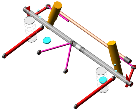
Figure 26 Aarm 3link
Template name
_aarm_3link
Major role
Suspension
Application
Suspension and full-vehicle assemblies
Description
The Aarm _3link suspension template has steerable solid axle with a single aarm link and two longitudinal links. You can use the template as a steerable suspension.
This template has the following design options of driveline activity, hub compliance, panhard rod, steerable axle, bump stopper and rebound stopper.
All bushes are modeled as connectors, this helps in changing connector from bush to joints and vice versa.
Files referenced
Bushings, springs, dampers, bumpstop and reboundstop property files.
Topology
The following tables maps the topology of the 3link suspension.
The joint: | Connects the part: | To the part: |
|---|---|---|
joltra_toe_split | gel_toe_adjuster | gel_tie_rod |
jolrev_upright_to_axle | gel_upright | ges_axle |
jolhoo_tierod_inner | gel_tie_rod | swl_tierod_connection |
jolcyl_lwr_upr_strut | gel_lower_strut | gel_upper_strut |
joltra_tripot_to_differential | gel_tripot | mtl_tripot_to_differential |
jolcon_drive_sft_int_jt | gel_tripot | gel_drive_shaft |
jolcon_drive_sft_otr | gel_drive_shaft | gel_spindle |
Hub Compliance Active | ||
jolsph_hub_compliance | gel_spindle | gel_upright |
Hub Compliance Inactive | ||
jolrev_spindle_upright | gel_spindle | gel_upright |
Parameters
The integer parameter variables allow you to activate and deactivate the various configuration options.
The parameter: | Takes the value: | Its units are: | Description |
|---|---|---|---|
phs_driveline_active | Integer | No units | 0 = No, 1 = Yes |
pvs_hub_compliance | Integer | No units | 0 = Inactive, 1 = Active |
pvs_steerable_axle | Integer | No units | 0 = Inactive, 1 = Active |
pvs_number_of_bumpstops | Integer | No units | 0 = None, 1 = One |
pvs_number_of_reboundstops | Integer | No units | 0 = None, 1 = One |
pv[lr]_toe_angle | Real | Degree | |
pv[lr]_drive_shaft_offset | Real | mm | |
pv[lr]_camber_angle | Real | Degree | |
pvs_hub_compliance_offset | Real | mm |
Communicators
Mount parts provide the connectivity from the template to the body subsystems. Output Communicators publish toe, camber, steer axis, and wheel-center location information to the appropriate subsystems and the test rig. The following table lists the input and output communicators.
The communicator: | Belongs to the class: | Has the role: |
|---|---|---|
ci[lr]_ shock_to_frame | mount | inherit |
ci[lr]_ spring_to_frame | mount | inherit |
cis panhard_to_body | mount | inherit |
ci[lr]_tripot_to_differential | mount | inherit |
ci[lr]_uca_to_frame | mount | inherit |
ci[lr]_trailing_arm_to_body | mount | inherit |
ci[lr]_rearsteer_rack_to_tierod | mount | inherit |
co[lr]_rearsteer_rack_to_axle | mount | inherit |
co[lr]_rearsteer_tierod_inner_loc | location | inherit |
cos_axle | mount | inherit |
co[lr]_kingpin_marker | marker | inherit |
co[lr]_trailing_arm_right | mount | inherit |
co[lr]_camber_angle | parameter_real | inherit |
co[lr]_ride_height_ref | marker | inherit |
co[lr]_suspension_mount | mount | inherit |
co[lr]_suspension_upright | mount | inherit |
co[lr]_toe_angle | parameter_real | inherit |
co[lr]_tripot_to_differential | location | inherit |
co[lr]_wheel_center | location | inherit |
cos_driveline_active | parameter_integer | inherit |
cos_suspension_ parameters_ARRAY | array | inherit |
All-Wheel Drive Driveline System
Overview
The all-wheel drive driveline system template provides an example model of a driveline for all-wheel drive (AWD) vehicles. This is intended for use with suspension templates that do not contain drive shafts.
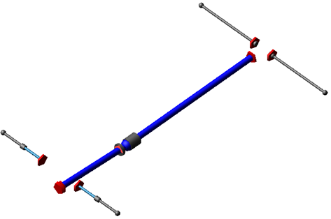
Figure 27 AWD Driveline System
Template name
_driveline_awd
Major role
Driveline
Application
Full-vehicle assemblies
Description
The AWD driveline template is based on the Four-Wheel Drive Driveline System. The only difference is an open center differential that replaces the transfer case, and the addition of rear drive shafts.
Files referenced
Bushing and differential property files
Topology
The AWD driveline template consists of a two-piece prop shaft, a slip yoke, and three differentials. Transmission output torque is applied to the center differential, which splits torque to the front and rear prop shafts, and from there to the front and rear differentials. The prop shaft input part attaches to the powertrain through a revolute joint.
A bearing supports the front prop shaft at its aft end via an inline joint primitive that prevents translation of the front prop shaft perpendicular to the prop shaft's spin axis.
A convel joint transmit the motion to the slip yoke part. The slip yoke supports and transmits torque to the rear prop shaft through a translational joint. The differential input shaft receives torque from the rear prop shaft through a hooke joint.
The differentials includes a limited slip torque based on a viscous clutch operating principal. The differential cases are mounted to switch parts, allowing the user to attach the diff to the powertrain, body, or subframe.
The following table maps the topology of the template, where differences exist relative to the Four-Wheel Drive Driveline System.
The joint: | Connects the part: | To the part: |
|---|---|---|
jo[lr]con_rear_inner_CVJ | ge[lr]_rear_halfshaft | ge[lr]_rear_tripod |
jo[lr]con_rear_outer_CVJ | ge[lr]_rear_halfshaft | mt[lr]_rear_spindle |
jo[lr]tra_rear_diff_to_tripod | ge[lr]_rear_diff_output | ge[lr]_rear_tripod |
josrev_center_diff_input | ges_center_diff_input | sws_center_diff_mount |
All-Wheel Drive (Viscous Coupling) Driveline System
Overview
The all-wheel drive viscous coupling driveline system template provides an example model of a driveline for all-wheel drive (AWD) vehicles. This is intended for use with suspension templates that do not contain drive shafts.
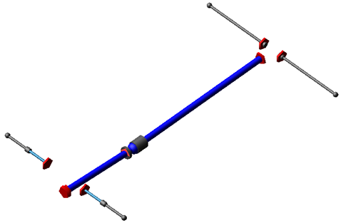
Figure 28 AWD Viscous Coupling Driveline System
Template name
_driveline_awd_viscous_coupling
Major role
Driveline
Application
Full-vehicle assemblies
Description
The AWD Viscous Coupling driveline template is based on the All-Wheel Drive Driveline System. The only difference is a viscous coupling that replaces the center differential.
Files referenced
Bushing and differential property files
Topology
The AWD Viscous Coupling driveline template consists of a two-piece prop shaft, a slip yoke, a viscous coupling, and two differentials. Transmission output torque is applied to the front prop shaft input, which is coupled to the front diff input through a viscous coupling, and from there to the front and rear differentials. The prop shaft input part attaches to the powertrain through a revolute joint.
A bearing supports the front prop shaft at its aft end via an inline joint primitive that prevents translation of the front prop shaft perpendicular to the prop shaft's spin axis.
A convel joint transmit the motion to the slip yoke part. The slip yoke supports and transmits torque to the rear prop shaft through a translational joint. The differential input shaft receives torque from the rear prop shaft through a hooke joint.
The differentials includes a limited slip torque based on a viscous clutch operating principal. The differential cases are mounted to switch parts, allowing the user to attach the diff to the powertrain, body, or subframe.
Anti-roll bar system (discrete flexible links)
The discrete flexible link anti-roll bar template represents a bar fitted transversely to the suspension. The bar is made out of steel or a user-defined material. The bar is installed in a vehicle to reduce the roll of the vehicle body as the vehicle takes a corner. It increases suspension roll rate.
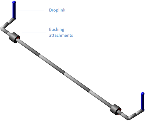
Figure 29 Anti-roll bar system (discrete flexible links)
Template name
_arb_discrete_flexible_links
Major role
antirollbar
Application
Suspension and full-vehicle analyses
Description
This anti-roll bar template provides a beam element model of anti-roll bar (also known as stabilizer bar). It consists of several rigid body parts connected by beam forces. The outer radius and inner radius are parameterized, allowing you to model a solid or hollow cross-section.
Files referenced
Bushing property files
Topology
Left and right bushings attach the bar to the body or to the suspension subframe. Drop links transmit the suspension motion to the bar ends. The drop links attach to the suspension with spherical joints and to the bar ends with convel joints.
The following table maps the topology of the anti-roll bar system template.
The joint: | Connects part: | To part: |
|---|---|---|
jo[lr]sph_droplink_upper_ball | ge[lr]_droplink | mt[lr]_droplink_to_suspension |
jo[lr]con_droplink_to_arb | ge[lr]_droplink | ge[lr]_arb |
Limitations
The anti-roll bar system template represents an approximation of a stabilizer bar. For more complex solutions (for example, complex ARB geometry or large deflections), you would need to create a more accurate representation of the bar using flexible bodies or FE parts.
Communicators
Mount parts provide the connectivity to the suspension subsystems. An output Communicators exports information about the location of the ARB pick-up point.
The following table lists the communicators that the template uses.
The communicator: | Belongs to the class: | Has the role: |
|---|---|---|
ci[lr]_arb_bushing_mount | mount | inherit |
ci[lr]_droplink_to_suspension | mount | inherit |
co[lr]_ARB_pickup | location | inherit |
Central_link Suspension
Overview
A Central link suspension uses two lateral and one longitudinal links to hold the wheel carrier and control its movements. A central link is a type of trailing link that is rigidly attached to the wheel carrier and connected to frame with a bush.
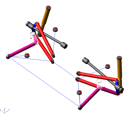
Figure 30 Central link Suspension
Template name
_central_link
Major role
Suspension
Application
Suspension and full-vehicle assemblies
Description
The Central link suspension template represents the most common design for central link suspension. You can use the template as a rear non-steerable suspension. This template has the following design options of driveline activity, subframe, hub compliance, bumpstopper, rebound stopper and springs. All bushes, expect the subframe bushes are modeled as connectors, this helps in switching between bushing and joints.
Files referenced
Bushings, springs, dampers, bumpstop property files.
Topology
The following tables maps the topology of the central link suspension.
The joint | Connects the part: | To the part: |
|---|---|---|
joltra_toe_split | gel_toe_adjuster | mts_subframe_to_body |
joltra_camber_split | lower_lateral_link | gel_camber_adjuster |
josfix_subframe_rigid | ges_subframe | mts_subframe_to_body |
jolcyl_lwr_upr_strut | gel_lower_strut | gel_upper_strut |
joltra_tripot_to_differential | gel_tripot | mtl_tripot_to_differential |
jolcon_drive_sft_int_jt | gel_tripot | gel_drive_shaft |
jolcon_drive_sft_otr | gel_drive_shaft | gel_spindle |
Hub Compliance Active | ||
jolsph_hub_compliance | gel_spindle | gel_upright |
Hub Compliance Inactive | ||
jolrev_spindle_upright | gel_spindle | gel_upright |
Parameters
The integer parameter variables allow you to activate and deactivate the various configuration options.
The parameter: | Takes the value: | Its units are: | Description |
|---|---|---|---|
phs_driveline_active | Integer | No units | 0 = No, 1 = Yes |
phs_subframe | Integer | No units | 0 = None, 1 = Compliant, 2 = Kinematic |
pvs_subframe_midmounts | Integer | No units | 0 = None, 1 = Front Only, 2 = Rear Only, 3 = Both |
pvs_hub_compliance | Integer | No units | 0 = Inactive, 1 = Active |
pvs_number_of_bumpstops | Integer | No units | 0 = None, 1 = One, 2 = Two |
pvs_number_of_reboundstops | Integer | No units | 0 = None, 1 = One, 2 = Two |
pvs_number_of_springs | Integer | No units | 1 = One, 2 = Two |
pv[lr]_toe_angle | Real | Degree | |
pv[lr]_drive_shaft_offset | Real | mm | |
pv[lr]_camber_angle | Real | Degree | |
pvs_hub_compliance_offset | Real | mm |
Communicators
Mount parts provide the connectivity from the template to the body subsystems. Output communicators publish toe, camber, steer axis, and wheel-center location information to the appropriate subsystems and the test rig. The following table lists the input and output communicators.
The communicator: | Belongs to the class: | Has the role: |
|---|---|---|
ci[lr]_strut_to_body | mount | inherit |
ci[lr]_tripot_to_differential | mount | inherit |
cis_subframe_to_body | mount | inherit |
cis_chassis_reference | marker | inherit |
co[lr]_camber_angle | parameter_real | inherit |
co[lr]_ride_height_ref | marker | inherit |
co[lr]_suspension_mount | mount | inherit |
co[lr]_suspension_upright | mount | inherit |
co[lr]_toe_angle | parameter_real | inherit |
co[lr]_tripot_to_differential | location | inherit |
co[lr]_wheel_center | location | inherit |
cos_driveline_active | parameter_integer | inherit |
cos_suspension_ parameters_ARRAY | array | inherit |
Disc-Brake System
Overview
This disc-brake system is a more advanced version of the template in the acar_shared database.
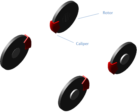
Figure 31 Disc-Brake System
Template name
_brake_system_4Wdisk_calipers
Major role
brake_system
Application
Full-vehicle Analysis to simulate the effect of braking on the dynamics of the vehicle.
Description
This disc-brake system represents a more advanced model of a brake system than the template in the acar_shared database. Instead of a rotational torque between the caliper and the rotor, this model uses joint friction. This approach has the advantage of providing braking torque at zero speed. Other advantages of this model include:
■Rotor and caliper mass can be specified
■Caliper mounting angle is adjustable
■Calipers can be modeled as fixed or floating
■Completely parametric brake force calculation
■Curve of master cylinder pressure vs. brake demand stored in a property file
■Curve of rear brake line pressure vs. master cylinder pressure stored in a property file
■Plant Inputs/Outputs for connection to ABS/electronic braking controller
Files referenced
Brake pressure property file
Topology
The caliper part is mounted to the suspension upright, while the rotor is mounted to the wheel. A revolute joint with friction connects the two parts. A VFORCE between caliper and rotor provides the brake force, which is used to generate friction in the revolute joint.
Parameters
The toe and camber values that the suspension subsystem publishes define the spin axis orientation. The braking force is expressed as a function of a number of parameters.
The following table lists the parameters in the template.
The parameter: | Takes the value: | Its units are: | Description: |
|---|---|---|---|
brake_pressure_input_type | Integer | No units | 1=pressure from spline 2=input from external control system |
front_brake_effective_radius | Real | length | |
front_brake_friction_coefficient | Real | No units | |
front_caliper_floating | Integer | No units | 0=Fixed caliper 1=Floating caliper |
front_caliper_mounting_angle | Real | angle | Clockwise angle from vertical when viewed from the left |
front_piston_area | Real | area | |
front_rotor_hub_wheel_offset | Real | length | |
front_rotor_hub_width | Real | length | |
front_rotor_width | Real | length | |
max_brake_value | Real | No units | |
number_of_pistons_front | Integer | No units | |
number_of_pistons_rear | Integer | No units | |
rear_brake_effective_radius | Real | length | |
rear_brake_friction_coefficient | Real | No units | |
rear_caliper_floating | Integer | No units | 0=Fixed caliper 1=Floating caliper |
rear_caliper_mounting_angle | Real | angle | Clockwise angle from vertical when viewed from the left |
rear_piston_area | Real | area | |
rear_rotor_hub_wheel_offset | Real | length | |
rear_rotor_hub_width | Real | length | |
rear_rotor_width | Real | length |
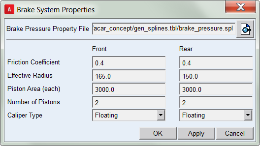
Many of these properties can be set in a single dialog box included in this template:
Limitations
If you set the caliper mass to a value greater than zero, any roll angle or lateral acceleration will produce a small braking torque as the caliper is being pulled away from the rotor.
Communicators
Mount parts provide the connectivity between the template and suspension subsystems. Input Communicators receive information about the toe and camber suspension orientation and the wheel-center location. The input to the brake system is through a brake demand input communicator.
The following table lists the communicators in the template.
The following table lists the communicators in the template.
The communicator: | Belongs to the class: | Has the role: |
|---|---|---|
ci[lr]_front_camber_angle | parameter_real | front |
ci[lr]_front_rotor_to_wheel | mount | front |
ci[lr]_front_toe_angle | parameter_real | front |
ci[lr]_front_wheel_center | location | front |
ci[lr]_front_suspension_ upright | mount | front |
ci[lr]_rear_rotor_ro_wheel | mount | rear |
ci[lr]_rear_suspension_ upright | mount | rear |
ci[lr]_rear_toe_angle | parameter_real | rear |
ci[lr]_rear_camber_angle | parameter_real | rear |
ci[lr]_rear_wheel_center | location | rear |
cis_brake_demand | solver_variable | any |
cos_brake_bias | parameter_real | any |
cos_max_brake_value | parameter_real | inherit |
cos_max_front_brake_torque | parameter_real | any |
cos_max_rear_brake_torque | parameter_real | any |
Notes: | The torque on the rotor depends on a number of parameters. The right front brake force function is: F = IF(pvs_front_caliper_floating:1,1,2) * -pvs_front_piston_area * pvs_number_of_pistons_front * right_front_brake_line_pressure where: right_front_brake_line_pressure is calculated as follows: IF(pvs_brake_pressure_input_type - 2: right_front_brake_line_pressure_Spline, right_front_brake_line_pressure_PINPUT, 0) where: right_front_brake_line_pressure_Spline is calculated as follows: AKISPL(brake_demand, 0, gss_master_cylinder_pressure) and right_front_brake_line_pressure_PINPUT takes a signal from an optional external controller. This braking force is applied between the caliper and rotor, providing the reaction load to the joint friction. The friction torque is then calculated as follows: T = F * pvs_front_brake_friction_coefficient * pvs_front_brake_effective_radius where: the torque is always opposed to the direction of rotation. |
Detailed Brake
Overview
This template is an enhanced version of Disc-Brake System template available in acar shared data base.
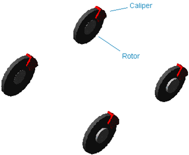
Figure 32 Brake System
Template name
_detailed_brake
Major role
brake_system
Application
Full-vehicle Analysis to simulate the effect of braking on the dynamics of the vehicle.
Description
This template is an enhanced version of Disc-Brake System template available in acar shared data base, with the addition of below design Options:
Valve Gain Type
The simple brake system has 2 pressure valves, the vacuum booster and the proportioning valve.
Note: | For each of these valves you can relate the input pressure to the output pressure with either a spline or a bilinear function. |
For the spline method, you will need to modify general splines and specify the spline in property file (example: mdids://acar_concept/gen_splines.tbl/detailed_brake_data.spl).
The following splines are used for this method:
gss_vacuum_booster_spline, gss_proportioning_valve_spline
For the bilinear method, you need to specify initial gain, final gain, and pressure break point. The following parameters are used for this method:
Vacuum Booster Initial Gain, Vacuum Booster Pressure Break Point, Vacuum Booster Final Gain, Proportioning Valve Initial Gain, Proportioning Valve Pressure Break Point and Proportioning Valve Final Gain
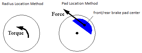
Pad Location Method
Two location methods are provided: radius or XYZ.
For the radius method you supply the distance from the wheel center to the pad center. The brake torque is calculated by multiplying this distance by the friction force. The following parameters are used for this method:
Front Pad Radius and Rear Pad Radius
With the XYZ method you specify the actual geometric center of the brake pad. A force is applied at this point, tangent to the line connecting the wheel center and the pad center. The force is applied in the XZ plane.
Files referenced
None
Topology
Refer brake_system_4Wdisk template online document.
Parameters
The following table lists the additional parameters to Disc-Brake System template available in acar shared data base.
The parameter: | Takes the value: | Its units are: | Description: |
|---|---|---|---|
pvs_vacuum_booster_gain_method | Integer | No units | 0 = Bilinear 1 = Spline |
pvs_proportioning_valve_gain_method | Integer | No units | 0 = Bilinear 1 = Spline |
pvs_rear_pad_location_method | Integer | No units | 0 = radius 1 = XYZ location |
pvs_front_pad_location_method | Integer | No units | 0 = radius 1 = XYZ location |
pvs_brake_proportioning_method | Integer | No units | 0 = Constant 1 = Spline |
Pv[lr]_front_pad_radius | Real | Length | Pad radius |
Pv[lr]_rear_pad_radius | Real | Length | Pad radius |
pvs_master_cyl_diameter | Real | Length | Diameter of master cylinder |
Pv[lr]_front_cyl_diameter | Real | Length | Diameter of front cylinder |
Pv[lr]_rear_cyl_diameter | Real | Length | Diameter of rear cylinder |
pvs_pedal_ratio | Real | No units | Pedal Lever Force Ratio |
pvs_master_cyl_efficiency | Real | No units | Pedal Force to Master Cylinder efficiency |
pvs_master_to_front_cyl_efficiency | Real | No units | Master Cylinder to Front Wheel efficiency |
pvs_prop_valve_efficiency | Real | No units | Proportioning Valve efficiency |
Pv[lr]_front_brake_factor | Real | No units | Front Brake Factor (2*mu for symmetric pad) |
Pv[lr]_rear_brake_factor | Real | No units | Rear Brake Factor (2*mu for symmetric pad) |
pvs_pv_initial_gain | Real | No units | Proportioning Valve Initial Gain |
pvs_pv_final_gain | Real | No units | Proportioning Valve final Gain |
pvs_pv_break_point | Real | No units | Proportioning Valve Pressure Break Point |
pvs_vb_initial_gain | Real | No units | Vacuum Booster Initial Gain |
pvs_vb_final_gain | Real | No units | Vacuum Booster final Gain |
pvs_bv_break_point | Real | No units | Vacuum Booster Pressure Break Point |
Communicators
Refer Disc-Brake System template online document.
Detailed Engine
Overview
The detailed engine template is an engine-only powertrain template (that is, the transmission is not included). It models an inline four cylinder engine with a rotating crankshaft, connecting rods, pistons, and cylinder combustion pressure to produce power.
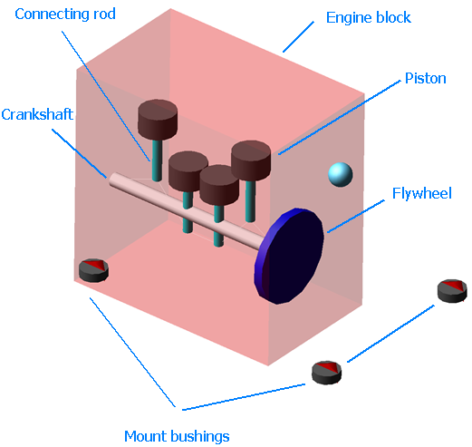
Figure 33 Detailed Engine
Template name
_detailed_engine
Major role
Powertrain
Application
Full-vehicle assemblies
Description
This template includes a rotating crankshaft with reciprocating pistons to model an inline four-cylinder engine. A 3D curve of cylinder pressure vs. crank angle and RPM is scaled by throttle demand to produce power. A drag torque as function of RPM and throttle demand acts on the crankshaft. For quasi-static analyses (where the crankshaft speed is zero), the model includes a conventional engine torque curve as function of RPM and throttle demand.
Files referenced
<acar_shared>/bushings.tbl/MDI_engine_mount.bus
<acar_concept>/powertrains.tbl/I4_118HP_150Nm.pwr
<acar_concept>/powertrains.tbl/gas_force_sample.gpf
<acar_concept>/powertrains.tbl/engine_drag.pwr
Topology
The engine block is attached to the vehicle chassis through four bushings. The crankshaft attaches to the engine block via a revolute joint. The connecting rods attach to the crankshaft via revolute joints. Piston pins attach to the connecting rods via cylindrical joints, and to the pistons via fixed joints. Pistons are constrained to the cylinder axis using primitive joints.
Parameters
The following table lists the parameters in the template.
The parameter: | Takes the value: | Its units are: | Description: |
|---|---|---|---|
bore_spacing | Real | length | distance between cylinder bore centers |
crankshaft_omega_time_constant | Real | time | used to produce low-pass filtered RPM and torque state variables |
downshift_RPM | Real | none | engine RPM at which the driver should downshift |
engine_depth | Real | length | used to size the engine block graphic |
engine_height | Real | length | used to size the engine block graphic |
engine_idle_speed | Real | none | engine RPM at idle |
engine_offset_x | Real | length | used to locate the engine block graphic |
engine_offset_y | Real | length | used to locate the engine block graphic |
engine_offset_z | Real | length | used to locate the engine block graphic |
engine_rev_limit | Real | none | engine RPM at the rev limit |
engine_stall_speed | Real | none | engine RPM at stall |
engine_width | Real | length | used to size the engine block graphic |
idle_error_control | Real | none | used in a feedback control on engine idle speed |
init_Crank_n1_angle | Real | angle | angle of the 1st crankshaft throw |
init_Crank_n2_angle | Real | angle | angle of the 2nd crankshaft throw |
init_Crank_n3_angle | Real | angle | angle of the 3rd crankshaft throw |
init_Crank_n4_angle | Real | angle | angle of the 4th crankshaft throw |
max_throttle | Real | none | max throttle value |
Piston_Diameter | Real | length | used to convert combustion pressure to force |
TDC_Height | Real | length | used to locate the piston forces |
upshift_RPM | Real | none | engine RPM at which the driver should upshift |
Limitations
The detailed engine template uses a number of rotating parts. If the engine dynamics are not of interest to you, then it is more efficient to use a simpler powertrain template, because the rotating parts might slow the numerical integration during the Analysis.
The combustion pressure is scaled linearly by throttle demand, assuming the pressure defined in the property file is at wide open throttle. Users may wish to define a non-linear relationship to scale combustion pressure with respect to throttle demand.
No counter-balances or balance shafts are included in this template.
Communicators
The following table lists the input and output communicators.
The communicator: | Belongs to the class: | Has the role: | Matching names: |
|---|---|---|---|
cis_initial_engine_rpm | parameter_real | any | initial_engine_rpm |
cis_powertrain_to_body | mount | inherit | powertrain_to_body |
cis_throttle_demand | solver_variable | any | throttle_demand |
cis_transmission_input_omega | solver_variable | any | transmission_input_omega |
cos_crankshaft_reference | location | any | crankshaft_reference |
cos_crankshaft_torque | solver_variable | inherit | crankshaft_torque |
cos_downshift_RPM | parameter_real | inherit | downshift_RPM |
cos_engine_block | mount | any | engine, engine_block, powertrain |
cos_engine_idle_speed | parameter_real | any | engine_idle_rpm |
cos_engine_map | spline | any | engine_map |
cos_engine_maximum_braking_torque | solver_variable | inherit | engine_maximum_braking_torque |
cos_engine_maximum_driving_torque | solver_variable | inherit | engine_maximum_driving_torque |
cos_engine_rpm | solver_variable | any | engine_rpm |
cos_engine_speed | solver_variable | any | engine_speed |
cos_engine_speed_limit | parameter_real | any | engine_speed_limit, engine_revlimit_rpm |
cos_engine_stall_speed | parameter_real | any | engine_stall_speed |
cos_flywheel | mount | any | flywheel |
cos_max_throttle | parameter_real | any | max_throttle |
cos_upshift_RPM | parameter_real | inherit | upshift_RPM |
Double Wishbone Advanced Suspension
Overview
The double wishbone advanced suspension template is an enhanced version of the standard Double-Wishbone Suspension.
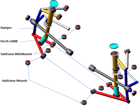
Figure 34 Double-Wishbone Suspension
Template name
_double_wishbone_advanced
Major role
Suspension
Application
Suspension and full-vehicle assemblies
Description
This template is identical to the double wishbone template except for the addition of design options like lower control arm (LCA) configuration options, upper control arm (UCA) configuration options, upper control arm attachment options, Perch - LSMB (Lower Shock Mounting Bracket), torsion bar and subframe.
The LCA is modeled with four configuration options: single ball joint, dual ball joint, dual link with compression and dual link with tension strut. These configurations can be changed using the design options Lower Control Arm Configuration.
The UCA are modeled with two configuration options: single ball joint and dual ball join. These configurations can be changed using the design options Upper Control Arm Configuration.
The UCA has two attachment options: subframe and frame, which is controlled using a switch part. At the subsystem level, modify the switch part to switch between subframe and frame.
Torsion bar design option activates torsion beam spring and deactivates coil spring. Lower attachment of torsion beam spring is controlled by using a switch part. Upper attachment is always connected to the cross member.
You can activate or deactivate the effect of Hub Compliance using the pvs_hub_compliance parameter variable.
You can change current mode of Subframe activity to None, Compliant or Kinematic. You can change number of Subframe MidMounts to none, front only, rear only or both.
You can toggle Perch - LSMB (Lower Shock Mounting Bracket).
Files referenced
Bushings, springs, dampers, and bumpstop property files.
Topology
The topology is identical to the Double-Wishbone Suspension template except UCA attachment options, LCA and UCA configurations.
The following table details the topologies for LCA and UCA configuration options.
Design Option | The joint: | Connects the part: | To the part: |
|---|---|---|---|
LCA Single Ball Joint Configuration  | jolrev_lca | gel_lower_control_arm | sws_subframe_attachment_option |
jolhoo_lwr_strut_1 | gel_lower_strut | gel_lower_control_arm | |
LCA Dual Ball Joint Configuration 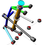 | jolhoo_link_2_inner | gel_lca_link | sws_subframe_attachment_option |
jolhoo_lca_link_2 | gel_lower_control_arm | sws_subframe_attachment_option | |
jolsph_link_2_balljoint | gel_lca_link_2 | gel_upright | |
jolhoo_lwr_strut_2 | gel_lower_strut | gel_upright | |
LCA Dual Link with compression Configuration 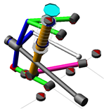 | jolcyl_lca_compression_inner | gel_lower_control_arm | sws_subframe_attachment_option |
jolsph_compression_inner | gel_lca_compression_bar | sws_subframe_attachment_option | |
jolhoo_lwr_strut_3 | gel_lower_strut | gel_lower_control_arm | |
jolhoo_compression_outer | gel_lca_compression_bar | gel_lower_control_arm | |
LCA Dual Link with Tension strut Configuration 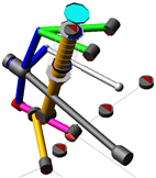 | jolcyl_lca_tension_inner | gel_lower_control_arm | sws_subframe_attachment_option |
jolsph_tension_inner | gel_lca_tension_strut | sws_subframe_attachment_option | |
jolhoo_tension_outer | gel_lca_tension_strut | gel_lower_control_arm | |
jolhoo_lwe_strut_4 | gel_lower_strut | gel_lower_control_arm | |
Hub Compliance Active | jolsph_hub_compliance | gel_spindle | gel_upright |
Hub Compliance Inactive | jolrev_spindle_upright | gel_spindle | gel_upright |
UCA Single Ball Joint Configuration 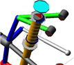 | jolrev_uca | gel_uca_front | swl_uca_attachment_options |
jolfix_uca_fix | gel_uca_front | gel_uca_rear | |
jolsph_uca_balljoint_front | gel_uca_front | gel_upright | |
UCA Dual Ball Joint Configuration  | jolrev_uca_front | gel_uca_front | swl_uca_attachment_options |
jolrev_uca_rear | gel_uca_rear | swl_uca_attachment_options | |
jolsph_uca_balljoint_rear | gel_uca_rear | gel_upright | |
jolsph_uca_balljoint_front | gel_uca_front | gel_upright | |
Torsion bar configuration  | jolfix _torsionbar_bracket_at_frame | gel_ torsionbar_crossmember | mtl_torsionbar_bracket |
Parameters
These integer parameter variables allow you to activate and deactivate the various configuration options. Only those parameters additional to the Double-Wishbone Suspension template are listed below.
The parameter: | Takes the value: | Its units are: | Description |
|---|---|---|---|
pvs_lower_control_arm_configuration | Integer | No units | 1 = Single Ball Joint, 2 = Dual Ball Joint, 3 = Dual Link with Compression, 4 = Dual Link with Tension Bar |
pvs_upper_control_arm_configuration | Integer | No units | 1 = Single Ball Joint, 2 = Dual Ball Joint |
phs_subframe | Integer | No units | 0 = None, 1 = Compliant , 2 = Kinematic |
pvs_subframe_midmounts | Integer | No units | 0 = None, 1 = Front Only, 2 = Rear Only, 3 = Both |
pvs_hub_compliance | Integer | No units | 0 = Inactive, 1 = Active |
pvs_perch | Integer | No units | 0 = Inactive, 1 = Active |
pvs_number_of_bumpstops | Integer | No units | 0 = None, 1 = One, 2 = Two |
pvs_number_of_reboundstops | Integer | No units | 0 = None, 1 = One, 2 = Two |
pvs_torsionbar | Integer | No units | 0 = Inactive, 1 = Active |
Communicators
Refer to the Double-Wishbone Suspension.
Draglink Steering System
The draglink and pitman arm steering system template is a simple steering system derived from the standard Pitman Arm Steering System. It is commonly used in trucks. It consists of a three-bar mechanism: pitman arm, draglink, and tie rod.
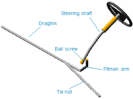
Figure 35 Draglink Steering System
Template name
_draglink_steering
Major role
Steering
Application
Suspension and full-vehicle assemblies
Description
A recirculating ball steering gear transmits motion from the steering wheel to the pitman arm. The pitman arm rotates to impart motion to the draglink. The draglink pulls and pushes the tie rod and steers the wheels.
Files referenced
The point torque actuator references the torsion_bar and steering_assist datablocks in the mdi_steering.ste property file, stored in the Adams Car shared database, under the steer_assists.tbl table or directory.
Topology
The topology is identical to the standard Pitman Arm Steering System, except for the addition of a hydraulic boost force.
Communicators
The following table lists the Communicators in the template.
The communicator: | Belongs to the class: | Has the role: |
|---|---|---|
ci[lr]_tierod_outer | location | inherit |
cis_steering_gear_to_suspension_subframe | mount | inherit |
cis_steering_column_to_ body | mount | inherit |
cos_draglink_to_right_steering_arm_orientation | orientation | inherit |
cos_draglink_to_steering | mount | inherit |
cos_max_steering_angle | parameter_real | inherit |
cos_steering_rack_joint | joint_for_motion | inherit |
cos_steering_wheel | mount | inherit |
cos_steering_wheel_joint | joint_for_motion | inherit |
cos_tierod_to_left_steering_arm_orientation | orientation | inherit |
cos_tierod_to_steering | mount | inherit |
Note: | The draglink steering template does not interface with any of the Adams Car shared database suspension templates because those suspension templates have tie rods. It does interface with the Twin I-Beam Suspension System in the acar_concept database. To correctly assemble the draglink steering to a suspension subsystem from the shared database, you must remove the tie rods from the suspension. The draglink and the tie rod have to be mounted to the left and right upright parts. |
Torsion Bar Double-Wishbone Suspension
Overview
This torsion bar double-wishbone suspension template is a modified version of the standard Torsion Bar Double-Wishbone Suspension. In this template, however, the drive shafts are not modeled. If this suspension is intended to be used as a driven axle, you'll need to include in your full-vehicle assembly a template of major role "driveline".
Figure 36 Torsion Bar Double-Wishbone Suspension
Template name
_double_wishbone_torsion
Major role
Suspension
Application
Suspension and full-vehicle assemblies
Description
Refer to the standard Torsion Bar Double-Wishbone Suspension.
Four-Wheel Drive Driveline System
Overview
The four-wheel drive driveline system template provides an example model of a driveline for four-wheel drive (4WD) vehicles. This is intended for use with suspension templates that do not contain drive shafts.
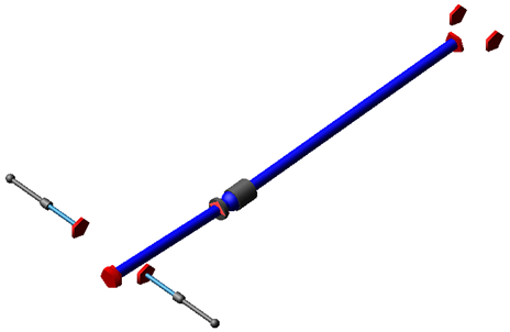
Figure 37 4WD Driveline System
Template name
_driveline_4wd
Major role
Driveline
Application
Full-vehicle assemblies
Description
The transmission output torque is transmitted to the prop shaft, through the transfer case, and from there to the differentials. Front drive shafts are included, and should be connected to the spindles in the front suspension. Rear diff outputs should be connected to the rear axle shafts.
Files referenced
Bushing and differential property files
Topology
The 4WD driveline template consists of a two-piece prop shaft, a slip yoke, and two differentials. Transmission output torque is applied to the prop shaft input part, which feeds into the transfer case, which effectively locks the front and rear prop shaft speeds, and from there to the differentials. The prop shaft input part attaches to the powertrain through a revolute joint.
A bearing supports the front prop shaft at its aft end via an inline joint primitive that prevents translation of the front prop shaft perpendicular to the prop shaft's spin axis.
A convel joint transmit the motion to the slip yoke part. The slip yoke supports and transmits torque to the rear prop shaft through a translational joint. The differential input shaft receives torque from the rear prop shaft through a hooke joint.
The differentials includes a limited slip torque based on a viscous clutch operating principal. The differential cases are mounted to switch parts, allowing the user to attach the diff to the powertrain, body, subframe, or rear axle.
The following table maps the topology of the template.
The joint: | Connects the part: | To the part: |
|---|---|---|
jksinl_support_bearing_to_body | ges_support_bearing | mts_propshaft_support_to_body |
jo[lr]con_front_inner_CVJ | ge[lr]_front_halfshaft | ge[lr]_front_tripod |
jo[lr]con_front_outer_CVJ | ge[lr]_front_halfshaft | mt[lr]_front_spindle |
jo[lr]rev_front_diff_output_to_housing | ge[lr]_front_diff_output | ges_front_diff_housing |
jo[lr]rev_rear_diff_output_to_housing | ge[lr]_rear_diff_output | ges_rear_diff_housing |
jo[lr]tra_front_diff_output_to_tripod | ge[lr]_front_diff_output | ge[lr]_front_tripod |
joscon_propshaft_front_to_yoke | ges_propshaft_front | ges_slip_yoke |
josfix_front_diff_mount | ges_front_diff_housing | sws_front_diff_mount |
josfix_rear_diff_mount | ges_rear_diff_housing | sws_rear_diff_mount |
joshoo_propshaft_at_rear_diff | ges_propshaft_rear | ges_rear_diff_input |
joshoo_propshaft_input_to_front | ges_propshaft_input | ges_propshaft_front |
josinl_support_bearing_to_propshaft_front | ges_support_bearing | ges_propshaft_front |
josinp_support_bearing_location | ges_support_bearing | mts_propshaft_support_to_body |
josori_support_bearing_orientation | ges_support_bearing | mts_propshaft_support_to_body |
josrev_front_diff_input_to_housing | ges_front_diff_input | ges_front_diff_housing |
josrev_propshaft_input_to_trans | ges_propshaft_input | mts_propshaft_input_to_powertrain |
josrev_rear_diff_input_to_housing | ges_rear_diff_input | ges_rear_diff_housing |
jostra_propshaft_rear_to_yoke | ges_propshaft_rear | ges_slip_yoke |
Parameters
The hidden parameter phs_driveline_active has a slightly different usage here than in the acar_shared database. In this case, neither front nor rear suspensions contain drive shafts, so the parameter has been moved here to the driveline template. Both the front and rear suspensions are driven axles, so the variable is a string value instead of an integer value. It contains a list of every driven suspension minor role. In this case, “front,rear”.
The following table lists the parameters in the template.
The parameter | Takes the value: | Its units are: | Description: |
|---|---|---|---|
driveline_active | String | No units | list of every driven suspension minor role |
jack_shaft_active | Integer | No units | 0=no jack shaft 1=jack shaft active |
jack_shaft_length | Real | length | |
propshaft_front_length | Real | length |
Limitations
The driveline template uses a number of rotating parts. If the driveline dynamics are not of interest to you, then it is more efficient to apply direct drive torque to the wheels, because the rotating parts in the template might slow the numerical integration during the Analysis.
Communicators
Output communicators of the type mount publish the left and right output shafts to the suspension templates and subsystems. The following table lists the input and output communicators.
The communicator: | Belongs to the class: | Has the role: |
|---|---|---|
ci[lr]_front_spindle | mount | front |
ci[lr]_front_tire_force | force | front |
ci[lr]_front_wheel_center | location | front |
ci[lr]_halfshaft_outer | location | front |
ci[lr]_rear_tire_force | force | rear |
cis_body | mount | inherit |
cis_driveline_torque | solver_variable | inherit |
cis_front_subframe | mount | front |
cis_powertrain | mount | inherit |
cis_propshaft_input_to_powertrain | mount | inherit |
cis_propshaft_support_to_body | mount | inherit |
cis_rear_axle | mount | rear |
cis_rear_subframe | mount | rear |
cis_transmission_output_location | location | any |
cis_transmission_output_orientation | orientation | any |
co[lr]_diff_output_location | location | rear |
co[lr]_front_tripot_to_differential | mount | front |
co[lr]_rear_diff_output | mount | rear |
cos_diff_input | joint | inherit |
cos_drive_torque_bias_front | parameter_real | any |
cos_final_drive_ratio | parameter_real | any |
cos_transmission_output_omega | solver_variable | any |
Front Driveline System
Overview
This front driveline system template provides an example model of a driveline for front-wheel drive (FWD) vehicles. This is intended for use with a suspension template that does not contain drive shafts.

Figure 38 Front Driveline System
Template name
_driveline_fwd_LSD
Major role
Driveline
Application
Full-vehicle assemblies
Description
An actuator drives the front diff input, which acts through the differential to drive the diff outputs, which are connected to jack shafts and drive shafts, which should be connected to the spindles in the front suspension.
Files referenced
Differential property file
Topology
The front driveline template consists of a differential housing which mounts to a switch part, and diff input/outputs which mount to the housing via revolute joints. The differential includes a viscous limited slip torque. The following table maps the topology of the template.
The joint: | Connects the part: | To the part: |
|---|---|---|
jo[lr]con_inner_CVJ | ge[lr]_halfshaft | ge[lr]_tripod |
jo[lr]con_outer_CVJ | ge[lr]_halfshaft | mt[lr]_spindle |
jo[lr]rev_diff_output_to_housing | ge[lr]_diff_output | ges_diff_housing |
jo[lr]tra_diff_to_tripod | ge[lr]_diff_output | ge[lr]_tripod |
josfix_diff_housing | ges_diff_housing | sws_diff_mount |
josrev_diff_input_to_housing | ges_diff_input | ges_diff_housing |
Parameters
he hidden parameter phs_driveline_active has a slightly different usage here than in the acar_shared database. In this case, the front suspension will not contain drive shafts, so the parameter has been moved here to the driveline template. The variable is a string value instead of an integer value. It contains a list of every driven suspension minor role. In this case, "front".
The following table lists the parameters in the template.
The parameter: | Takes the value: | Its units are: | Description: |
|---|---|---|---|
driveline_active | String | No units | list of every driven suspension minor role |
jack_shaft_active | Integer | No units | 0=no jack shaft 1=jack shaft active |
jack_shaft_length | Real | length | |
propshaft_front_length | Real | length |
Limitations
The front driveline template uses a number of rotating parts. If the driveline dynamics are not of interest to you, then it is more efficient to apply direct drive torque to the wheels, because the rotating parts in the template might slow the numerical integration during the Analysis.
Communicators
The following table lists the input and output communicators.
The communicator: | Belongs to the class: | Has the role: |
|---|---|---|
ci[lr]_halfshaft_outer | location | inherit |
ci[lr]_spindle | mount | inherit |
ci[lr]_tire_force | force | front |
ci[lr]_wheel_center | location | inherit |
cis_driveline_torque | solver_variable | inherit |
cis_body | mount | any |
cis_powertrain | mount | any |
cis_subframe | mount | front |
cis_transmission_output_orientation | orientation | any |
cos_diff_input | joint | inherit |
cos_drive_torque_bias_front | parameter_real | any |
cos_final_drive_ratio | parameter_real | any |
cos_front_diff_housing | mount | any |
cos_transmission_output_omega | solver_variable | any |
Front Driveline for Separate Transmission
Overview
This front driveline template is based on the Front Driveline System above, but it does not contain a torque actuator. Instead it relies on the torque being transmitted into the differential through a mount part.
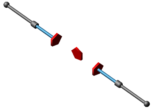
Figure 39 Front Driveline System
Template name
_driveline_fwd_LSD_for_separate_transmission
Major role
Driveline
Application
Full-vehicle assemblies
Description
During assembly, the transmission output is mounted to the differential input, which acts through the differential to drive the diff outputs, which are connected to jack shafts and drive shafts, which should be connected to the spindles in the front suspension.
Files referenced
Differential property file
Topology
The front driveline template consists of a differential housing which mounts to a switch part, and diff input/outputs which mount to the housing via revolute joints. The differential includes a viscous limited slip torque. The following table maps the topology of the template.
The joint: | Connects the part: | To the part: |
|---|---|---|
jo[lr]con_inner_CVJ | ge[lr]_halfshaft | ge[lr]_tripod |
jo[lr]con_outer_CVJ | ge[lr]_halfshaft | mt[lr]_spindle |
jo[lr]rev_diff_output_to_housing | ge[lr]_diff_output | ges_diff_housing |
jo[lr]tra_diff_to_tripod | ge[lr]_diff_output | ge[lr]_tripod |
josfix_diff_housing | ges_diff_housing | sws_diff_mount |
josrev_diff_input_to_housing | ges_diff_input | ges_diff_housing |
Parameters
The hidden parameter phs_driveline_active has a slightly different usage here than in the acar_shared database. In this case, the front suspension will not contain drive shafts, so the parameter has been moved here to the driveline template. The variable is a string value instead of an integer value. It contains a list of every driven suspension minor role. In this case, "front".
The following table lists the parameters in the template.
The parameter: | Takes the value: | Its units are: | Description: |
|---|---|---|---|
driveline_active | String | No units | list of every driven suspension minor role |
jack_shaft_active | Integer | No units | 0=no jack shaft 1=jack shaft active |
jack_shaft_length | Real | length | |
propshaft_front_length | Real | length |
Limitations
The front driveline template uses a number of rotating parts. If the driveline dynamics are not of interest to you, then it is more efficient to apply direct drive torque to the wheels, because the rotating parts in the template might slow the numerical integration during the Analysis.
Communicators
The following table lists the input and output communicators.
The communicator: | Belongs to the class: | Has the role: |
|---|---|---|
ci[lr]_halfshaft_outer | location | inherit |
ci[lr]_spindle | mount | inherit |
ci[lr]_tire_force | force | front |
ci[lr]_wheel_center | location | inherit |
cis_body | mount | any |
cis_diff_input_location | location | any |
cis_powertrain | mount | any |
cis_subframe | mount | front |
cis_transmission_output_orientation | orientation | any |
cos_diff_input | mount | inherit |
cos_diff_input_joint | joint | inherit |
cos_drive_torque_bias_front | parameter_real | any |
cos_final_drive_ratio | parameter_real | any |
cos_front_diff_housing | mount | any |
cos_transmission_output_omega | solver_variable | any |
Rear Driveline System
Overview
This rear driveline system template provides an example model of a driveline for rear-wheel drive (RWD) vehicles. This may be used with a suspension template that does not contain axle shafts.
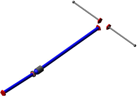
Figure 40 Rear Driveline System
Template name
_driveline_rwd_LSD
Major role
Driveline
Application
Full-vehicle assemblies
Description
An actuator drives the prop shaft, which acts through the differential to drive the diff outputs, which are connected to optional half shafts, which should be connected to the spindles in the rear suspension.
Files referenced
Bushing and differential property files.
Topology
The RWD system consists of a two-piece prop shaft, a slip yoke, and a viscous limited-slip differential. Transmission output torque is applied to the front prop shaft input. The prop shaft input part attaches to the powertrain through a revolute joint. A bearing supports the front prop shaft at its aft end via an inline joint primitive that prevents translation of the front prop shaft perpendicular to the prop shaft's spin axis.
A convel joint transmit the motion to the slip yoke part. The slip yoke supports and transmits torque to the rear prop shaft through a translational joint. The differential input shaft receives torque from the rear prop shaft through a hooke joint. The differential outputs can be connected to axle half shafts in this template, which then connect to spindles in the suspension, or to axle shafts in the suspension template.
The differential includes a limited slip torque based on a viscous clutch operating principal. The differential case is mounted to a switch part, allowing the user to attach the diff to the powertrain, body, or subframe.
The following table maps the topology of the template.
The joint: | Connects the part: | To the part: |
|---|---|---|
jksinl_support_bearing_to_body | ges_support_bearing | mts_propshaft_support_to_body |
jo[lr]con_halfshaft_to_spindle | ge[lr]_halfshaft | mt[lr]_spindle |
jo[lr]con_halfshaft_to_tripod | ge[lr]_front_halfshaft | ge[lr]_tripod |
jo[lr]rev_diff_output_to_housing | ge[lr]_rear_diff_output | ges_rear_diff_housing |
jo[lr]tra_diff_output_to_tripod | ge[lr]_rear_diff_output | ge[lr]_tripod |
joscon_propshaft_front_to_yoke | ges_propshaft_front | ges_slip_yoke |
josfix_rear_diff_mount | ges_rear_diff_housing | sws_rear_diff_mount |
joshoo_propshaft_at_diff | ges_propshaft_rear | ges_rear_diff_input |
joshoo_propshaft_input_to_front | ges_propshaft_input | ges_propshaft_front |
josinl_support_bearing_to_propshaft_front | ges_support_bearing | ges_propshaft_front |
josinp_support_bearing_location | ges_support_bearing | mts_propshaft_support_to_body |
josori_support_bearing_orientation | ges_support_bearing | mts_propshaft_support_to_body |
josrev_propshaft_input_to_trans | ges_propshaft_input | mts_propshaft_input_to_powertrain |
josrev_rear_diff_input_to_housing | ges_rear_diff_input | ges_rear_diff_housing |
jostra_propshaft_rear_to_yoke | ges_propshaft_rear | ges_slip_yoke |
Parameters
The hidden parameter phs_driveline_active has a slightly different usage here than in the acar_shared database. In this case, the rear suspension will not contain drive shafts, so the parameter has been moved here to the driveline template. The variable is a string value instead of an integer value. It contains a list of every driven suspension minor role. In this case, "rear". The pvs_halfshafts_active variable controls the activity of the axle half shafts. If your suspension template does not contain axle shafts, set pvs_halfshafts_active = 1. If you're assembling with a suspension such as the Solid Axle Suspension, set pvs_halfshafts_active = 0.
The following table lists the parameters in the template.
The parameter: | Takes the value: | Its units are: | Description: |
|---|---|---|---|
driveline_active | String | No units | list of every driven suspension minor role |
halfshafts_active | Integer | No units | 0=no half shafts 1=half shafts active |
propshaft_front_length | Real | length |
Limitations
The RWD driveline template uses a number of rotating parts. If the driveline dynamics are not of interest to you, then it is more efficient to apply direct drive torque to the wheels, because the rotating parts in the template might slow the numerical integration during the Analysis.
Communicators
Output communicators of the type mount publish the left and right differential outputs to the suspension templates and subsystems. The following table lists the input and output communicators.
The communicator: | Belongs to the class: | Has the role: |
|---|---|---|
ci[lr]_halfshaft_outer | location | rear |
ci[lr]_spindle | mount | rear |
ci[lr]_tire_force | force | rear |
ci[lr]_wheel_center | location | rear |
cis_body | mount | any |
cis_driveline_torque | solver_variable | inherit |
cis_propshaft_input_to_powertrain | mount | inherit |
cis_propshaft_support_to_body | mount | inherit |
cis_rear_axle | mount | rear |
cis_rear_subframe | mount | rear |
cis_transmission_output_location | location | any |
co[lr]_diff_output | mount | rear |
co[lr]_diff_output_location | location | rear |
cos_drive_torque_bias_front | parameter_real | any |
cos_final_drive_ratio | parameter_real | any |
cos_transmission_output_omega | solver_variable | any |
Engine and Transmission System
Overview
This Engine and Transmission system is a modification of the Powertrain System in the Adams Car shared database. The differential has been removed, so this template should be assembled with a driveline system. This system models an engine and transmission that may be used for with combination of engine layout (transverse front engine, longitudinal front engine, transverse rear engine and so on.) and driveline (FWD, 4WD, AWD and so on.).

Figure 41 Engine and Transmission System
Template name
_engine_transmission
Major role
Powertrain
Application
Full-vehicle assemblies
Description
Refer to the Powertrain System in the Adams Car shared database. The only difference is the removal of the differential. When assembled with a driveline template, the transmission output torque will be reacted against the powertrain part.
Parameters
The parameters are identical to the Powertrain System in the Adams Car shared database, with the addition of pvs_longitudinal. When set to 0, the engine and transmission are oriented in a transverse layout. When set to 1, the engine and transmission are oriented in a longitudinal layout.
Flexible Chassis System
Overview
The flexible chassis system represents a flexible chassis of unibody construction.
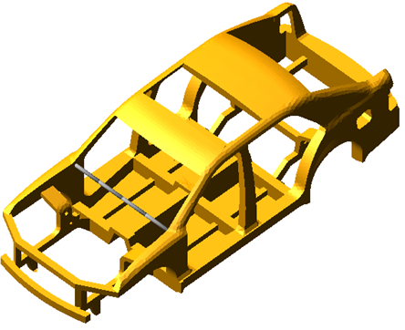
Figure 42 Flexible Chassis
Template name
_flex_chassis
Major role
body
Application
Full-vehicle assemblies.
Description
A single flexible body part models the chassis. The Modal Neutral File file may be replaced with the user’s file.
Files referenced
<acar_concept>/flex_bodys.tbl/BIW_v3_single_precision.mnf
Topology
A small rigid body (ges_stake_body) is fixed to the chassis part to facilitate quasi-static simulations where the chassis is constrained to ground. A non-linear beam representing the instrument panel stiffness connects the left and right sides of the chassis.
Limitations
No aerodynamic forces are modeled in this template.
Communicators
The flexible chassis template defines a series of mount part communicators. The assembly process matches them with the corresponding output communicators created in suspensions, steering, and other subsystems. The following table lists the communicators. Note that the output communicator steering_column_to_body allows the steering column mount part in the steering system to connect to the non-linear beam representing the instrument panel.
The communicator: | Belongs to the class: | Has the role: |
|---|---|---|
cis_std_tire_ref | location | inherit |
co[lr]_bedplate_front_loc | location | inherit |
co[lr]_bedplate_rear_loc | location | inherit |
co[lr]_mount_to_body | mount | any |
cos_body | mount | inherit |
cos_body_stake | mount | any |
cos_chassis_path_reference | mount | inherit |
cos_driver_reference | mount | inherit |
cos_loading_to_body | mount | inherit |
cos_measure_for_distance | mount | inherit |
cos_steering_column_to_body | mount | inherit |
cos_subframe_to_body | mount | inherit |
Hotchkiss Suspension
Overview
The Hotchkiss suspension template is an enhanced version of the standard Leafspring Suspension.
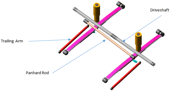
Figure 43 Hotchkiss Suspension
Template name
_hotchkiss_suspension
Major role
Suspension
Application
Suspension and full-vehicle assemblies
Description
The hotchkiss suspension template represents the most common spring design for solid axle suspensions. This template includes steerable uprights, so you can use the template as a steerable front suspension.
Also, there are two configurations for steerable axle which are 'Single Tierod' and 'Split Tierod'. This configuration can be switched as per the design.
To model 'Single Tierod' Configuration set pvs_steerable_axle to 1 and to model 'Split Tierod' Configuration set pvs_steerable_axle to 2.
To model a non-steerable suspension, you may turn off the steering components by setting the parameter variable pvs_steerable_axle to 0.
Apart from above configuration user can even switch the leafspring type. To model simple type of leaf spring, which will turn off the beam elements and turn on the 3-beam configuration by setting the parameter variable pvs_leafspring_type to 0.
Files referenced
Bushings, springs, dampers, bumpstop, and reboundstop property files.
Topology
The topology is identical to the Leafspring Suspension template except leafspring type, Panhard Rod and Trailing Arm configurations.
The following table details the topologies for Leafspring Type, Panhard Rod and Trailing Arm configuration options.
The joint: | Connects the part: | To the part: |
|---|---|---|
jo[lr]tra_toe_split | ge[lr]_toe_adjuster | gev_tierod |
jo[lr]hoo_rack_to_axle | ge[lr]_tierod | sw[lr]_tierod_connection |
jo[lr]tra_tripot_to_differential | ge[lr]_tripot | mt[lr]_tripot_to_differential |
jo[lr]con_drive_sft_int_jt | ge[lr]_tripot | ge[lr]_drive_shaft |
jo[lr]con_drive_sft_otr | ge[lr]_drive_shaft | ge[lr]_spindle |
jo[lr]fix_hub_to_upright | ge[lr]_hub | sw[lr]_upright |
jo[lr]sph_hub_compliance_ns | ge[lr]_hub | sw[lr]_upright |
jo[lr]tra_lower_upper_strut | ge[lr]_lower_shock_body | ge[lr]_upper_shock_body |
jo[lr]fix_hub_to_axle | ge[lr]_hub | sw[lr]_upright |
jo[lr]fix_mid_leaf_to_axle | ges_axle | ge[lr]_mid_leaf |
jo[lr]rev_hub_to_spindle | ge[lr]_hub | ge[lr]_spindle |
josper_panhard_to_axle | ges_panhard_rod | ges_axle |
jo[lr]per_shock_to_frame | ge[lr]_upper_shock_body | mtl_shock_to_frame |
jo[lr]fix_wft | ge[lr]_spindle | ge[lr]_wft |
jo[lr]con_drive_sft_int_jt_comp | ge[lr]_tripot | ge[lr]_drive_shaft_inner |
jo[lr]con_drive_sft_otr_jt_comp | ge[lr]_drive_shaft_outer | ge[lr]_spindle |
Parameters
Toe and camber variables define the wheel spin axis, spindle part, and spindle geometry. The following table lists the parameters in the template.
The parameter: | Takes the value: | Its units are: | Integer |
|---|---|---|---|
pvs_panhard_rod_active | Integer | No units | 0 = Inactive, 1 = Active |
pvs_trailing_arm_active | Integer | No units | 0 = Inactive, 1 = Active |
pvs_steerable_axle | Integer | No units | 0 = Inactive, 1 = Active - Single Tierod 2 = Active - Split Tierod |
phs_driveline_active | Integer | No units | 0 = Inactive, 1 = Active |
pvs_number_of_bumpstops | Integer | No units | 0 = Inactive, 1 = Active with 1 bumpstop |
pvs_number_of_reboundstops | Integer | No units | 0 = Inactive, 1 = Active with 1 reboundstop |
pvs_leafspring_type | Integer | No units | 0 = Simple, 1 = Beam |
pvs_wheel_force_transducer | Integer | No units | 0 = Inactive, 1 = Active |
pvs_halfshaft_compliance | Integer | No units | 0 = Inactive, 1 = Active |
pv[lr]_drive_shaft_offset | Real | Length | |
pvs_second_stage_length | Real | Length | |
pvs_second_stage_rate | Real | Stiffness | |
pvs_outer_wheel_center_offset | Real | Length | |
pvs_wft_offset | Real | Length | |
pv[lr]_halfshaft_length | Real | Length | |
pv[lr]_halfshaft_stiffness | Real | Stiffness |
Communicators
Mount parts provide connectivity from the template to body subsystems and the differential. Output Communicators publish toe, camber, steer axis, and wheel-center location information to the appropriate subsystems and the test rig. The following table lists the input and output communicators.
The communicator: | Belongs to the class: | Has the role: |
|---|---|---|
ci[lr]_trailing_arm_to_body | location | inherit |
ci[lr]_jounce_to_body | mount | inherit |
ci[lr]_rebound_to_body | mount | inherit |
ci[lr]_second_stage_to_frame | mount | inherit |
ci[lr]_tripot_to_differential | mount | inherit |
ci[lr]_rearsteer_rack_to_tierod | mount | inherit |
cis_panhard_to_body | mount | inherit |
cis_test_equipment_gyro | marker | inherit |
co[lr]_kingpin_marker | marker | inherit |
co[lr]_wheel_center_marker | marker | inherit |
co[lr]_rearsteer_tierod_inner_loc | location | inherit |
co[lr]_rearsteer_rack_to_axle | mount | inherit |
co[lr]_outside_wheel_center | location | inherit |
co[lr]_spring_marker_upper | marker | inherit |
co[lr]_spring_marker_lower | marker | inherit |
co[lr]_damper_i | marker | inherit |
co[lr]_damper_j | marker | inherit |
co[lr]_ride_height_ref | marker | inherit |
co[lr]_tripot_to_differential | location | inherit |
co[lr]_arb_bushing_mount | mount | inherit |
cos_wheel_force_transducer | parameter_integer | inherit |
cos_trailing_arm_right | mount | inherit |
cos_trailing_arm_left | mount | inherit |
cos_draglink_pitman_arm | location | inherit |
cos_draglink_tierod | location | inherit |
cos_axle_cm | marker | inherit |
cos_driveline_active | parameter_integer | inherit |
Haltenburger Advanced Steering System
Overview
Haltenburger advanced steering template is an extend version of the relay pitman advanced steering template.
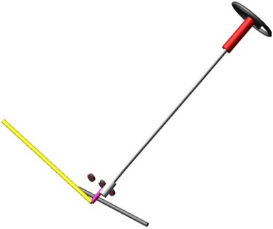
Figure 44 Haltenburger Advanced Steering
Template name
_halt_advanced_steering
Major role
Steering
Application
Suspension and full-vehicle assemblies
Description
This template is an extend version of the relay pitman advanced steering template. It has an additional tierod part that connects drag link to steering arm. In this template, draglink to pitman arm, draglink outer, tierod inner and tierod outer locations are defined using the input communicators. These input communicators should have corresponding output communicators in suspension templates.
Files referenced
Property files, hydraulic_steering_assist.ste or torsion_bar.ste and steering_compliance.ste are stored in the steer_assist.tbl of the acar_concept database. These defines the steering hydraulic assist force, torsion bar and steering compliance respectively.
Topology
The topology for Haltenburger steering mechanism is identical to the relay pitman advanced steering template except for the joint added between tierod and the draglink.
Parameters
Communicators
In addition to above input communicators this template have:
cis_drag_link_to_pitman, cis_drag_link_outer, cis_tierod_inner and cis_tierod_outer.
Haltenburger Simple Steering System
Overview
Haltenburger simple steering template is an extend version of the relay pitman simple steering template.
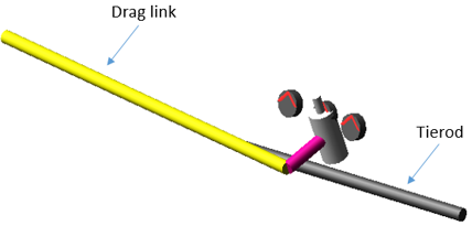
Figure 45 Haltenburger Simple Steering
Template name
_halt_simple_steering
Major role
Steering
Application
Suspension and full-vehicle assemblies
Description
This template is an extend version of the relay pitman simple steering template. It has an additional tierod part that connects drag link to steering arm. In this template, draglink to pitman arm, draglink outer, tierod inner and tierod outer locations are defined using the input communicators. These input communicators should have corresponding output communicators in the suspension templates.
Files referenced
Property files, hydraulic_steering_assist.ste or torsion_bar.ste and steering_compliance.ste are stored in the steer_assist.tbl of the acar_concept database. These defines the steering hydraulic assist force, torsion bar and steering compliance respectively.
Topology
The topology for Haltenburger steering mechanism is identical to the relay pitman simple steering template except for the joint added between tierod and the draglink.
Parameters
Refer to Relay and Pitman Simple Steering System.
Communicators
Refer to Relay and Pitman Simple Steering System.
In addition to above input communicators this template have:
cis_drag_link_to_pitman, cis_drag_link_outer, cis_tierod_inner and cis_tierod_outer.
Integral Link Suspension
Overview
This template represents an independent suspension with integral link and coil spring.
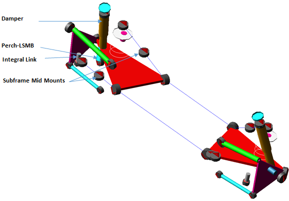
Figure 46 Integral Link Suspension
Template name
_integral_link
Major role
Suspension
Application
Suspension and full-vehicle assemblies
Description
The integral link suspension template represents a common independent rear suspension design.
It includes a lower control arm (LCA), upper control arm (UCA), subframe, integral link and tie rod.
You can select different topological options for the integral link. At the subsystem level, you can attach the integral link's upper point to the upright (wheel carrier), tie rod (toe link) or UCA (camber link) using a switch part. The UCA has two attachment options: subframe and frame, which is controlled using a switch part.
You can activate or deactivate the effect of Hub Compliance using the pvs_hub_compliance parameter variable.
You can change current mode of Subframe activity to None, Compliant or Kinematic. You can change number of Subframe MidMounts to none, Front Only, Rear Only or both.
You can toggle Perch - LSMB (Lower Shock Mounting Bracket).
Files referenced
Bushings, springs, dampers, bumpstop, and reboundstop property files.
Topology
The suspension includes a LCA, which connects to the subframe at two pivot points using bushings. At the outer ball joint, the LCA connects to a wheel carrier (upright). The integral link is positioned in front of the wheel spin axis. The integral link attaches the LCA and to the wheel carrier (upright), tierod (toe link) or UCA. The UCA and tierod connect the wheel carrier (upright) to the subframe or frame.
A spring acts between the LCA and frame. Bumpstops and reboundstops are used to limit wheel travel.
The joint: | Connects the part: | To the part: |
|---|---|---|
jolrev_spindle_to_upright | gel_spindle | gel_upright |
jolsph_hub_compliance | gel_spindle | gel_upright |
jolcon_drive_sft_otr | gel_drive_shaft | gel_spindle |
jolsph_upper_ball_joints | gel_uca_camber_adjuster | gel_upright |
jklsph_tierod_outer | gel_upright | gel_tierod_outer |
joltra_uca_split | gel_uca | gel_uca_camber_adjuster |
joltra_tierod_split | gel_tierod_outer | gel_tierod_inner |
jklcon_tierod_inner | gel_tierod_inner | mtl_tierod_to_steering |
jklrev_uca | gel_uca | swl_uca_attachment_options |
jklsph_integral_link_to_lca | gel_integral_link | gel_lca |
jolsph_integral_link_to_tierod | gel_integral_link | swl_integral_link_attachment_options |
jolcon_drive_sft_int_jt | gel_tripot | gel_drive_shaft |
joltra_tripot_to_differential | gel_tripot | mtl_tripot_to_differential |
jolhoo_upper_strut_to_body | gel_upper_strut | mtl_strut_to_body |
jolcyl_lwr_to_upper_strut | gel_lower_strut | gel_upper_strut |
jklrev_lca | gel_lca | ges_subframe |
jolhoo_lower_strut_to_lca | gel_lower_strut | gel_lca |
jklsph_lower_ball_joint | gel_upright | gel_lca |
Parameters
Toe and camber variables define the wheel spin axis, spindle part, and spindle geometry. The following table lists the parameters in the template.
The parameter: | Takes the value: | Its units are: | Integer |
|---|---|---|---|
phs_driveline | Integer | No units | 0 = Inactive, 1 = Active |
phs_kinematic_flag | Integer | No units | 0 = Inactive, 1 = Active |
pvs_subframe | Integer | No units | 0 = None, 1 = Compliant , 2 = Kinematic |
pvs_adjuster | Integer | No units | 0 = Inactive, 1 = Active |
ph[lr]_toe_adjuster | Real | mm | |
ph[lr]_camber_adjuster | Real | mm | |
pv[lr]_toe_angle | Real | Degrees | |
pv[lr]_camber_angle | Real | Degrees | |
pv[lr]_drive_shaft_offset | Real | mm | |
pvs_perch | Integer | No units | 0 = Inactive, 1 = Active |
pvs_hub_compliance | Integer | No units | 0 = Inactive, 1 = Active |
pvs_hub_compliance_offset | Integer | No units | |
pvs_number_of_bumpstops | Integer | No units | 0 = None, 1 = One, 2 = Two |
pvs_number_of_reboundstops | Integer | No units | 0 = None, 1 = One, 2 = Two |
Communicators
Mount parts provide connectivity from the template to body subsystems and the differential. Output Communicators publish toe, camber, steer axis, and wheel-center location information to the appropriate subsystems and the test rig. The following table lists the input and output communicators.
The communicator: | Belongs to the class: | Has the role: |
|---|---|---|
ci[lr]_ARB_pickup | location | inherit |
ci[lr]_spring_to_body | mount | inherit |
ci[lr]_strut_to_body | mount | inherit |
ci[lr]_tierod_to_steering | mount | inherit |
ci[lr]_tripot_to_differential | mount | inherit |
ci[lr]_uca_to_body | mount | inherit |
cis_subframe_to_body | mount | inherit |
co[lr]_arb_bushing_mount | mount | inherit |
co[lr]_camber_angle | parameter_real | inherit |
co[lr]_ride_height_ref | marker | inherit |
co[lr]_suspension_mount | mount | inherit |
co[lr]_suspension_upright | mount | inherit |
co[lr]_toe_angle | parameter_real | inherit |
co[lr]_tripot_to_differential | location | inherit |
co[lr]_wheel_center | location | inherit |
cos_suspension_parameters_ARRAY | array | inherit |
MacPherson Suspension
Overview
This MacPherson suspension template is a modified version of the standard MacPherson Suspension. In this template, the drive shafts are not modeled. If this suspension is intended to be used as a driven axle, you'll need to include in your full-vehicle assembly a template of major role "driveline".
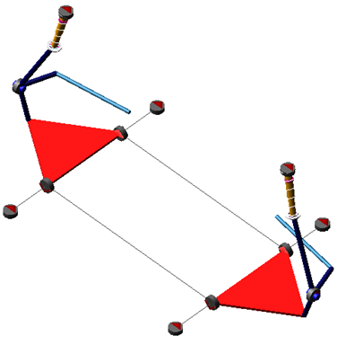
Figure 47 MacPherson Suspension
Template name
_macpherson
Major role
Suspension
Application
Suspension and full-vehicle assemblies
Description
Refer to the standard MacPherson Suspension.
MacPherson Advanced Suspension
Overview
This template is an enhanced version of the MacPherson Suspension in the shared Adams Car database.
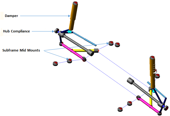
Figure 48 MacPherson Advanced Suspension
Template name
_macpherson_advanced
Major role
Suspension
Application
Suspension and full-vehicle assemblies
Description
This template is identical to the standard MacPherson Suspension template expect with the additions of lower control arm (LCA) configuration design option, top dual path mount design option and switch part options for spring, and bumpstop upper.
The LCA is modeled with four configuration options: single ball joint, dual ball joint, dual link with compression and dual link with tension strut. These configurations can be changed using the design options Lower Control Arm Configuration.
The top dual path mount option can be activated using the design option Top Dualpath Mount. You can also change spring, and bumpstop top attachment parts using their respective switch part options.
You can change current mode of Subframe activity to None, Compliant or Kinematic. You can change number of Subframe MidMounts to None, Front Only, Rear Only or Both.
Files referenced
Bushings, springs, dampers, bumpstop, and reboundstop property files.
Topology
The topology is identical to the MacPherson Suspension template except for the LCA configuration and Top Dualpath Mount design options.
The following table details the topologies for LCA configuration options.
Design Option | The joint: | Connects the part: | To the part: |
|---|---|---|---|
LCA Single Ball Joint Configuration 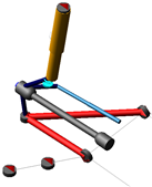 | jolrev_lca | gel_lower_control_arm | sws_subframe_attachment_options |
LCA Dual Ball Joint Configuration 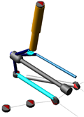 | jolhoo_lca_link_2_inner | gel_lower_control_arm | sws_subframe_attachment_option |
jolhoo_link_2_inner | gel_lca_link_2 | sws_subframe_attachment_options | |
jolsph_lca_link_2_balljoint | gel_lca_link_2 | gel_upright | |
LCA Dual Link with compression Configuration 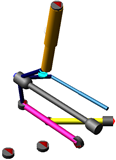 | jolcyl_lca_compression_inner | gel_lower_control_arm | sws_subframe_attachment_options |
jolsph_compression_inner | gel_lca_compression_bar | sws_subframe_attachment_options | |
jolhoo_compression_outer | gel_lower_control_arm | gel_lca_compression_bar | |
LCA Dual Link with Tension strut Configuration 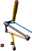 | jolsph_tension_inner | gel_lca_tension_strut | sws_subframe_attachment_options |
jolcyl_lca_tension_inner | gel_lower_control_arm | sws_subframe_attachment_options | |
jolhoo_tension_outer | gel_lower_control_arm | gel_lca_tension_strut | |
Hub Compliance Active | jolsph_hub_compliance | gel_spindle | gel_upright |
Hub Compliance Inactive | jolrev_spindle_upright | gel_spindle | gel_upright |
Parameters
The parameter below is additional to the MacPherson Suspension template.
The parameter: | Takes the value: | Its units are: | Description |
|---|---|---|---|
pvs_lower_control_arm_configuration | Integer | No units | 1 = Single Ball Joint, 2 = Dual Ball Joint, 3 = Dual Link with Compression, 4 = Dual Link with Tensions Strut |
phs_subframe | Integer | No units | 0 = None, 1 = Compliant , 2 = Kinematic |
pvs_subframe_midmounts | Integer | No units | 0 = None, 1 = Front Only, 2 = Rear Only, 3 = Both |
pvs_number_of_reboundstops | Integer | No units | 0 = None, 1 = One, 2 = Two |
pvs_number_of_bumpstops | Integer | No units | 0 = None, 1 = One, 2 = Two |
pvs_hub_compliance | Integer | No units | 0 = Inactive, 1 = Active |
pvs_top_dualpath_mount | Integer | No units | 0 = Inactive, 1 = Active |
Communicators
Refer to the standard MacPherson Suspension.
Multi-Link Suspension
Overview
This multi-link suspension template is a modified version of the standard Multi-Link Suspension. In this template, the drive shafts are not modeled. If this suspension is intended to be used as a driven axle, you'll need to include in your full-vehicle assembly a template of major role "driveline".
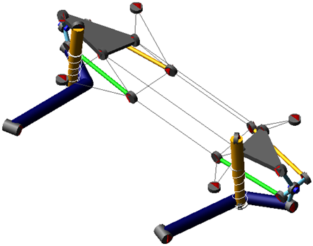
Figure 49 Multi-Link Suspension
Template name
_multi_link
Major role
Suspension
Application
Suspension and full-vehicle assemblies
Description
Refer to the standard Multi-Link Suspension.
Parallel-Link Steering System
Overview
This parallel-link steering system template is a modification of the standard Parallel-Link Steering System.
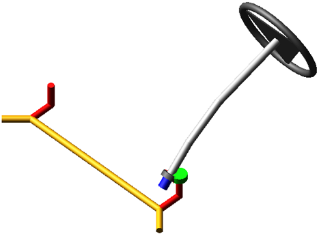
Figure 50 Parallel-Link Steering
Template name
_parallel_link_steering
Major role
Steering
Application
Suspension and full-vehicle assemblies
Description
A recirculating ball steering gear transmits motion from the steering wheel to the pitman arm. The pitman arm rotates to impart motion to the center link and idler arm. The translation of the center link pulls and pushes the tie rods to steer the wheels.
Files referenced
Steering assist property file. The default property file is mdi_steer_assis.ste, stored in the steer_assist.tbl directory of the shared Adams Car database.
Topology
The recirculating ball steering gear consists of three major parts:
■Ball screw
■Rack
■Sector
The steering wheel rotates the steering input shaft. A torsion bar attaches the steering input shaft to a ball screw. The ball screw imparts translational motion to the steering gear through a coupler. The steering gear, in turns, rotates the sector through a coupler, which is connected directly to the pitman arm shaft.
The following table maps the topology of the template.
The joint: | Connects the part: | To the part: |
|---|---|---|
jo[lr]sph_centerlink_arm | ges_center_link | ge[lr]_arm |
joscyl_steering_wheel | ges_steering_column | mts_steering_column_to_body |
josfix_steering_gear_housing | ges_steering_gear_housing | swl_steering_gear_mount |
josfix_steering_wheel_to_column | ges_steering_wheel | ges_steering_column |
josper_centerlink_pitman_arm | ges_center_link | gel_arm |
josrev_ball_screw_steering_gear | ges_ball_screw | ges_steering_gear_housing |
josrev_idler_arm_to_body | ger_arm | swr_steering_gear_mount |
josrev_input_shaft_steering_gear | ges_input_shaft | ges_steering_gear_housing |
josrev_pitman_arm_to_body | gel_arm | swl_steering_gear_mount |
jostra_rack_steering_gear | ges_rack | ges_steering_gear_housing |
josuni_column_intermediate | ges_steering_column | ges_intermediate_shaft |
josuni_intermediate_shaftinput | ges_intermediate_shaft | ges_input_shaft |
gksred_ball_screw_input_shaft_lock | josrev_ball_screw_steering_gear | josrev_input_shaft_steering_ gear |
grsred_ball_screw_rack | josrev_ball_screw_steering_gear | jostra_rack_steering_gear |
grsred_pitman_arm_rack | josrev_pitman_arm_steering_gear | jostra_rack_steering_gear |
Parameters
A parameter variable switches between kinematic and compliant mode, effectively locking out the torsion bar deflection.
Communicators
The following table lists the communicators in the template.
The communicator: | Belongs to the class: | Has the role: |
|---|---|---|
ci[lr]_steering_gear_to_body | mount | inherit |
ci[lr]_steering_gear_to_suspension_subframe | mount | inherit |
cis_steering_column_to_ body | mount | inherit |
co[lr]_tierod_to_steering | mount | front |
cos_max_rack_ displacement | parameter_real | inherit |
cos_max_rack_force | parameter_real | inherit |
cos_max_steering_angle | parameter_real | inherit |
cos_max_steering_torque | parameter_real | inherit |
cos_steering_rack_joint | joint_for_motion | inherit |
cos_steering_wheel_joint | joint_for_motion | inherit |
Note: | The parallel-link steering template contains a general spline, gss_steering_assist, which provides assist force as a function of the angular deflection of the input shaft relative to the ball screw. A switch part is also present. It allows you to explore two different topological solutions. You can rigidly connect the steering gear to the body or to the front suspension subframe. |
Powertrain Advanced
Overview
This Powertrain Advanced system is a modification of the Powertrain System in the Adams Car shared database. This system has also been included with two roll restrictors with option to connect roll restrictor to subframe or body and additional engine mount option.
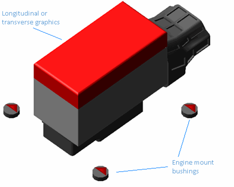
Figure 51 Powertrain Advanced System
Template name
_powertrain_advanced
Major role
Powertrain
Application
Full-vehicle assemblies
Description
Refer to the Powertrain System in the Adams Car shared database. The only difference is the addition of roll restrictor, additional engine mounts and engine orientation.
Using pvs_engine_orientation you can change orientation of engine graphics. You can set engine graphics orientation along transverse or longitudinal direction.
Parameters
The parameters are identical to the Powertrain System in the Adams Car shared database, with the additions as following:
The parameter: | Takes the value: | Its units are: | Integer |
|---|---|---|---|
phs_engine_mounts | Integer | No units | 2 = two engine mounts, 3 = three engine mounts 4 = four engine mounts 5 = five engine mounts |
pvs_roll_restrictor | Integer | No units | 0 = Inactive, 1 = Active |
pvs_roll_restrictor_2 (second roll restrictor) | Integer | No units | 0 = Inactive, 1 = Active |
pvs_engine_orientation | Integer | No units | 0 = Transverse, 1 = Longitudinal |
Powertrain Simple Traction
Overview
The powertrain simple traction template provides torque directly to the four wheels. The proportion of the torque applied to front and rear wheels will depend on drive bias (pvs_drive_torque_bias_front) ratio.
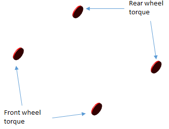
Figure 52 Powertrain Simple Traction System
Template name
_powertrain_simple_traction
Major role
Powertrain
Application
Full-vehicle assemblies
Description
The powertrain simple traction system template represents a simple model of traction system. It applies a rotational torque directly to the wheels.
Files referenced
None.
Topology
The simple traction powertrain template contains very simple topological information because it is a functional representation of the powertrain. A rotational SFORCE is applied between suspension upright and wheel.
Parameters
The toe and camber values that the suspension subsystem publishes define the spin axis orientation. If adjustable forces are present in the model, spin axis orientation will be defined during runtime based on the specified alignment values. In addition, the driving torque is expressed as a function of a number of parameters. The drive ratio is set by pvs_drive_torque_bias_front, when set to 0.5, it apply torque to front and rear wheels. When set to 0, it drives rear wheels. When set to 1, it drives front wheels.
The following table lists the parameters in the template.
The parameter: | Takes the value: | Its units are: |
|---|---|---|
pvs_drive_torque_bias_front | Real | No units |
phs_throttle_I_gain* | Real | No units |
phs_throttle_P_gain* | Real | No units |
phs_throttle_scale* | Real | No units |
Limitations
The powertrain simple traction template is a simple model of a traction powertrain system. It does not model the complex interaction between engine and wheels.
Communicators
Mount parts provide the connectivity between the template and suspension subsystems. Input Communicators receive information about the toe and camber suspension orientation and the wheel-center location. Input to the powertrain system is throttle demand.
The following table lists the communicators in the template.
The communicator: | Belongs to the class: | Has the role: | Matching name: |
|---|---|---|---|
ci[lr]_front_traction_to_wheel | Mount | front | rotor_to_wheel |
ci[lr]_rear_traction_to_wheel | Mount | rear | rotor_to_wheel |
ci[lr]_front_suspension_upright | Mount | front | suspension_upright |
ci[lr]_rear_suspension_upright | Mount | rear | suspension_upright |
ci[lr]_front_tire_force | Force | front | tire_force |
ci[lr]_rear_tire_force | Force | rear | tire_force |
ci[lr]_front_camber_angle | Parameter Real | front | camber_angle |
ci[lr]_rear_camber_angle | Parameter Real | rear | camber_angle |
ci[lr]_front_toe_angle | Parameter Real | front | toe_angle |
ci[lr]_rear_toe_angle | Parameter Real | rear | toe_angle |
ci[lr]_front_wheel_center | Location | front | wheel_center |
ci[lr]_rear_wheel_center | Location | rear | wheel_center |
cis_throttle_demand | Solver Variable | inherit | throttle_demand |
cis_sse_diff1 | Differential Equation | inherit | sse_diff1 |
cis_desired_velocity | Solver Variable | inherit | desired_velocity |
cis_driver_reference | Marker | inherit | driver_reference |
cos_drive_torque_bias_front | Parameter Real | any | drive_torque_bias_front |
cos_transmission_input_omega | Solver Variable | inherit | transmission_input_omega |
cos_engine_speed | Solver Variable | inherit | engine_speed |
cos_max_engine_driving_torque | Solver Variable | inherit | engine_maximum_driving_torque |
Quad-Link Axle Advanced Suspension
The quad-link axle advanced suspension template is an enhanced version of the standard Quad-Link Axle Suspension.
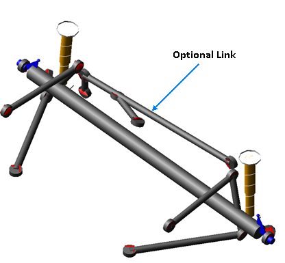
Figure 53 Quad-Link Axle Advanced Suspension
Template name
_quad_link_advanced
Major role
Suspension
Application
Suspension and full-vehicle assemblies
Description
This quad-link axle advanced suspension template is identical to the quad-link template except for the addition of configurations (design options) for four link control arm and four link type.
The control arms are modeled with five options: UCA Inactive, UCA Left and Right, UCA Left only, UCA Right only and LCA Single piece. These configurations can be changed using the design options Four Link Control Arm Configurations.
The four link type has provided with four options: Basic, Panhard rod, Watts Link and Multi-Link configurations. These configurations can be changed using the design options Four Link Type.
Files referenced
Bushing, spring, and damper property files
Topology
The topology is identical to the Quad-Link Axle Suspension template, except for the addition of four link control arm configuration and four link type.
You can set subsystems based on this template to Steerable axle or Non-Steerable axle using design option Steerable Axle.
The following table maps the additional and modified topology of this template:
The joint: | Connects the part: | To the part: |
|---|---|---|
joshoo_right_knuckle_tierod_hooke | ges_tierod | ger_knuckle |
jossph_tierod_knuckle | ges_tierod | ger_knuckle |
Parameters
The quad-link axle advanced suspension template includes additional parameter variables beside those described in the Quad-Link Axle Suspension template.
The parameter: | Takes the value: | Its units are: | Integer |
|---|---|---|---|
phs_kinematic_flag | Integer | No units | 0 = Inactive, 1 = Active |
pvs_hub_compliance | Integer | No units | 0 = Inactive, 1 = Active |
pvs_four_link_control_arm_configurations | Integer | No units | 0 = UCA Inactive 1 = UCA Left and Right 2 = UCA Left Only, 3 = UCA Right Only, 4 = LCA Single Piece |
pvs_four_link_type | Integer | No units | 0 = Basic, 1 = Panhard Rod 2 = Watts Link 3 = Multi-link |
pvs_steerable_axle | Integer | No units | 0 = Inactive, 1 = Active |
pvs_number_of_bumpstops | Integer | No units | 0 = None, 1 = Bumpstop One Only |
pvs_number_of_reboundstops | Integer | No units | 0 = None, 1 = Reboundstop One Only |
pv[lr]_toe_angle | Real | Degrees | |
pv[lr]_camber_angle | Real | Degrees | |
Pv[lr]_hub_compliance_offset | Real | mm |
Communicators
The following table lists the additional input and output communicators beside those described in the Quad-Link Axle Suspension template.
The communicator: | Belongs to the class: | Has the role: |
|---|---|---|
cis_tierod_steering | mount | inherit |
cis_panhard_to_body | mount | inherit |
cos_draglink_connection | mount | inherit |
Rack and Pinion Steering System
Overview
This rack and pinion steering system is a modification of the standard Rack and Pinion Steering System.
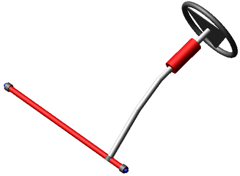
Figure 54 Rack and Pinion Steering System
Template name
_rack_pinion_steering
Major role
Steering
Application
Suspension and full-vehicle assemblies
Description
Refer to the standard Rack and Pinion Steering System. The main difference is that the Hooke joints have been replaced with constant velocity joints.
Rack and Pinion Advanced Steering System
Overview
The rack and pinion advanced steering template is an enhanced version of the standard Rack and Pinion Steering System.

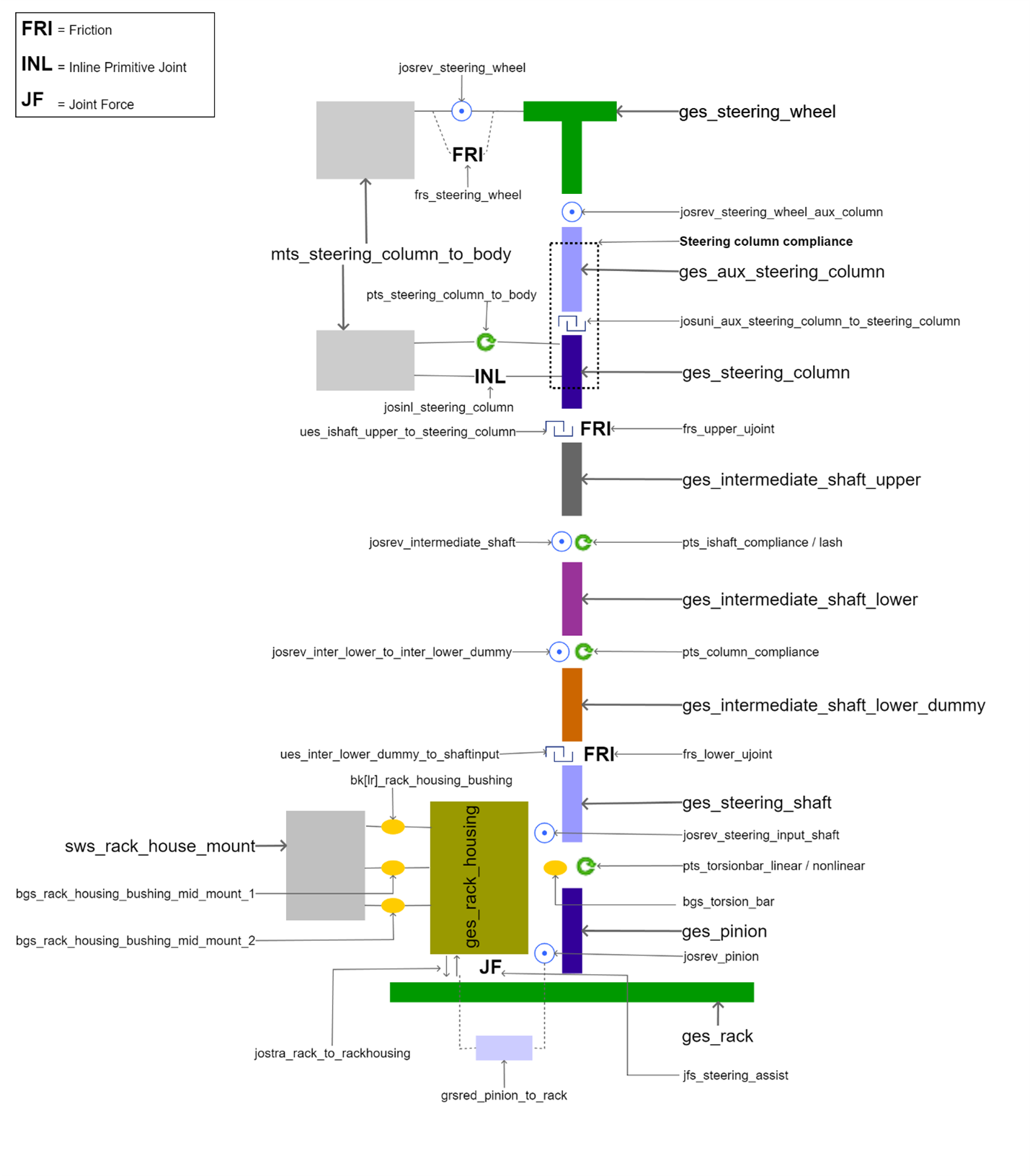
Template name
_rack_pinion_steering_advanced
Major role
Steering
Application
Suspension and full-vehicle assemblies
Description
This template is identical to the Rack and Pinion Steering System except for the following:
■Various steering compliances
■New Torsional bar methods.
■Friction on steering wheel and universal joints
■Rack housing mid mounts
■Hook joints are replaced by hooke joints with angle UDE
■Tilt universal joint to support tilt adjustment of upper steering column shafts
In this template, 'steering column to body', 'steering column', 'intermediate-shaft' or 'lash', and 'column' compliances are added into the template. These compliances can be activated or deactivated individually using respective design options. For more information, see Advanced Steering Design Options.
The torsion bar method can be changed using design options Torsion Bar Method. The steering assist method can be changed using design options Steering Assist and Boost Type.
The friction is modeled for joints like revolute joint between steering wheel and body, upper and lower universal joints. These frictions can be activated or deactivated using respective design options.
The optional two mounts has been added for rack house mountings, it can be activated by using design options Rack Housing Midmount.
Files referenced
Property files, hydraulic_steering_assist.ste or electric_steering_assist.ste or torsion_bar.ste and steering_compliance.ste are stored in the steer_assist.tbl of the acar_concept database. These defines the steering hydraulic assist force, electric steering assist, torsion bar and steering compliance respectively.
Topology
The topology is identical to the Rack and Pinion Steering System except for the hook's joints are replaced by hooke joint with angle UDE, and addition of tilt universal joint, rack housing mid mounts, various steering compliances, frictions and torsional bar methods.
The joint: | Connects the part: | To the part: |
|---|---|---|
josinl_steering_column | ges_steering_column | mts_steering_column_to_body |
josrev_dummy_to_steering_column | ges_steering_column_compliance_dummy | ges_steering_column |
josrev_intermediate_shaft_upper_to_lower | ges_intermediate_shaft_upper | ges_intermediate_shaft_lower |
josrev_ishaft_lower_to_ishaft_lower_dummy | ges_intermediate_shaft_lower | ges_intermediate_shaft_lower_dummy |
josrev_steering_wheel_to_aux_column | ges_steering_wheel | ges_aux_steering_column |
josuni_aux_steering_column_to_dummy | ges_aux_steering_column | ges_steering_column_compliance_dummy |
josuni_aux_steering_column_to_steering_column | ges_aux_steering_column | ges_steering_column |
ues_ishaft_upper_to_steering_column | ges_intermediate_shaft_upper | ges_steering_column |
ues_steering_shaft_to_ishaft_lower_dummy | ges_steering_shaft | ges_intermediate_shaft_lower_dummy |
Parameters
These integer parameter variables allow you to activate and deactivate the various Advanced Steering Design Options. Only those parameters additional to the Rack and Pinion Steering System template are listed below.
The parameter: | Takes the value: | Its units are: | Description |
|---|---|---|---|
pvs_column_compliance | Integer | No units | 0= None, 1=Linear, 2=Nonlinear |
pvs_intermediate_shaft_compliance | Integer | No units | 0= None, 1=Lash, 2= Linear, 3= Nonlinear |
pvs_lower_u_joint_friction | Integer | No units | 0 = Inactive, 1 = Active |
pvs_rack_housing_mid_mount | Integer | No units | 0 = None 1 = Mid-Mount One, 2 = Mid-Mount Both |
pvs_steering_assist | Integer | No units | 0 = None, 1 = Hydraulic, 2 = EPAS Column, 3 = EPAS Rack Simple, 4 = EPAS Rack Comples, 5 = EPAS Pinion, 6 = EPAS Second Pinion |
pvs_steering_column_body_compliance | Integer | No units | 0 = Inactive, 1 = Active |
pvs_steering_column_compliance | Integer | No units | 0= None, 1=Linear, 2=Nonlinear |
pvs_steering_column_to_body_damping | Real | torsion_damping | Column to Body Viscous Damping |
pvs_steering_wheel_friction | Integer | No units | 0 = Inactive, 1 = Active |
pvs_torsion_bar_method | Integer | No units | 1=Linear, 2=Linear Using Stop Angle, 3=Geometry, 4=Geometry Using Stop Angle, 5=Nonlinear |
pvs_u_joint_phase_angle_1 | Real | angle | U-Joint phasing angle 1 |
pvs_u_joint_phase_angle_2 | Real | angle | U-Joint phasing angle 2 |
pvs_u_joint_phasing | Integer | No units | 0 = Inactive, 1 = Active |
pvs_upper_u_joint_friction | Integer | No units | 0 = Inactive, 1 = Active |
Communicators
Refer to the Rack and Pinion Steering System.
Rack and Pinion Tilt 3 Universal Joint Steering System
Overview
The rack and pinion tilt 3 universal joint steering template is an enhanced version of the standard Rack and Pinion Steering System and Rack and Pinion Advanced Steering System.
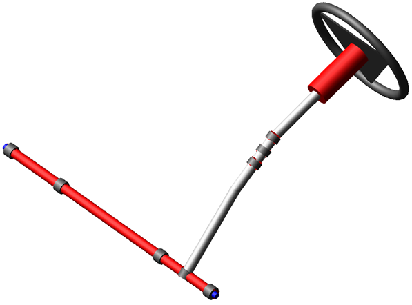
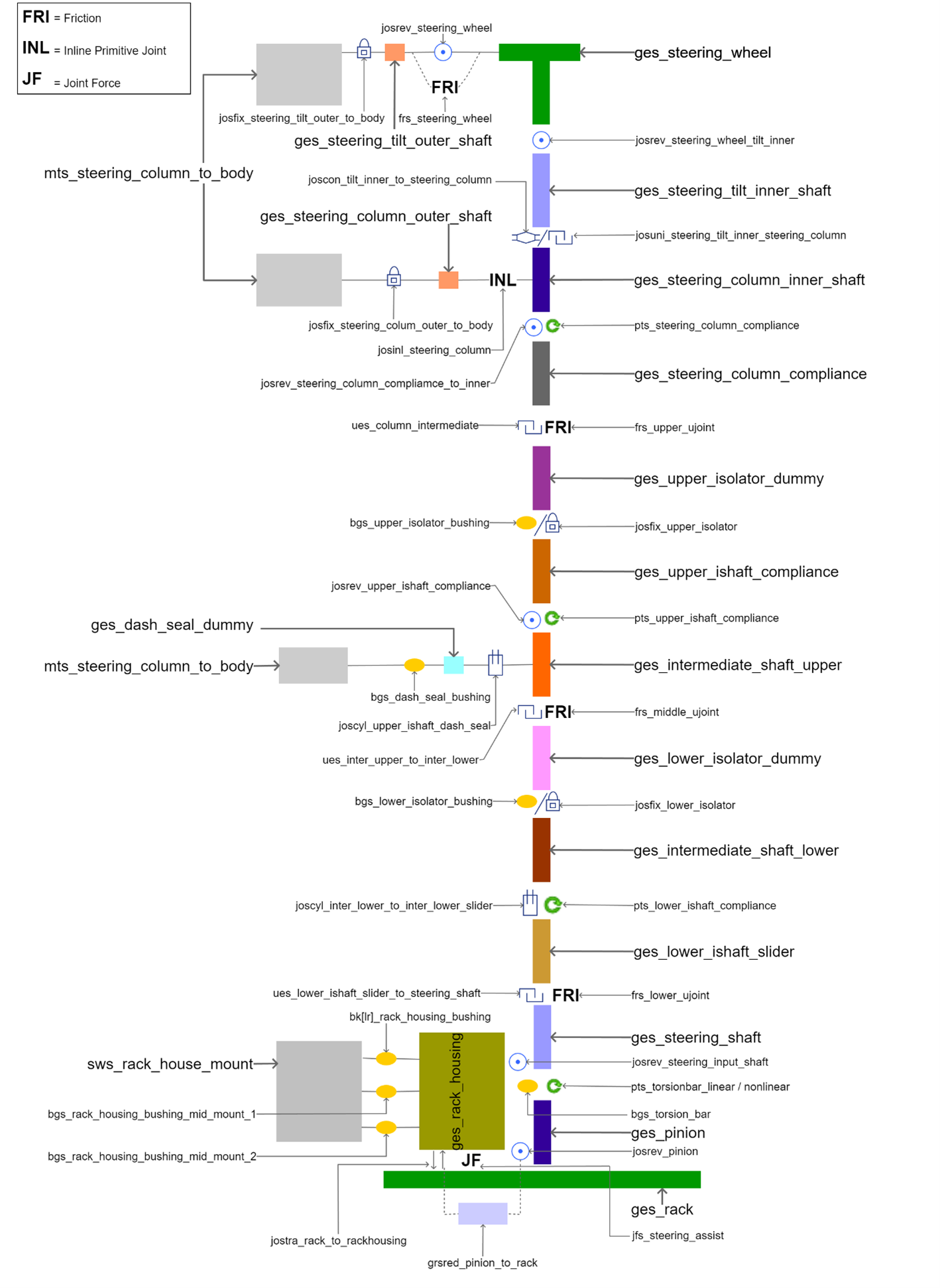
Template name
_rack_pinion_tilt_3ujoint_steering
Major role
Steering
Application
Suspension and full-vehicle assemblies
Description
This template have additional hooke joint with angle and different design options than that of Rack and Pinion Advanced Steering System.
The compliance for intermediate shaft is split into upper and lower intermediate shaft compliance. Also, upper and lower isolators are provided.
The dash seal compliance option is provided in this template. It can be attached to upper, lower or steering shaft using "dash_seal_attach" switch part.
The value of each of this design options can be set using respective parameter variables.
For more information, see Advanced Steering Design Options.
Files referenced
Property files, hydraulic_steering_assist.ste or electric_steering_assist.ste or torsion_bar.ste and steering_compliance.ste are stored in the steer_assist.tbl of the acar_concept database. These defines the steering hydraulic assist force, electric steering assist, torsion bar and steering compliance respectively.
Topology
The steering tilt inner shaft connects with steering column inner shaft either with constant velocity joint or universal joint as per choice set for the design options Steering Column Tilt Joint Type. Also, bushings are activated if the design options upper isolator or lower isolator are active, otherwise fixed joint is used to represent single link.
The dash seal dummy is connected with switch part which allows you to switch the connected part to either intermediate shaft upper, intermediate shaft lower or steering shaft. In this template, the order of the parts list given to the switch part (sws_dash_seal_attach) is important.
The detailed topology is defined in following table:
The joint: | The joint: | To the part: |
|---|---|---|
joscon_tilt_inner_to_steering_column | ges_steering_tilt_inner_shaft | ges_steering_column_inner_shaft |
joscyl_ishaft_lower_to_ishaft_lower_slider | ges_intermediate_shaft_lower | ges_ishaft_lower_slider |
joscyl_upper_ishaft_dash_seal | sws_dash_seal_attach | ges_dash_seal_dummy |
josfix_dash_seal_to_body | ges_dash_seal_dummy | mts_steering_column_to_body |
josfix_isolator_upper | ges_isolator_upper_dummy | ges_ishaft_upper_compliance |
josfix_lower_isolator | ges_isolator_lower_dummy | ges_intermediate_shaft_lower |
josfix_steering_colum_outer_shaft_to_body | ges_steering_column_outer_shaft | mts_steering_column_to_body |
josfix_steering_tilt_outer_to_body | ges_steering_tilt_outer_shaft | mts_steering_column_to_body |
josinl_steering_column | ges_steering_column_outer_shaft | ges_steering_column_inner_shaft |
josrev_ishaft_upper_compliance | ges_intermediate_shaft_upper | ges_ishaft_upper_compliance |
josrev_steering_column_compliamce_to_inner_shaft | ges_steering_column_compliance | ges_steering_column_inner_shaft |
josrev_steering_wheel | ges_steering_wheel | ges_steering_tilt_outer_shaft |
josrev_steering_wheel_to_tilt_inner_shaft | ges_steering_wheel | ges_steering_tilt_inner_shaft |
ues_column_intermediate | ges_isolator_upper_dummy | ges_steering_column_compliance |
ues_ishaft_lower_slider_to_steering_shaft | ges_ishaft_lower_slider | ges_steering_shaft |
ues_ishaft_upper_to_isolator_lower | ges_intermediate_shaft_upper | ges_isolator_lower_dummy |
josuni_steering_tilt_to_steering_column | ges_steering_tilt_inner_shaft | ges_steering_column_inner_shaft |
Parameters
These integer parameter variables allow you to activate and deactivate the various Advanced Steering Design Options. Only those parameters additional to the Rack and Pinion Steering System and Rack and Pinion Advanced Steering System template are listed below.
The parameter: | Takes the value: | Its units are: | Description |
|---|---|---|---|
pvs_column_tilt_joint | Integer | No units | 1 = Constant velocity, 2 = Universal |
pvs_dash_seal_compliance | Integer | No units | 0 = Inactive, 1 = Active |
pvs_dash_seal_friction | Integer | No units | 0 = Inactive, 1 = Active |
pvs_lower_intermediate_shaft_compliance | Integer | No units | 0= Inactive, 1=Linear, 2=Nonlinear |
pvs_isolator_lower | Integer | No units | 0 = Inactive, 1 = Active |
pvs_middle_u_joint_friction | Integer | No units | 0 = Inactive, 1 = Active |
pvs_upper_intermediate_shaft_compliance | Integer | No units | 0= Inactive, 1=Linear, 2=Nonlinear |
pvs_isolator_upper | Integer | No units | 0 = Inactive, 1 = Active |
pvs_u_joint_phase_angle_3 | Real | angle | U-Joint phasing angle 3 |
Communicators
Refer to the Rack and Pinion Steering System.
Rack and Pinion Tilt Bracket Steering System
Overview
The rack and pinion tilt bracket steering template is an enhanced version of the standard Rack and Pinion Advanced Steering System.
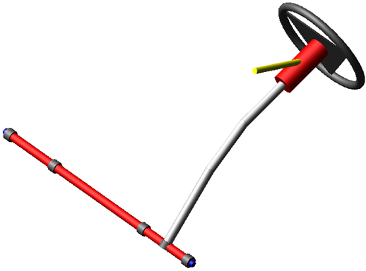
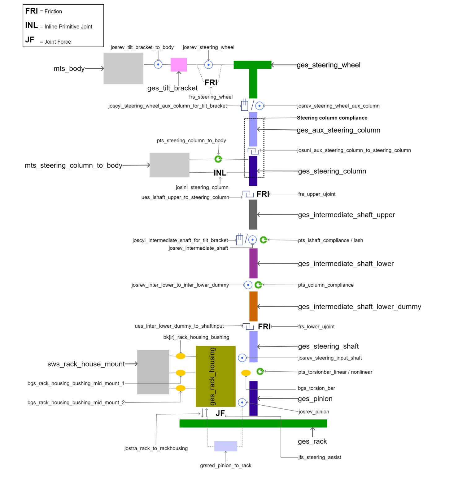
Template name
_rack_pinion_tilt_bracket_steering
Major role
Steering
Application
Suspension and full-vehicle assemblies
Description
This template is identical to the Rack and Pinion Advanced Steering System template except for the following:
■Tilt bracket part with revolute joint and its motion
■Additional cylindrical joint between steering wheel and auxiliary steering column
■Additional cylindrical joint between intermediate shaft lower and intermediate shaft upper
■Additional design options like "Tilt Bracket Slider Location" and "Tilt Bracket Angle"
■Activity of Additional cylindrical joints depends on choice of the parameter variable pvs_tilt_bracket_slider_location.
The design options Tilt Bracket Slider Location is used to set slider location either at the intermediate or upper steering column shaft to allow articulation of the column during tilt adjustment.
The parameter variable 'pvs_tilt_bracket_angle' is used to set angle of Tilt Bracket to Body Adjustment Angle during runtime.
This template contains compliances as per template Rack and Pinion Advanced Steering System like 'steering column to body', 'steering column', 'intermediate shaft' or 'lash' and 'column' compliances. These compliances can be activated or deactivated individually using respective design options. For more information, see Advanced Steering Design Options.
Files referenced
Property files, hydraulic_steering_assist.ste or electric_steering_assist.ste or torsion_bar.ste and steering_compliance.ste are stored in the steer_assist.tbl of the acar_concept database. These defines the steering hydraulic assist force, electric steering assist, torsion bar and steering compliance respectively.
Topology
The topology is identical to the Rack and Pinion Advanced Steering System template except for additional cylindrical joints
The joint: | Connects the part: | To the part: |
|---|---|---|
joscyl_intermediate_shaft_for_tilt_bracket | ges_intermediate_shaft_upper | ges_intermediate_shaft_lower |
joscyl_steering_wheel_aux_column_for_tilt_bracket | ges_steering_wheel | ges_aux_steering_column |
Parameters
These integer parameter variables allow you to activate and deactivate the various Advanced Steering Design Options. Only those parameters additional to the Rack and Pinion Advanced Steering System template are listed below.
The parameter: | Takes the value: | Its units are: | Description |
|---|---|---|---|
pvs_tilt_bracket_angle | Real | Angle | Tilt Bracket to Body Adjustment Angle |
phs_tilt_bracket_slider_location | Integer | No units | 1= Upper Shaft, 2= Intermediate Shaft |
Communicators
Refer to the Rack and Pinion Advanced Steering System.
Rack and Pinion Simple four Wheel Steering System
Overview
The rack and pinion simple four wheel steering template is an modified version of the standard Rack and Pinion Advanced Steering System. In which steering column is simplified and rear steer mechanism is added.
Figure 55 Rack and Pinion Simple four Wheel Steering
Template name
_rack_pinion_steering_simple_four_steer
Major role
Steering
Application
Suspension and full-vehicle assemblies
Description
This template is modified version of the Rack and Pinion Advanced Steering System template. In this template, steering column is simplified. There is no geometry and hardpoints to define the steering column profile. It has steering wheel, auxiliary steering column and intermediate shaft part defined at a single location. Also there is rear steering mechanism added.
To model only a front-steerable steering, you may turn off the rear steering components by setting the parameter variable pvs_rear_steer to 0.
Files referenced
Property files, hydraulic_steering_assist.ste or torsion_bar.ste and steering_compliance.ste are stored in the steer_assist.tbl of the acar_concept database. These defines the steering hydraulic assist force, torsion bar and steering compliance respectively.
Topology
The topology for rack and pinion simple four wheel steering mechanism is identical to the Rack and Pinion Advanced Steering System template except, rear steering mechanism.
The joint: | Connects the part: | To the part: |
|---|---|---|
jostra_rearsteer_rack_to_rackhouse | ges_rearsteer_rack | ges_rearsteer_rack_housing |
josrev_rear_actuator_to_housing | ges_rear_steering_actuator | ges_rearsteer_rack_housing |
Parameters
Only those parameters additional to the Rack and Pinion Advanced Steering System template are listed below.
The parameter: | Takes the value: | Its units are: | Description |
|---|---|---|---|
pvs_rear_steer_method | Integer | No units | 1 = In-Phase, 2 = Out-Phase, 3 = Spline Input |
pvs_rear_steer | Integer | No units | 0 = Inactive, 1 = Active |
pvs_re_fr_style | Integer | No units | |
pvs_re_fr_ang | Integer | No units | |
pvs_re_fr_rat_1 | Integer | No units | |
pvs_frt_rear_coupler_ratio | Real | No units | |
pvs_steer_delta | Real | No units | |
pvs_max_speed_1 | Real | Velocity | |
pvs_min_speed_1 | Real | Velocity | |
pvs_active_1 | Real | No units | |
pvs_rear_central_spring_damping_ct | Real | Damping | |
pvs_rear_central_spring_stiffness_kt | Real | Stiffness | |
pvs_steering_accuarcy | Real | No units | |
pvs_rear_central_spring_preload | Real | Force |
Communicators
Only those Communicators additional to the Rack and Pinion Advanced Steering System template are listed below.
The communicator: | Belongs to the class: | Has the role: |
|---|---|---|
cil_rearsteer_tierod_inner_loc | location | rear |
cil_wheel_center_marker_rear | marker | rear |
cil_kingpin_marker_rear | marker | rear |
cil_rearsteer_rack_to_axle | mount | rear |
cil_wheel_center_front_loc | location | front |
cil_body_ref | mount | inherit |
cis_steering_wheel_loc | location | front |
cis_steering_wheel | mount | front |
cis_body_at_steering_wheel_ref | mount | inherit |
col_rearsteer_tierod_inner | mount | rear |
cos_front_to_rear_coupler | joint for motion | rear |
cos_pseudo_velocity | solver variable | inherit |
Relay and Pitman Advanced Steering System
Overview
The relay and pitman advanced steering template is an modified version of the standard Rack and Pinion Advanced Steering System in which steering column is kept as it is and rack and pinion mechanism is replaced by relay rod mechanism and also have an options to activate pitman arm.
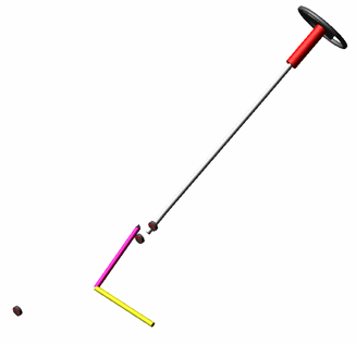
Figure 56 Relay Rod Advanced Steering
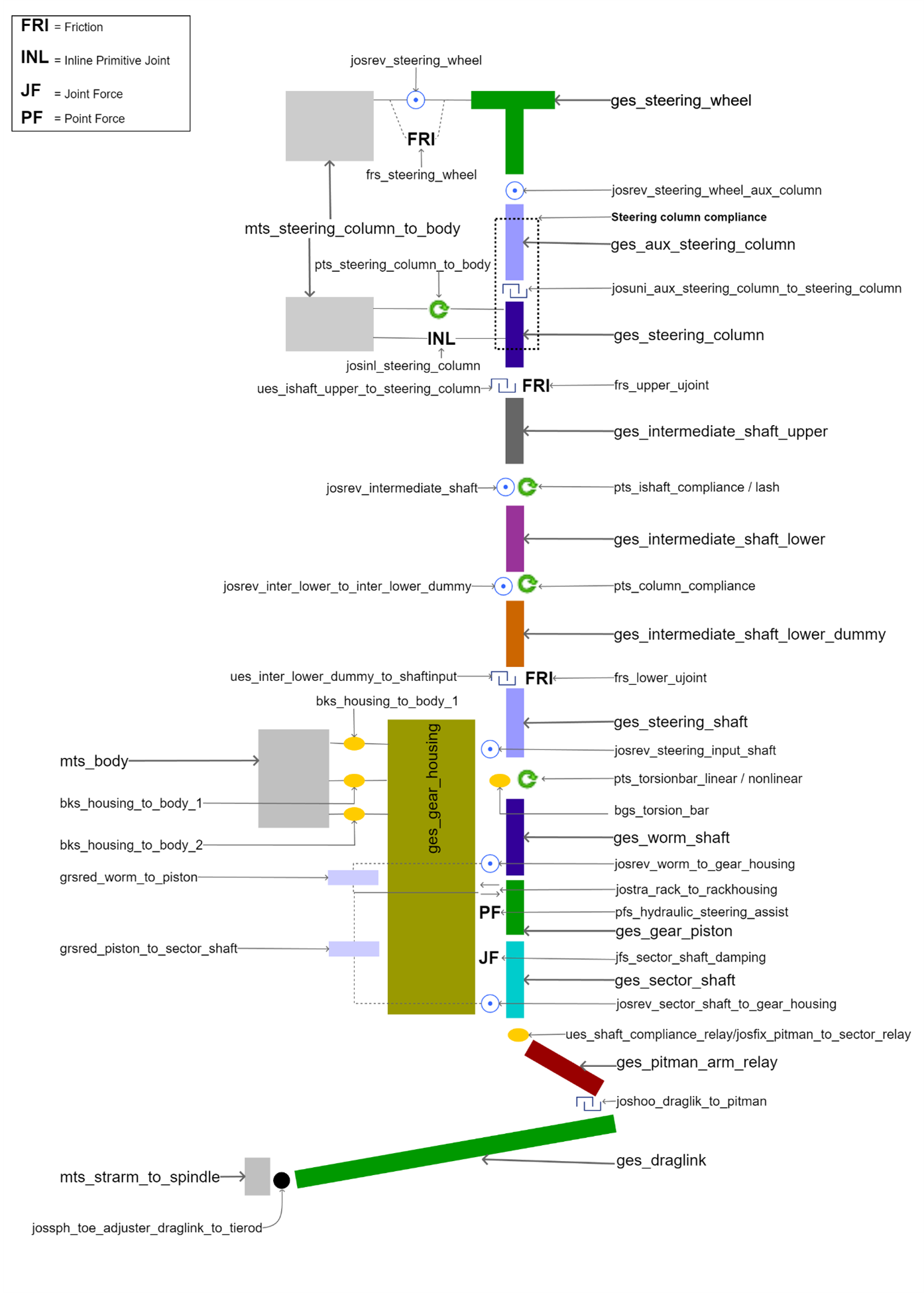
Figure 57 Relay Rod Advanced Steering Construction
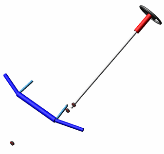
Figure 58 Pitman Arm Advanced Steering
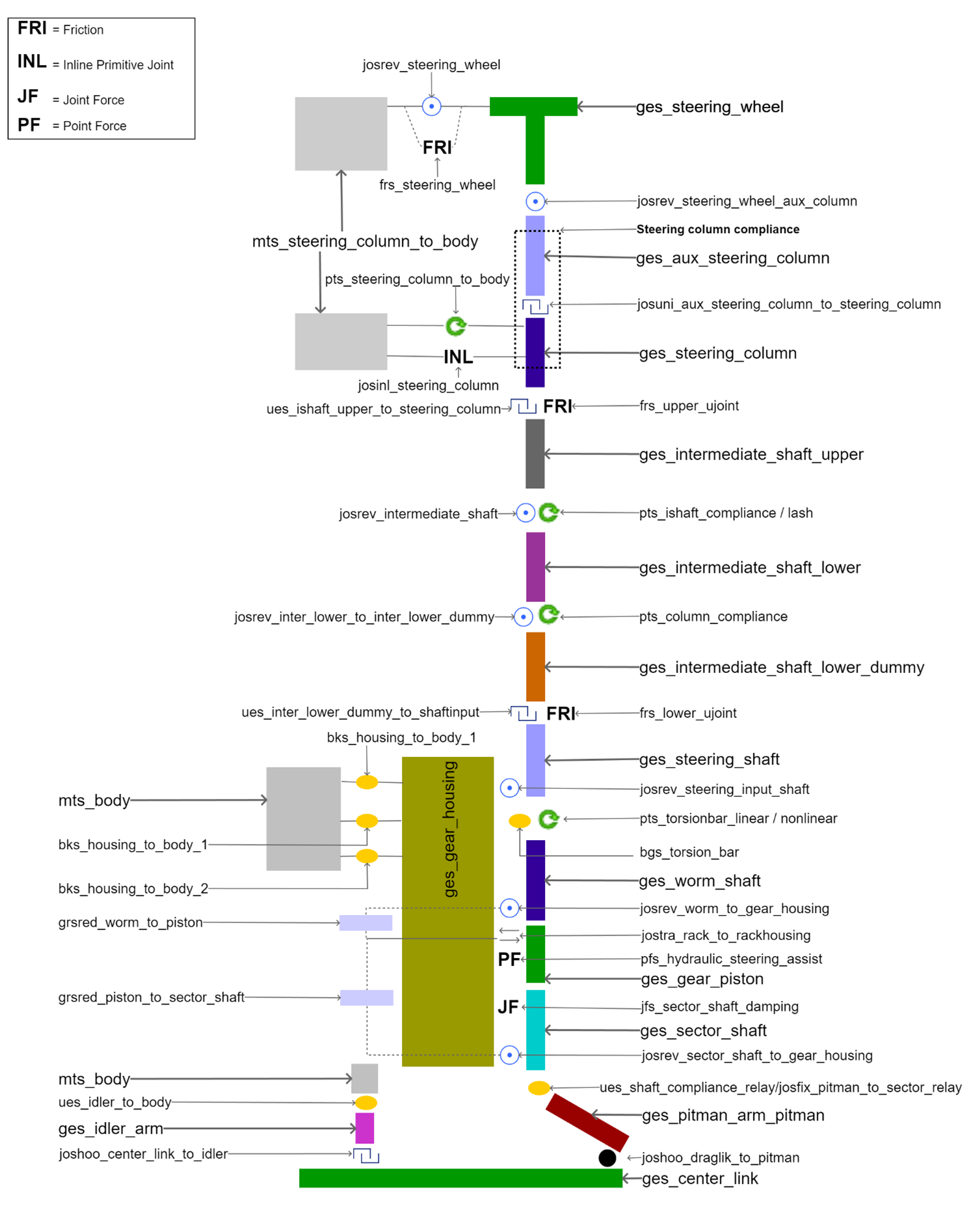
Figure 59 Pitman Arm Advanced Steering Construction
Template name
_relay_pitman_advanced
Major role
Steering
Application
Suspension and full-vehicle assemblies
Description
This template is modified version of the Rack and Pinion Advanced Steering System template. In this template, the rack and pinion mechanism is replaced by the relay rod mechanism and pitman arm mechanism is added which user can switch by using design option. There is no EPAS assist modeled in this template.
In this template, additional friction like "gear input friction", "piston friction", "sector shaft friction" for relay rod and "idler arm friction" for pitman arm configuration has been included. These frictional forces can be activated or deactivated using respective parameter variable.
The hydraulic steering assist has been added with two more option "velocity dependent" and "velocity and electric dependent".
Files referenced
Property files, hydraulic_steering_assist.ste or torsion_bar.ste and steering_compliance.ste are stored in the steer_assist.tbl of the acar_concept database. These defines the steering hydraulic assist force, torsion bar and steering compliance respectively.
Topology
The topology is identical to the Rack and Pinion Advanced Steering System template except for the joints added for the relay rod and pitman arm mechanism.
The joint: | Connects the part: | To the part: |
|---|---|---|
josrev_housing_to_input_shaft | ges_steering_shaft | ges_gear_housing |
josfix_worm_to_input_shaft | ges_worm_shaft | ges_steering_shaft |
jksfix_housing_to_body | ges_gear_housing | mts_body |
josrev_sector_shaft_to_gear_housing | ges_sector_shaft | ges_gear_housing |
josrev_worm_to_gear_housing | ges_worm_shaft | ges_gear_housing |
jostra_piston_to_gear_housing | ges_gear_piston | ges_gear_housing |
Topology for Relay Rod Mechanism
Design Option | The joint: | Connects the part: | To the part: |
|---|---|---|---|
Relay 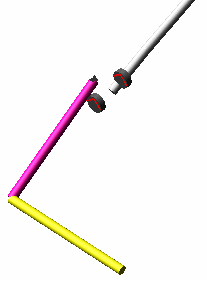 | josfix_pitman_to_sector_relay | ges_pitman_arm_relay | ges_sector_shaft |
joshoo_draglik_to_pitman | ges_draglink | ges_pitman_arm_relay | |
jostra_draglink_to_toe_adjuster | ges_draglink | ges_toe_adjuster_draglink | |
jossph_toe_adjuster_draglink_to_tierod | ges_toe_adjuster_draglink | mts_strarm_to_spindle | |
Pitman 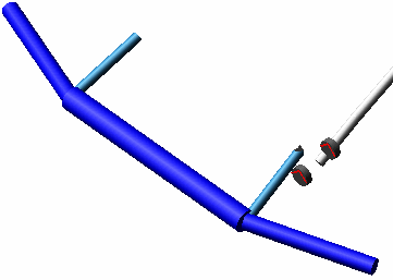 | josfix_pitman_to_sector_pitman | ges_pitman_arm_pitman | ges_sector_shaft |
jossph_center_link_to_pitman | ges_center_link | ges_pitman_arm_pitman | |
joshoo_center_link_to_idler | ges_center_link | ges_idler_arm | |
ues_idler_to_body | ges_idler_arm | sws_idle_connection_attachment_options |
Parameters
These integer parameter variables allow you to activate and deactivate the various Advanced Steering Design Options. Only those parameters additional to the Rack and Pinion Advanced Steering System template are listed below.
The parameter: | Takes the value: | Its units are: | Description |
|---|---|---|---|
pvs_gear_input_friction | Integer | No units | 0= Inactive, 1=Active |
pvs_sector_shaft_friction | Integer | No units | 0= Inactive, 1=Active |
pvs_piston_friction | Integer | No units | 0= Inactive, 1=Active |
pvs_idler_arm_friction | Integer | No units | 0= Inactive, 1=Active |
pvs_shaft_compliance | Integer | No units | 0= Off, 1 = On |
pvs_worm_lead | Integer | No units | -1 = Left hand lead, 1 = Right hand lead |
pvs_steering_gear_type | Integer | No units | 1=Relay, 2=Pitman |
pvs_shaft_compliance_stiffness | Real | torsion_stiffness | Torsional stiffness for sector shaft compliance |
pvs_shaft_compliance_damping | Real | torsion_damping | Torsional damping for sector shaft compliance |
pvs_shaft_compliance_stop_angle | Real | Angle | Stop angle for sector shaft compliance |
pvs_gear_ratio | Real | No units | Steering gear ratio (Degrees of SWA per degree of pitman arm rotation) |
pvs_piston_to_sector_shaft_scale | Real | No units | Piston to sector shaft coupler ratio |
pvs_worm_shaft_to_piston_scale | Real | No units | Worm to gear piston coupler ratio |
Communicators
Communicators additional to the Rack and Pinion Advanced Steering System template are listed below:
The communicator: | Belongs to the class: | Has the role: |
|---|---|---|
ci[lr]_wheel_center | Location | inherit |
ci[lr]_toe_angle | Parameter real | inherit |
ci[lr]_camber_angle | Parameter real | inherit |
cis_strarm_to_spindle | Mount | inherit |
Relay and Pitman Simple Steering System
Overview
The relay and pitman simple steering template is an modified version of the standard Relay and Pitman Advanced Steering System. In which steering column is simplified.
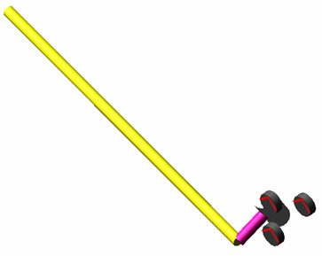
Figure 60 Relay Rod Simple Steering
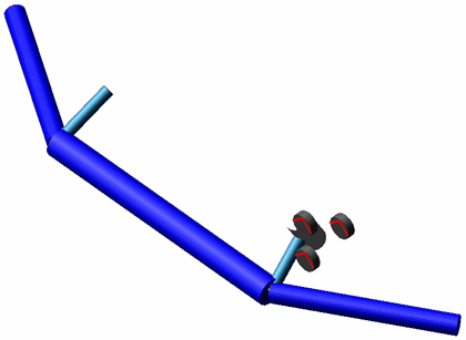
Figure 61 Pitman Arm Simple Steering
Template name
_relay_pitman_simple
Major role
Steering
Application
Suspension and full-vehicle assemblies
Description
This template is modified version of the Relay and Pitman Advanced Steering System template. In this template, steering column is simplified. There is no geometry and hardpoints to define the steering column profile. It has steering wheel, auxiliary steering column and intermediate shaft part defined at a single location.
Files referenced
Property files, hydraulic_steering_assist.ste or torsion_bar.ste and steering_compliance.ste are stored in the steer_assist.tbl of the acar_concept database. These defines the steering hydraulic assist force, torsion bar and steering compliance respectively.
Topology
The topology for relay and pitman mechanism is identical to the Relay and Pitman Advanced Steering System template.
Parameters
Communicators
Relay Pitman Tilt 3 Universal Joint Steering System
Overview
The Relay Pitman tilt 3ujoint steering template is a combination of Rack and Pinion Tilt 3 Universal Joint Steering System and Relay and Pitman Simple Steering System templates available in acar concept database.

Figure 62 Relay rod tilt 3ujoint steering
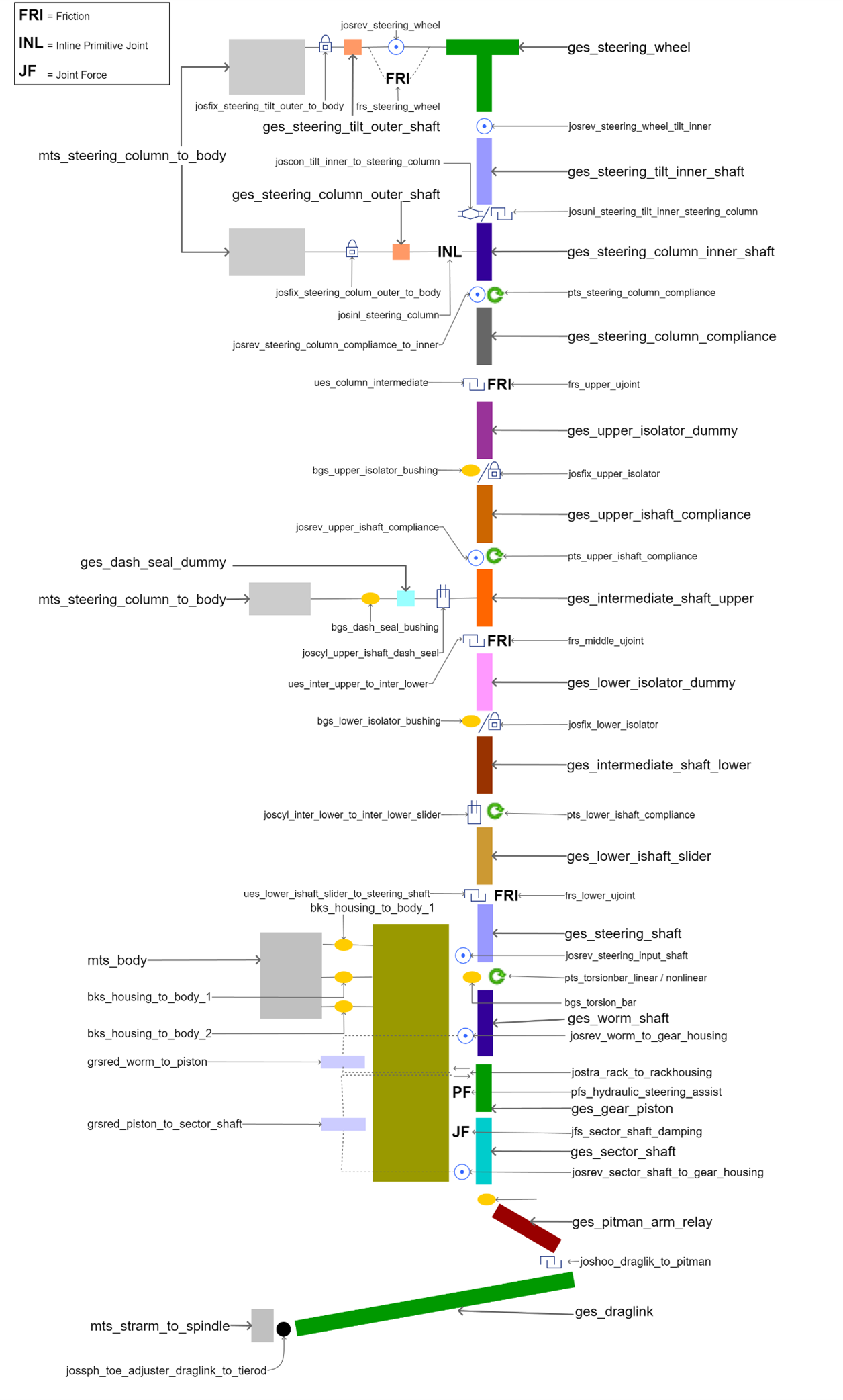
Figure 63 Relay rod tilt 3ujoint steering topology
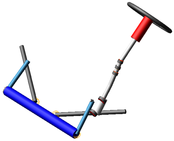
Figure 64 Pitman tilt 3ujoint steering
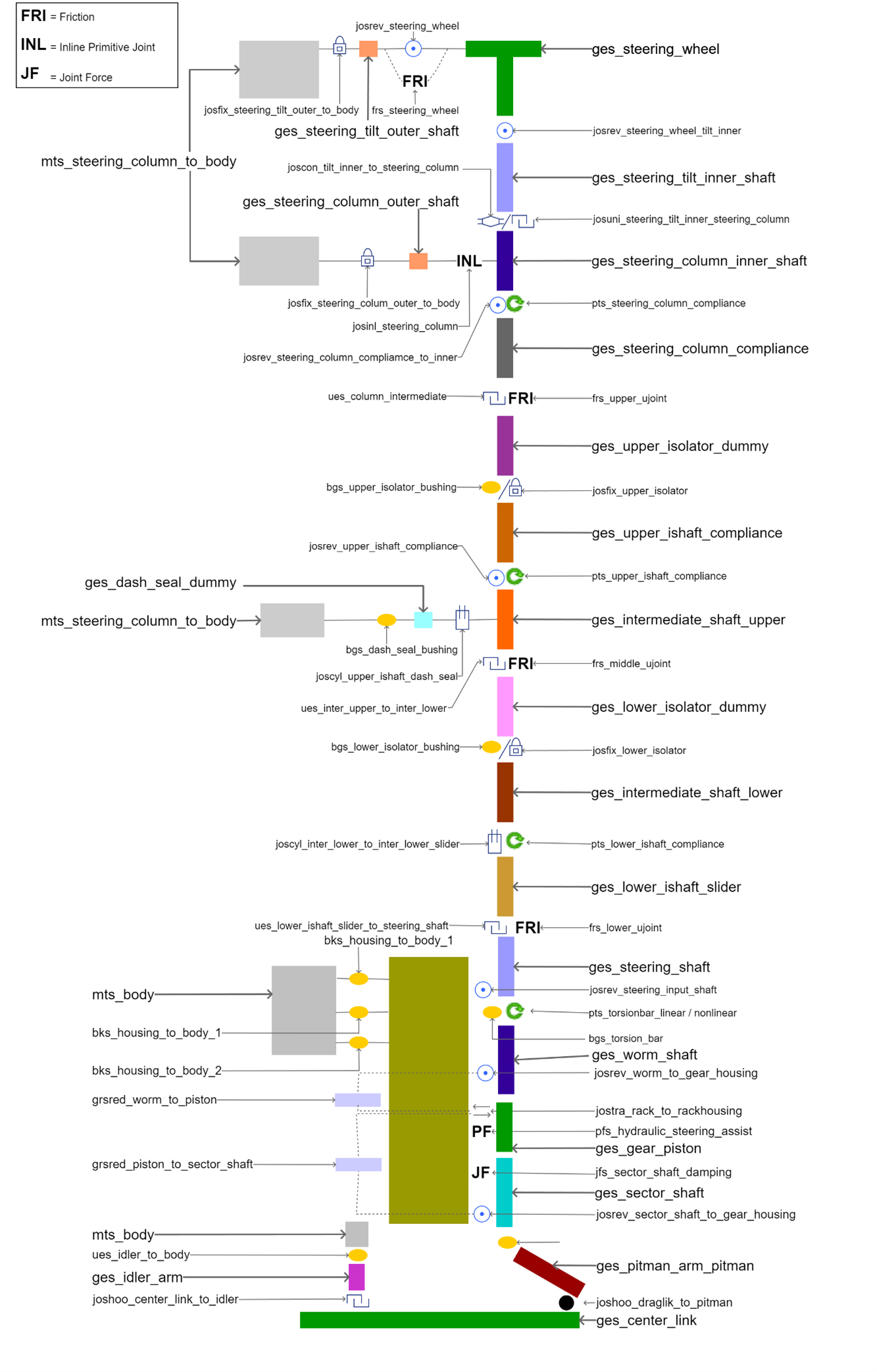
Figure 65 Pitman tilt 3ujoint steering topology
Template name
_relay_pitman_tilt_3ujoint_steering
Major role
Steering
Application
Suspension and full-vehicle assemblies
Description
This template is a combination of Rack and Pinion Tilt 3 Universal Joint Steering System and Relay and Pitman Simple Steering System templates available in acar concept database. Steering column is similar to Rack and Pinion Tilt 3 Universal Joint Steering System and steering gear is similar to that of Relay and Pitman Simple Steering System templates.
In pitman steering gear type, tierod is part of steering system.
The compliance for intermediate shaft is split into upper and lower intermediate shaft compliance. Also, upper and lower isolators are provided.
The dash seal compliance option is provided in this template. It can be attached to upper, lower or steering shaft using "dash_seal_attach" switch part.
The value of each of this design options can be set using respective parameter variables.
For more information, see Advanced Steering Design Options.
Files referenced
Property files, hydraulic_steering_assist.ste or electric_steering_assist.ste or torsion_bar.ste and steering_compliance.ste are stored in the steer_assist.tbl of the acar_concept database. These defines the steering hydraulic assist force, electric steering assist, torsion bar and steering compliance respectively.
Topology
Refer Rack and Pinion Tilt 3 Universal Joint Steering System for steering column topology
and relay and pitman advanced steering for steering gear topology.
Parameters
These integer parameter variables allow you to activate and deactivate the various Advanced Steering Design Options.
Refer Rack and Pinion Tilt 3 Universal Joint Steering System for steering column related parameter variables, Relay and Pitman Simple Steering System for steering gear related parameter variables.
Communicators
Refer Rack and Pinion Tilt 3 Universal Joint Steering System for steering column related, Relay and Pitman Simple Steering System gear related.
Rigid Chassis Body on Frame
Overview
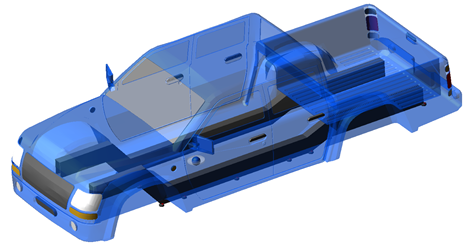
Figure 66 Rigid Chassis Body on Frame
Template name
_rigid_chassis_bof
Major role
Body
Application
Full-vehicle assemblies
Description
The vehicle body is modeled as two separate parts named as frame and body. The two parts are connected by up to nine bushings pairs.
Number of active bushings between frame and body can be set using design options Number of Body Mounts.
Files referenced
Bushings property files and graphics files in the Adams Car acar_concept database, in the shell_graphics.tbl directory.
Topology
The topology is identical to the Rigid Chassis template except body mounts options
The following table maps the topology of the template:
The joint: | Connects the part: | To the part: |
|---|---|---|
josfix_frame_to_body | ges_body | ges_frame |
Parameters
The integer parameter variable pvs_body_mounts allows you to activate and configure the body to frame mount bushings.
Additional parameters to the Rigid Chassis template are listed below:
The parameter: | Takes the value: | Its units are: | Description |
|---|---|---|---|
pvs_number_of_body_mounts | Integer | No units | 0 = None 1-9 = No of body mounts |
Communicators
Additional communicators to the Rigid Chassis template are listed below
The communicator: | Belongs to the class: | Has the role: |
|---|---|---|
co[lr]_body_mount_generic | mount | inherit |
Rigid Chassis Body and Bed on Frame
Overview
The rigid chassis body and bed on frame is a modified version of Rigid Chassis Body on Frame. In this template, the body is divided into two parts.
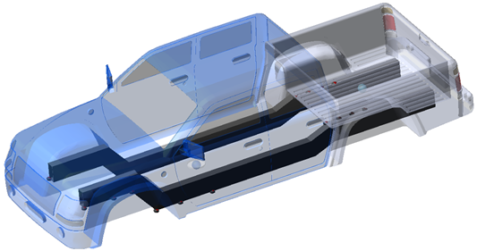
Figure 67 Rigid Chassis Body and Bed on Frame
Template name
_rigid_chassis_bed_bof
Major role
Body
Application
Full-vehicle assemblies
Description
In rigid chassis body and bed on frame template body is divided into two parts body and bed. The body and bed both are connected to frame by up to nine bushings pairs each.
Additionally, Number of active bushings between frame and body can be set using design options Number of Body Mounts. Number of active bushings between bed and frame can be set using design options Number of Bed Mounts.
Files referenced
Bushing property files and graphics files in the Adams Car acar_concept database, in the shell_graphics.tbl directory.
Topology
The topology is identical to the Rigid Chassis Body on Frame template except bed mounts options
The following table maps the topology of the template:
The joint: | Connects the part: | To the part: |
|---|---|---|
josfix_frame_to_bed | ges_bed | ges_frame |
josfix_frame_to_body | ges_body | ges_frame |
Parameters
The integer parameter variables allow you to activate and configure the body and bed to frame mount bushings.
Additional parameters to the Rigid Chassis Body on Frame template are listed below
The parameter: | Takes the value: | Its units are: | Description |
|---|---|---|---|
pvs_number_of_bed_mounts | Integer | No units | 0 = None 1-9 = No of bed mounts |
pvs_number_of_body_mounts | Integer | No units | 0 = None 1-9 = No of body mounts |
Communicators
Refer to the Rigid Chassis Body on Frame.
Rigid Chassis Convertible
Overview
The rigid chassis convertible is a modified version of the Rigid Chassis template.
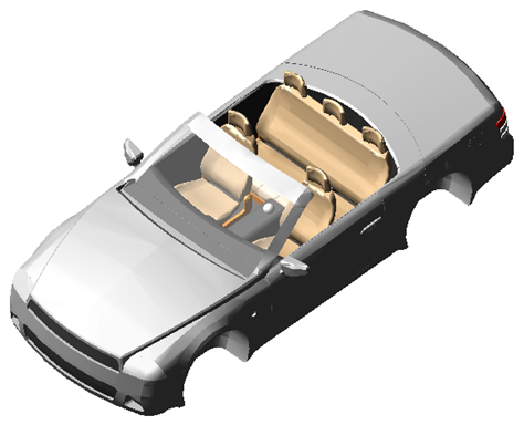
Figure 68 Rigid Chassis Convertible
Template name
_rigid_chassis_convertible
Major role
Body
Application
Full-vehicle assemblies
Description
This body system is identical to the Rigid Chassis template except for the graphics.
Files referenced
Graphics files in the Adams Car acar_concept database, in the shell_graphics.tbl directory.
Rigid Chassis Crossover
Overview
The rigid chassis crossover is a modified version of the Rigid Chassis template.
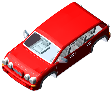
Figure 69 Rigid Chassis Crossover
Template name
_rigid_chassis_crossover
Major role
Body
Application
Full-vehicle assemblies
Description
This body system is identical to the Rigid Chassis template except for the graphics.
Files referenced
Graphics files in the Adams Car acar_concept database, in the shell_graphics.tbl directory.
Rigid Chassis Pickup
Overview

Figure 70 Rigid Chassis Pickup
Template name
_rigid_chassis_pickup
Major role
Body
Application
Full-vehicle assemblies
Description
The pickup chassis is almost identical to the Rigid Chassis, except for graphics and the addition of a payload part.
Files referenced
Graphics files in the Adams Car acar_concept database, in the shell_graphics.tbl directory.
Topology
The topology is identical to the Rigid Chassis template except for the addition of a payload part.
The following table maps the topology of the template:
The joint: | Connects the part: | To the part: |
|---|---|---|
josfix_payload_to_body | ges_payload | ges_chassis |
Parameters
Refer to the Rigid Chassis template.
Force function description
Adams Car expects air density and area parameter through property file in fixed standard units, that is, kg/m3 for air density and m2 for area.
As a result of an air stream interacting with the vehicle, forces and moments are imposed on the vehicle. All forces and moments are modeled in the template. Depending on the aerodynamic parameters supplied through property file required force and moment are calculated. In detail:


The pitching moment acts to transfer weight between the front and rear axles. It arises because the drag does not act at the ground plane. Therefore, it accounts for the elevation of the drag force. For the moment equation, a characteristic length is required to achieve dimensional consistency in the equation. So, the vehicle wheelbase is used.
Communicators
Additional communicators to the Rigid Chassis template are listed below:
The communicator: | Belongs to the class: | Has the role: |
|---|---|---|
ci[lr]_aero_force_front | location | front |
ci[lr]_aero_force_rear | location | rear |
cis_aero_pitch_angle | parameter_real | inherit |
cis_aero_pitch_angle_brake | parameter_real | inherit |
co[lr]_body_mount_generic | mount | inherit |
cos_downforce_coefficient | parameter_real | inherit |
cos_downforce_brake_coefficient | parameter_real | inherit |
cos_drag_brake_coefficient | parameter_real | inherit |
cos_front_aero_location | marker | inherit |
Rigid Chassis Two Body
Overview
The rigid chassis two body template is an extended version of the Rigid Chassis template.
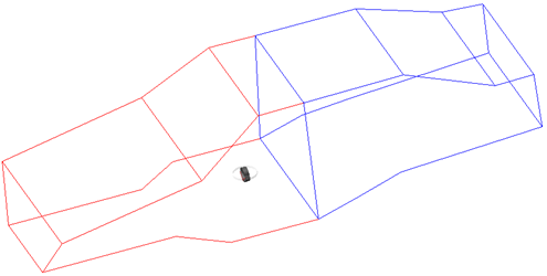
Figure 71 Rigid Chassis Two Body
Template name
_rigid_chassis_two_body
Major role
Body
Application
Full-vehicle assemblies
Description
The vehicle body is modeled as two separate rigid parts named as body front and body rear. The two parts are connected at the CG location of the body by a joint and a bushing.
The compliance between front and rear body are modelled with three configurations: "Torsion", "Torsion and Lateral Bending" and "Torsion, Vertical and Lateral Bending".
These configurations can be set by using the design options Body Compliance.
Files referenced
Bushing property files
Topology
The topology is identical to the Rigid Chassis template except front to rear body compliance options
The following table details the possible topologies for front to rear body compliance options:
The joint: | Connects the part: | To the part: |
|---|---|---|
Torsion Configuration | ||
bgs_chassis_front_to_chassis_rear_1 | ges_body_front | ges_body_rear |
josrev_chassis_front_to_chassis_rear_1 | ges_body_front | ges_body_rear |
Torsion and Lateral Bending Configuration | ||
bgs_chassis_front_to_chassis_rear_2 | ges_body_front | ges_body_rear |
joshoo_chassis_front_to_chassis_rear_2 | ges_body_front | ges_body_rear |
Torsion, Vertical and Lateral Bending Configuration | ||
bgs_chassis_front_to_chassis_rear_3 | ges_body_front | ges_body_rear |
jossph_chassis_front_to_chassis_rear_3 | ges_body_front | ges_body_rear |
Parameters
The integer parameter variable pvs_body_compliance allows you to configure the compliance between front and rear body parts.
Additional parameters to the Rigid Chassis template are listed below
The parameter: | Takes the value: | Its units are: | Description |
|---|---|---|---|
pvs_body_compliance | Integer | No units | 1 = Torsion Only, 2 = Torsion and Lateral Bending, 3 = Torsion and Vertical and Lateral Bending |
Communicators
Refer to the Rigid Chassis.
Rigid Chassis Sedan
Overview
The rigid chassis sedan is a modified version of the Rigid Chassis template.
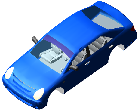
Figure 72 Rigid Chassis Sedan
Template name
_rigid_chassis_sedan
Major role
Body
Application
Full-vehicle assemblies
Description
This body system is identical to the Rigid Chassis template except for the graphics.
Files referenced
Graphics files in the Adams Car acar_concept database, in the shell_graphics.tbl directory.
Rigid Chassis Subcompact
Overview
The rigid chassis subcompact is a modified version of the Rigid Chassis template.
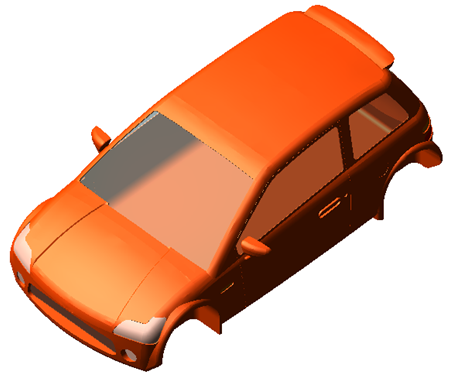
Figure 73 Rigid Chassis Subcompact
Template name
_rigid_chassis_subcompact
Major role
Body
Application
Full-vehicle assemblies
Description
This body system is identical to the Rigid Chassis template except for the graphics.
Files referenced
Graphics files in the Adams Car acar_concept database, in the shell_graphics.tbl directory.
SAE 3-Link Leaf Spring
Overview
The SAE 3-link leaf spring template consists only of the springs themselves, without any suspension members. The leaf spring design provides advantages in packaging, and it is generally used for light trucks and heavy-duty vehicles.
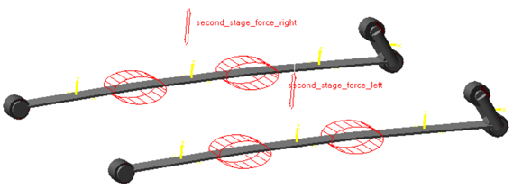
Figure 74 SAE 3-link Leaf Spring
Template name
_sae_3_link
Major role
Leaf_spring
Application
Suspension and full-vehicle assemblies
Description
The leaf spring template represents the most common spring design for solid axle suspensions. You can use the template in conjunction with a front or rear suspension.
This leaf spring is modelled using 3 rigid links connected using two torsional joint attachments. Leaf spring stiffness depends on the rotational stiffness of torsional joint attachments.
Second stage stiffness is set using the pvs_second_stage_rate and pvs_second_stage_length variables.
Files referenced
Bushing property files.
Topology
The SAE 3-link leaf springs are modelled as a series of 3 rigid bodies connected by two torsional joint attachments. Bushings connect the leaf spring and shackle to the body mount parts. The leaf spring seat is connected to the axle during assembly by an output communicator.
The following table lists the topological information of the leaf spring system.
The bushing: | Connects the part: | To the part: |
|---|---|---|
bg[lr]_leaf_at_shackle | shackle | rear_leaf |
bg[lr]_leaf_at_frame | front_leaf | mt[lr]_leaf_to_frame |
bg[lr]_shackle_at_frame | shackle | mt[lr]_shackle_to_frame |
tj[lr]_front_torsional | front_leaf | mid_leaf |
tj[lr]_rear_torsional | rear_leaf | mid_leaf |
Communicators
Mount parts provide the connectivity from the template to the body subsystem. Output communicators publish the leaf spring seat part to the appropriate suspension subsystem. The following table lists the input and output communicators in the template.
The communicator: | Belongs to the class: | Has the role: |
|---|---|---|
ci[lr]_leaf_to_frame | mount | inherit |
ci[lr]_shackle_to_frame | mount | inherit |
ci[lr]_second_stage_to_frame | mount | inherit |
co[lr]_leaf_to_axle | mount | inherit |
Semi-Trailing Arm Advanced Suspension
Overview
The semi trailing arm advanced suspension template is based on the version of Semi Trailing Arm Rear Suspension from Adams Car. The trailing arm suspension template is one of the most simple and economical designs for independent suspensions
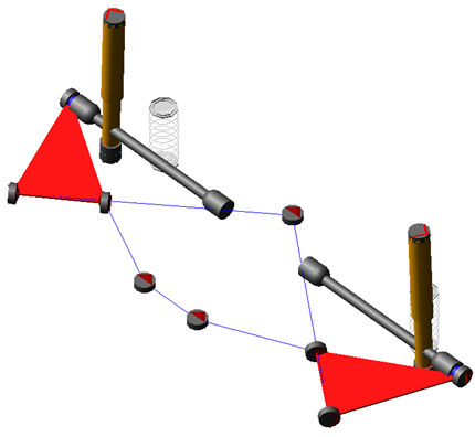
Figure 75 Semi Trailing Arm Suspension
Template name
_semi_trailing_arm_advanced
Major role
Suspension
Application
Suspension and full-vehicle assemblies
Description
This template is identical to the trailing arm suspension template available in acar shared database with the additional features of design options, toe adjuster and camber adjuster.
These design options can be useful when you want to make changes to groups of entities in the standard interface. Toe and camber adjuster lets you to adjust the toe and camber desired values at static position.
Files referenced
Bushings, springs, dampers, and bumpstop property files.
Topology
The following tables maps the topology of the trailing arm suspension.
The joint: | Connects the part: | To the part: |
|---|---|---|
jklrev_arm_inner_pivot | gel_trailing_arm | gel_camber_adjuster |
joltra_toe_split | gel_toe_adjuster | gel_camber_adjuster |
joltra_camber_split | gel_camber_adjuster | sws_subframe_attachment_options |
josfix_subframe_rigid | ges_subframe | mts_subframe_to_body |
jklhoo_top_mount_kinematic | gel_upper_strut | swl_damper_upper_attachment_options |
jolcyl_lwr_upr_strut | gel_lower_strut | gel_upper_strut |
joltra_tripot_to_differential | gel_tripot | mtl_tripot_to_differential |
jolcon_drive_sft_int_jt | gel_tripot | gel_drive_shaft |
jolcon_drive_sft_otr | gel_drive_shaft | gel_spindle |
jklhoo_lwr_strut_kinematic | gel_lower_strut | gel_trailing_arm |
Hub Compliance Active | ||
jolsph_hub_compliance | gel_spindle | gel_upright |
Hub Compliance Inactive | ||
jolrev_spindle_upright | gel_spindle | gel_upright |
Parameters
These integer parameter variables allow you to activate and deactivate the various configuration options. Only those parameters additional to the trailing arm suspension template are listed below.
The parameter: | Takes the value: | Its units are: | Description |
|---|---|---|---|
phs_subframe | Integer | No units | 0 = None, 1 = Compliant, 2 = Kinematic |
pvs_rear_subframe_mounts | Integer | No units | 1 = One, 2 = Two |
pvs_subframe_midmounts | Integer | No units | 0 = None, 1 = Front Only, 2 = Rear Only, 3 = Both |
pvs_hub_compliance | Integer | No units | 0 = Inactive, 1 = Active |
pvs_perch | Integer | No units | 0 = Inactive, 1 = Active |
pvs_number_of_bumpstops | Integer | No units | 0 = None, 1 = One, 2 = Two |
pvs_number_of_reboundstops | Integer | No units | 0 = None, 1 = One, 2 = Two |
pvs_number_of_springs | Integer | No units | 1 = One, 2 = Two |
pvs_toe_adjuster | integer | No units | 1=STA |
pvs_camber_adjuster | integer | No units | 1=STA |
Communicators
For Communicators details refer to the Trailing Arm Suspension template.
Simple Gearbox
Overview
The simple gearbox models a five-speed manual transmission with as few degrees of freedom as possible.
Template name
_simple_gearbox
Major role
Environment
Application
Full-vehicle assemblies
Description
The simple gearbox template models a five-speed manual transmission with only one degree of freedom.
Topology
The model consists of two action-only torque actuators. One applies reaction torque to the flywheel, while the other applies output torque to the transmission output shaft. The torque is based on a linear stiffness and damping multiplied by the angular difference between crankshaft and transmission output, scaled by the current gear ratio.
Parameters
The following table lists the parameters in the template.
The parameter: | Takes the value: | Its units are: |
|---|---|---|
pvs_gear_ratio_1-5 | Real | none |
pvs_max_gears | Integer | none |
pvs_transmission_efficiency | Real | none |
pvs_trans_damping | Real | torsion_damping |
pvs_trans_stiffness | Real | torsion_stiffness |
Limitations
This template is as simple as possible, so there are many limitations. Use the standard powertrain template or a Driveline gearbox template if you need more fidelity.
Communicators
The following table lists the communicators in the template.
The communicator: | Belongs to the class: | Has the role: | Matching name: |
|---|---|---|---|
cis_clutch_demand | solver_variable | inherit | clutch_demand |
cis_crankshaft_torque | solver_variable | inherit | crankshaft_torque |
cis_engine | mount | any | engine |
cis_flywheel | mount | any | flywheel, engine_out |
cis_initial_engine_rpm | parameter_real | any | initial_engine_rpm |
cis_sse_diff1 | differential_equation | any | sse_diff1 |
cis_transmission_demand | solver_variable | inherit | transmission_demand |
cis_transmission_output | mount | front | transmission_output |
cis_transmission_output_omega | solver_variable | any | transmission_output_omega |
cos_gear_ratio | parameter_variable | inherit | gear_ratio |
cos_max_gears | parameter_integer | inherit | max_gears |
cos_output_shaft_location | location | any | transmission_output_shaft_location, diff_input_location |
cos_powertrain_type | parameter_integer | any | powertrain_type, gse_powertrain_type |
cos_transmission_efficiency | parameter_real | inherit | transmission_efficiency |
cos_transmission_input_omega | solver_variable | inherit | transmission_input_omega |
cos_transmission_output_orientation | orientation | any | transmission_output_orientation |
cos_transmission_spline | spline | inherit | transmission_spline |
Solid Axle Suspension
Overview
The solid axle suspension is a dependent suspension model intended for use only as a rear suspension. It does not include springs or any locating arms. It should be assembled with another template such as the Leaf Spring system.
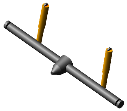
Figure 76 Solid Axle Suspension
Template name
_solid_axle
Major role
Suspension
Application
Suspension and full-vehicle assemblies
Description
The solid axle suspension template represents a common rear dependent suspension design. It does not include any locating links such as trailing arms or a panhard rod. The suspension is non-steerable and intended to be used as a rear suspension only. The model does include axle shafts that connect to the rear differential outputs.
Files referenced
Spring, damper, and bushing property files.
Topology
The axle housing attaches to leaf springs through the use of mount parts. Axle shafts attach to rear differential outputs. The axle shafts are intended to attach to the wheels.
The following table maps the topology of the solid axle suspension.
The joint: | Connects the part: | To the part: |
|---|---|---|
jk[lr]con_lower_shock | ge[lr]_lower_shock | ges_axle_housing |
jk[lr]_upper_shock | ge[lr]_upper_shock | mt[lr]_shock_to_frame |
jo[lr]cyl_shock | ge[lr]_upper_shock | ge[lr]_lower_shock |
jo[lr]fix_diff_output_to_axle | mt[lr]_diff_output | ge[lr]_axle |
jo[lr]fix_leaf_to_axle | mt[lr]_leaf_to_axle | ges_axle_housing |
Parameters
The only parameter is the kinematic flag, which controls the activity of the bushings and joints that connect the dampers to the axle and chassis.
The parameter: | Takes the value: | Its units are: |
|---|---|---|
phs_kinematic_flag | Integer | No units |
Communicators
The following table lists the Communicators in the template.
The communicator: | Belongs to the class: | Has the role: |
|---|---|---|
ci[lr]_diff_output | mount | any |
ci[lr]_diff_output_location | location | rear |
ci[lr]_leaf_to_axle | mount | inherit |
ci[lr]_shock_to_frame | mount | inherit |
ci[lr]_tire_force | force | inherit |
co[lr]_lddrv_outside_whl_mount | mount | inherit |
co[lr]_lddrv_suspension_mount | mount | inherit |
co[lr]_lddrv_upright_mount | mount | inherit |
co[lr]_ride_height_ref | marker | inherit |
co[lr]_wheel_center | location | inherit |
cos_diff_housing | mount | inherit |
cos_diff_input_location | location | inherit |
cos_suspension_parameters_ARRAY | array | inherit |
Solid Axle Trailing Arm Suspension
Overview
The Solid axle trailing arm suspension is a dependent suspension model intended for use only as a rear suspension. Trailing arm link is modelled using beam elements. It can be used with Coil or Air spring.
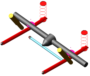
Figure 77 Solid Axle Trailing Arm Suspension
Template name
_solid_axle_trailing_arm
Major role
Suspension
Application
Suspension and full-vehicle assemblies
Description
The Solid axle trailing arm suspension is a dependent suspension model intended for use only as a rear suspension. Trailing arm link is modelled using beam elements. It can be used with Coil or Air spring.
This template has design options to set pan hard rod and hub compliance active or inactive.
This model does not include axle shafts that connect to the rear differential outputs.
Files referenced
Spring, damper, and bushing property files.
Topology
The following table maps the topology of the Solid Axle trailing arm suspension.
The joint: | Connects the part: | To the part: |
|---|---|---|
jo[lr]cyl_shock | ge[lr]_upper_shock | ge[lr]_lower_shock |
cn[lr]_lower_shock | ge[lr]_lower_shock | ges_axle |
cn[lr]_damper_upper | ge[lr]_upper_shock | mt[lr]_shock_to_frame |
jo[lr]per_damper_upper | ge[lr]_upper_shock | mt[lr]_shock_to_frame |
jo[lr]rev_hub_compliance_to_hub | ge[lr]_hub_compliance | ge[lr[_hub |
Hub Compliance off | ||
jo[lr]fix_hub_compliance | ge[lr[_hub | ges_axle |
Hub Compliance on | ||
jo[lr]sph_hub_compliance | ge[lr[_hub | ges_axle |
Parameters
The following table lists the parameters in the template. These integer parameter variables allow you to activate and deactivate the various configuration options.
The parameter: | Takes the value: | Its units are: |
|---|---|---|
phs_kinematic_flag | Integer | No units |
pvs_hub_compliance | Integer | No units |
pvs_panhard_rod | Integer | No units |
pvs_number_of_bumpstops | Integer | No units |
pvs_number_of_reboundstops | Integer | No units |
pv[lr]_toe_angle | Real | No units |
pv[lr]_camber_angle | Real | No units |
pvs_hub_compliance_offset | Real | No units |
Communicators
The following table lists the Communicators in the template.
The communicator: | Belongs to the class: | Has the role: |
|---|---|---|
ci[lr]_shock_to_frame | mount | inherit |
ci[lr]_spring_to_body | mount | inherit |
ci[lr]_trailing_arm_to_body | mount | inherit |
cis_body | mount | inherit |
ci[lr]_ARB_pickup | location | inherit |
co[lr]_arb_bushing_mount | force | inherit |
co[lr]_droplink_to_suspension | mount | inherit |
co[lr]_suspension_mount | mount | inherit |
co[lr]_suspension_upright | mount | inherit |
cos_axle | marker | inherit |
cos_suspension_parameters_ARRAY | array | inherit |
co[lr]_wheel_center | location | inherit |
Stabilizer Bar system
The stabilizer bar system is the advanced version of Anti-roll bar system (discrete flexible links). Additional design option is added to switch droplink bar with spring damper.
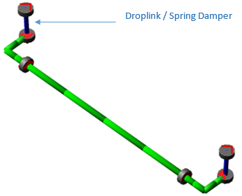
Figure 78 Stabilizer bar system
Template name
_stabilizer_bar
Major role
antirollbar
Application
Suspension and full-vehicle analyses
Description
This stabilizer bar template provides a beam element model of stabilizer bar (also known as anti-roll bar). It consists of several rigid body parts connected by beam forces. The outer radius and inner radius are parameterized, allowing you to model a solid or hollow cross-section.
Additionally, user can switch the droplink to spring damper configuration by setting parameter variable pvs_droplink_active to 0.
Files referenced
Bushing property files
Topology
Left and right bushings attach the bar to the body or to the suspension subframe. Drop links transmit the suspension motion to the bar ends. The drop links attach to the suspension with spherical joints connector and to the bar ends with convel joints connector.
The following table maps the topology of the stabilizer bar system template.
The joint: | Connects the part: | To part |
|---|---|---|
cn[lr]_droplink_external | ge[lr]_droplink | mt[lr]_droplink_to_suspension |
cns_droplink_to_single_bar_[left/right] | ge[lr]_droplink | ars_[1/7]_stabilizer bar |
Limitations
The anti-roll bar system template represents an approximation of a stabilizer bar. For more complex solutions (for example, complex ARB geometry or large deflections), you would need to create a more accurate representation of the bar using flexible bodies or FE parts.
Parameters
When you turn on the spring damper configuration you can specify the stiffness and damping using parameter variables.
The parameter: | Takes the value: | Its units are: | Description |
|---|---|---|---|
phs_droplink_active | Integer | No units | 0 = Link in form of Spring damper 1 = Rigid link |
pvl_link_spring_rate | Real | Stiffness | |
pvl_link_damping_rate | Real | Damping |
Communicators
Additional output communicators are listed below:
The communicator: | Belongs to the class: | Has the role: |
|---|---|---|
co[lr]_arb_droplink_joint | joint | inherit |
co[lr]_arb_droplink_joint | bushing | inherit |
Trailer
Overview
This template represents a solid axle suspension typically used on trailers along with design options to configure it with different trailer body, hitch configurations, number of trailer cargo parts, load equalizer, number of trailer axles and hub compliance.
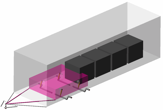
Template name
_trailer
Major role
Suspension
Application
Suspension and Full-vehicle analysis
Description
This template represents few of the below trailer suspension configurations…
a. simple rigid axle suspension with springs.
b. simple independent trailing arm suspension with torsional springs
c. simple independent trailing arm suspension with spherical joint and bushing
Additionally, below design options are available to configure this trailer suspension.
The trailer body is modeled with two configuration options: Simple and Advanced. These configurations can be changed using the design options Trailer Body Configuration.
The number of trailer axles can be set using design option "Number of Trailer Axles".
The axle is modeled with three options: Solid Axle, Trailing Arm with Torsion Spring and Trailing Arm with Bushing. These configurations can be changed using the design options Trailer Axle Configuration. This defines trailing arm attachment with the trailer body.
The Hitch Joint Method options will determine whether hitch configurations modelling is Kinematic or Compliant or Lock (fix Joint).
The hitch is modeled with three options: Standard, Goose Neck and Fifth Wheel. These configurations can be changed using the design options Hitch Configuration. This defines trailer body attachment with the truck or body.
In Fifth Wheel Hitch Configuration, joint between fifth wheel head support and vehicle body is modeled as either a revolute/bushing (x axis motion) or a fixed joint (no x axis motion) this can be changed using design option Fifth Wheel Motion.
Load Equalizer design option used to activate or deactivate spring bar and associated forces and constraints which are used for load levelling or weight distribution
The number of trailer cargo parts can be set using design option "Number of Trailer Cargo Parts". You can add four trailer cargo parts.
You can activate or deactivate the effect of Hub Compliance using the pvs_hub_compliance parameter variable or using design option Hub Compliance.
Files referenced
Bushings, springs, damper files
Topology
Hub parts are connected to the solid axle via rotational joints. The trailer wheel template (trailer_wheels_dual.tpl) mounts to the hubs. The suspension is connected to the truck (body) subsystem via mount parts at the hitch joint.
The following table details the topologies for different configuration options.
Design Option | The joint: | Connects the part: | To the part: |
|---|---|---|---|
Trailer Axle Configuration: Solid Axle | josfix_axle_simple | gel_axle1 | ger_axle1 |
jostra_trailer_body_simple_to_axle | ges_trailer_body | gel_axle1 | |
josfix_axle2_simple | gel_axle2 | ger_axle2 | |
jostra_trailer_body_simple_to_axle2 | ges_trailer_body | gel_axle2 | |
Trailer Axle Configuration: Trailing Arm with Torsion Spring | ue[lr]_axle1_to_trailer_body_adv | ge[lr]_axle1 | ges_trailer_body |
ue[lr]_axle2_to_trailer_body_adv | ge[lr]_axle2 | ges_trailer_body | |
Trailer Axle Configuration: Trailing Arm with Bushing | jo[lr]sph_axle1_to_trailer_body_adv | gel_axle1 | ges_trailer_body |
jo[lr]sph_axle2_to_trailer_body_adv | gel_axle2 | ges_trailer_body | |
bg[lr]_axle1_trailer_body_adv | gel_axle1 | ges_trailer_body | |
bg[lr]_axle2_trailer_body_adv | gel_axle2 | ges_trailer_body | |
Hitch Configuration: Standard, Goose Neck & Fifth Wheel Hitch Joint Method: Lock | josfix_trailer_body_to_chassis_lock | ges_trailer_body | mts_body |
Hitch Configuration: Standard & Goose Neck Hitch Joint Method: Kinematic | jossph_trailer_body_to_chassis | ges_trailer_body | mts_body |
Hitch Configuration: Standard & Goose Neck Hitch Joint Method: Compliance | bgs_trailer_body_chassis | ges_trailer_body | mts_body |
Hitch Configuration: Fifth Wheel Hitch Joint Method: Kinematic | josrev_trailer_body_to_fifth_wheel_head | ges_trailer_body | ges_fifth_wheel_head |
josrev_fifth_wheel_head_to_head_support | ges_fifth_wheel_head | ges_fifth_wheel_head_support | |
josrev_fifth_wheel_head_support_to_chassis | ges_fifth_wheel_head_support | mts_body | |
josfix_fifth_wheel_head_support_to_chassis_no_x_rot | ges_fifth_wheel_head_support | mts_body | |
Hitch Configuration: Fifth Wheel Hitch Joint Method: Compliant | bgs_trailer_body_to_fifth_wheel_head | ges_trailer_body | ges_fifth_wheel_head |
bgs_fifth_wheel_head_to_head_support | ges_fifth_wheel_head | ges_fifth_wheel_head_support | |
bgs_fifth_wheel_head_support_to_chassis | ges_fifth_wheel_head_support | mts_body | |
Load Equalizer | jo[lr]rev_trailer_spring_bar_to_chassis | nr[lr]_1_trailer_spring_bar | mts_body |
pf[lr]_spring_bar_force | nr[lr]_2_trailer_spring_bar | ges_trailer_body | |
ns[lr]_spring_bar_to_trailer_body | nr[lr]_2_trailer_spring_bar | ges_trailer_body | |
Number of Trailer Cargo Parts | josfix_trailer_body_to_cargo_1 | ges_trailer_body | ges_cargo_1 |
josfix_trailer_body_to_cargo_2 | ges_trailer_body | ges_cargo_2 | |
josfix_trailer_body_to_cargo_3 | ges_trailer_body | ges_cargo_3 | |
josfix_trailer_body_to_cargo_4 | ges_trailer_body | ges_cargo_4 | |
Hub Compliance | jolsph_hub_compliance | gel_spindle | gel_axle1 |
bgl_hub_compliance | gel_spindle | gel_axle1 | |
jolsph_hub_compliance_axle2 | gel_spindle_axle2 | gel_axle2 | |
bgl_hub_compliance_axle2 | gel_spindle_axle2 | gel_axle2 | |
Damper | jolcyl_shock | gel_upper_shock | gel_lower_shock |
bgl_lower_shock_to_axle | gel_lower_shock | gel_axle1 | |
bgl_upper_shock_to_body | gel_upper_shock | ges_trailer_body | |
jolcyl_shock_axle2 | gel_upper_shock_axle2 | gel_lower_shock_axle2 | |
bgl_lower_shock_to_axle_axle2 | gel_lower_shock_axle2 | gel_axle2 | |
bgl_upper_shock_to_body_axle2 | gel_upper_shock_axle2 | ges_trailer_body |
Parameters
These integer parameter variables allow you to activate and deactivate the various configuration options.
The parameter: | Takes the value: | Its units are: | Description |
|---|---|---|---|
pvs_number_of_trailer_axles | Integer | No units | 1 = One 2 = Two |
pvs_trailer_body_configuration | Integer | No units | 1 = Simple 2 = Advanced |
pvs_trailer_axle_configurations | Integer | No units | 0 = Solid Axle 1 = Trailing Arm with Torsion Spring 2 = Trailing Arm with Bushing |
pvs_hitch_joint_method | Integer | No units | 0 = Lock 1 = Kinematic 2 = Compliance |
pvs_hitch_configuration | Integer | No units | 1 = Standard 2 = Goose Neck 3 = Fifth Wheel |
pvs_fifth_wheel_motion | Integer | No units | 1 = No X Rotation 2= Allow X Rotation |
pvs_load_equalizer | Integer | No units | 0 = Inactive, 1 = Active |
pvs_number_of_trailer_cargo_parts | Integer | No units | 0 = None 1 = One 2 = Two 3 = Three 4 = Four |
pvs_hub_compliance | Integer | No units | 0 = Inactive, 1 = Active |
pvs_damper | Integer | No units | 0 = Inactive, 1 = Active |
Communicators
Mount parts provide the connectivity to the trailer and wheel subsystems. Input communicators receive information about the toe and camber suspension orientation and the wheel-center location.
The following table lists the communicators in the template:
The communicator: | Belongs to the class: | Has the role: |
|---|---|---|
cis_body | mount | inherit |
cos_number_of_trailer_axles | parameter_integer | inherit |
co[lr]_toe_angle | parameter_real | inherit |
co[lr]_camber_angle | parameter_real | inherit |
co[lr]_ride_height_ref | marker | inherit |
co[lr]_wheel_center | location | inherit |
co[lr]_outside_wheel_center | location | inherit |
co[lr]_suspension_upright | mount | inherit |
co[lr]_suspension_mount | mount | inherit |
co[lr]_toe_angle_axle2 | parameter_real | inherit |
co[lr]_camber_angle axle2 | parameter_real | inherit |
co[lr]_wheel_center axle2 | location | inherit |
co[lr]_outside_wheel_center axle2 | location | inherit |
co[lr]_suspension_upright axle2 | mount | inherit |
co[lr]_suspension_mount axle2 | mount | inherit |
cos_suspension_parameters_ARRAY | array | inherit |
cos_suspension_parameters_ARRAY_axle2 | array | inherit |
Trailer Wheels Dual
Overview
This template represents two axles with dual wheel arrangement and is compatible with trailer template. It uses the tire property file and supports three basic functions:
■Supports vertical load
■Develops longitudinal forces for acceleration and braking
■Develops lateral forces for cornering
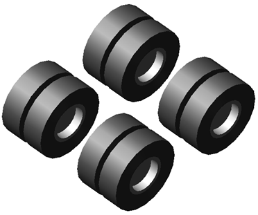
Template name
_trailer_wheels_dual
Major role
Wheel
Application
Full-vehicle analyses
Description
The dual wheel system template consists of wheel parts rigidly connected to mount parts. The tire contact patch forces are transformed in forces and torques applied at the hub. A series of user-written subroutines perform the force calculation depending on the tire property file that you selected. The road property file determines the road contact model. For additional information about using tire and road models, see the Adams Tire online help.
Dual Wheel Axle1 and Dual Wheel Axle2 design options will help to activate and deactivate dual wheels on axle1 and axle2 respectively.
The number_of_trailer_axles input communicator used to activate and deactivate rear axle wheels which gets parameter integer value from number_of_trailer_axles output communicator from trailer template.
Files referenced
The wheel system template references a tire property file for each wheel part. The default tire property file is pac2002_315_80R22_5.tir, stored in the tires.tbl directory of the Adams Car shared database.
Topology
The outside and inside wheel are rigidly connected by fixed joint, and the inside wheel in turn is connected to spindle.
Communicators
Mount parts provide connectivity to the suspension subsystems, and output communicators publish information about tire forces and wheel orientation. Tire force output communicator is used by the drive axle template in order to evaluate the halfshaft angular velocity during a quasi-static analysis. The halfshaft velocity contributes to the calculation of the engine speed during quasi-static analysis.
The following table lists the communicators in the wheel system template.
The communicator: | Belongs to the class: | Has the role: |
|---|---|---|
cis_number_of_trailer_axles | parameter_integer | inherit |
ci[lr]_camber_angle | parameter_real | inherit |
ci[lr]_outside_wheel_center | location | inherit |
ci[lr]_suspension_upright | mount | inherit |
ci[lr]_suspension_mount | mount | inherit |
ci[lr]_toe_angle | parameter_real | inherit |
ci[lr]_wheel_center | location | inherit |
ci[lr]_camber_angle_axle2 | parameter_real | inherit |
ci[lr]_outside_wheel_center_axle2 | location | inherit |
ci[lr]_suspension_upright_axle2 | mount | inherit |
ci[lr]_suspension_mount_axle2 | mount | inherit |
ci[lr]_toe_angle_axle2 | parameter_real | inherit |
ci[lr]_wheel_center_axle2 | location | inherit |
co[lr]_outside_tire_force | force | inherit |
co[lr]_tire_force | force | inherit |
co[lr]_outside_tire_force_axle2 | force | inherit |
co[lr]_tire_force_axle2 | force | inherit |
Trailing Arm Advanced Suspension
Overview
The trailing arm advanced suspension template is a converted version of SLA Trailing Arm Rear Suspension from Adams Car. It's a combination of Double Wishbone Advanced Suspension and Trailing Arm Suspension.
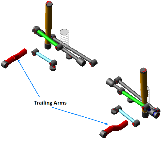
Figure 79 Trailing Arm Suspension
Template name
_trailing_arm_advanced
Major role
Suspension
Application
Suspension and full-vehicle assemblies
Description
This template is identical to the double wishbone advanced template for configuration like double ball joint lower control arm option and single link upper control arm. The tierod is not included, as it is used for rear suspension.
There are four trailing arm configuration options: 3 beam, torsional spring, upper-lower spindle, upper-lower control arms. These configurations can be changed using the design option Trailing Arm Suspension.
Files referenced
Bushings, springs, dampers, and bumpstop property files.
Topology
The following tables maps the topology of the trailing arm suspension.
The joint: | Connects the part: | To the part: |
|---|---|---|
jklsph_lca_front_balljoint | gel_lca_front_toe_adjuster | gel_upright |
jklsph_lca_rear_balljoint | gel_upright | gel_lower_control_arm2 |
joltra_lca_split | gel_lca_rear | gel_lower_control_arm2 |
jklsph_uca_outer | gel_caster_adjuster_ubj | gel_upright |
joltra_lca_toe_split | gel_lca_front_toe_adjuster | gel_lca_front |
josfix_subframe_rigid | ges_subframe | mts_subframe_to_body |
jklhoo_top_mount_kinematic | gel_upper_strut | mtl_strut_to_body |
jolcyl_lwr_upr_strut | gel_lower_strut | gel_upper_strut |
joltra_tripot_to_differential | gel_tripot | mtl_tripot_to_differential |
jolcon_drive_sft_int_jt | gel_tripot | gel_drive_shaft |
jolcon_drive_sft_otr | gel_drive_shaft | gel_spindle |
jklhoo_lwr_strut_kinematic | gel_lower_strut | gel_upright |
jklhoo_lca_front_inner | gel_lca_front | sws_subframe_attachment_options |
jklhoo_lca_rear_inner | gel_lca_rear | sws_subframe_attachment_options |
jklhoo_uca | gel_upper_control_arm | swl_uca_attachment_options |
joltra_uca_caster_split | gel_camber_adjuster_ubj | gel_caster_adjuster_ubj |
joltra_ubj_camber_split | gel_upper_control_arm | gel_camber_adjuster_ubj |
The following table maps the trailing arm configuration.
Design Option | The joint: | Connects the part: | To the part: |
|---|---|---|---|
3 Beam 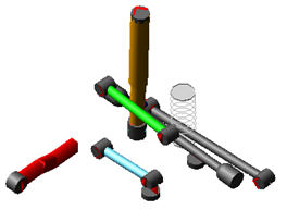 | jolsph_trailing_arm_beam_body | nrl_1_trailing_arm | mtl_trailing_arm_to_body |
jolfix_trailing_arm_beam_upright | nrl_4_trailing_arm | gel_upright | |
Torsion spring 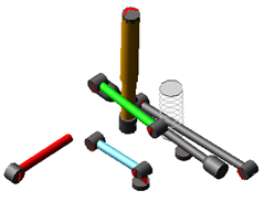 | jolsph_trailing_arm_body | gel_trailing_arm | mtl_trailing_arm_to_body |
uel_trailing_arm (revolute joint in the torsional spring ude) | gel_trailing_arm | gel_upright | |
Upper-Lower Upright 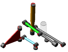 | jolsph_trailing_arm_body | gel_trailing_arm | mtl_trailing_arm_to_body |
jolsph_trailing_arm_upright_lower | gel_trailing_arm | gel_upright | |
jolsph_trailing_arm_upright_upper | gel_trailing_arm | gel_upright | |
Upper-Lower Control Arms 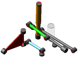 | jolsph_trailing_arm_body | gel_trailing_arm | mtl_trailing_arm_to_body |
jolsph_trailing_arm_lca_front | gel_trailing_arm | gel_lca_front | |
jolsph_trailing_arm_uca | gel_trailing_arm | gel_upper_control_arm | |
Hub Compliance Active | jolsph_hub_compliance | gel_spindle | gel_upright |
Hub Compliance Inactive | jolrev_spindle_upright | gel_spindle | gel_upright |
Parameters
These integer parameter variables allow you to activate and deactivate the various configuration options. Only those parameters additional to the Double Wishbone Advanced Suspension template are listed below.
The parameter: | Takes the value: | Its units are: | Description |
|---|---|---|---|
pvs_trailing_arm_configuration | Integer | No units | 1 = 3 Beam, 2 = Torsion Spring, 3 = Upper-Lower Upright, 4 = Upper-Lower Control Arms |
Communicators
Communicators additional to the Double-Wishbone Suspension template are listed below
The communicator: | Belongs to the class: | Has the role: |
|---|---|---|
ci[lr]_trailing_arm_to_body | mount | inherit |
Twist Beam Suspension
Overview
The twist beam suspension is a dependent suspension model intended for use only as a rear suspension. It does not include a panhard rod or drive shafts. It is a parametric model, unlike the standard Twist Beam Suspension which relies on a Modal Neutral File.
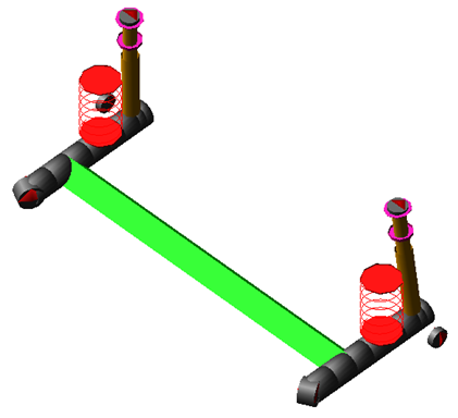
Figure 80 Twist Beam Suspension
Template name
_twist_beam
Major role
Suspension
Application
Suspension and full-vehicle assemblies
Description
This twist beam suspension template is an enhancement of the standard Twist Beam Suspension. It does not include a subframe. The suspension is non-steerable and intended to be used as a rear suspension only.
The center section of the twist beam is a flexible body generated using ViewFlex. The flexible body is attached to the trailing arms, which are modeled using non-linear beams (discrete flexible links).
Files referenced
Spring, damper, and bushing property files. The flexible body references the file <acar_concept>/flex_bodys.tbl/fbs_main_beam.mnf. If you wish to change the flex body geometry, use ViewFlex and load the file <acar_concept>/flex_bodys.tbl/fbs_main_beam.afi.
Topology
The following table maps the topology of the twist beam suspension.
The joint: | Connects the part: | To the part: |
|---|---|---|
jk[lr]hoo_upr_strut_to_body | mt[lr]_strut_to_body | ge[lr]_upper_strut |
jo[lr]con_lower_strut_to_trailing_arm | ge[lr]_lower_strut | nr[lr]_4_trailing_arm |
jo[lr]cyl_lwr_upr_strut | ge[lr]_upper_strut | ge[lr]_lower_strut |
Hub Compliance on: | ||
jo[lr]sph_hub_compliance | ge[lr]_spindle | nr[lr]_4_trailing_arm |
Hub Compliance off: | ||
jo[lr]rev_spindle | ge[lr]_spindle | nr[lr]_4_trailing_arm |
Parameters
In the twist beam suspension, toe and camber variables parameterize wheel spin axis, spindle part, and spindle geometry. The following table lists the parameters in the template.
The parameter: | Takes the value: | Its units are: |
|---|---|---|
phs_kinematic_flag | Integer | No units |
pv[lr]_toe_angle | Real | Angle |
pv[lr]_camber_angle | Real | Angle |
pvs_hub_compliance_active | Integer | No units |
pvs_hub_compliance_offset | Real | Length |
Communicators
The following table lists the communicators in the template.
The communicator: | Belongs to the class: | Has the role: |
|---|---|---|
ci[lr]_spring_to_body | mount | inherit |
ci[lr]_strut_to_body | mount | inherit |
cis_body | mount | inherit |
co[lr]_camber_angle | parameter_real | inherit |
co[lr]_ride_height_ref | marker | inherit |
co[lr]_suspension_mount | mount | inherit |
co[lr]_suspension_upright | mount | inherit |
co[lr]_toe_angle | parameter_real | inherit |
co[lr]_wheel_center | location | inherit |
cos_suspension_parameters_ARRAY | array | inherit |
Twist Beam Advanced Suspension
Overview
The trailing arm advanced suspension template is an enhanced version of the standard Twist Beam Suspension.
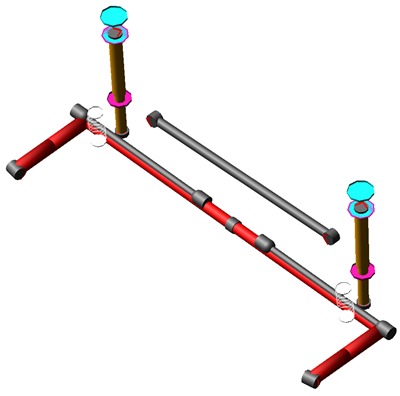
Figure 81 Twist Beam Advanced Suspension
Template name
_twist_beam_advanced
Major role
Suspension
Application
Suspension and full-vehicle assemblies
Description
This twist beam suspension template is an enhanced version of the standard Twist Beam Suspension. It does not include a subframe. The suspension is non-steerable and intended to be used as a rear suspension only.
Apart from standard Flexible body using modal neutral file, there are other nine configuration modelled into this template.
This template has options to model different twist beam configuration such as "2-piece twist with 1 beam trailing arm", "3-piece twist with 1 beam trailing arm", "Beam twist with 1 beam trailing arm", "Arm and half axle", "Curved beam twist with 1 beam trailing arm", "2-piece twist with 2 beam trailing arm", "3-piece twist with 2 beam trailing arm", "Beam twist with 2 beam trailing arm", "Curved beam twist with 2 beam trailing arm" and "Flexible body".
These configurations can be changed using the design options Twist Beam Configuration.
Files referenced
Bushings, springs, dampers, and bumpstop property files. The flexible body references the file < acar_shared >/flex_bodys.tbl/ PonteV.mnf.
Topology
The following tables maps the topology of the twist beam advanced suspension.
The joint: | Connects the part: | To the part: |
|---|---|---|
jolrev_spindle | gel_spindle | gel_pod |
jossph_panhard_body | ges_panhard_rod | mts_body |
joshoo_panhard_axle | ges_panhard_rod | sws_panhard_rod_attachment |
jklhoo_top_mount_kinematic | gel_upper_strut | swl_damper_upper_attachment_options |
jolcyl_lwr_upr_strut | gel_lower_strut | gel_upper_strut |
joltra_tripot_to_differential | gel_tripot | mtl_tripot_to_differential |
jolcon_drive_sft_int_jt | gel_tripot | gel_drive_shaft |
jolcon_drive_sft_otr | gel_drive_shaft | gel_spindle |
jklhoo_lwr_strut_kinematic | gel_lower_strut | swl_damper_lower_attachment_options |
joshoo_panhard_axle | ges_panhard_rod | sws_panhard_rod_attachment |
jossph_panhard_body | ges_panhard_rod | mts_body |
The following table maps the twist beam configurations.
Design Option | The joint: | Connects the part: | Connects the part: To the part: |
|---|---|---|---|
2-piece twist with 1 beam trailing arm  | jolsph_twist_arm_3piece_kinematic | nrl_1_twist_arm | mts_body |
jolfix_axle_to_pod | gel_axle | gel_pod | |
jolfix_twist_arm_to_trail | nrl_2_twist_arm | gel_trailing_arm | |
3-piece twist with 1 beam trailing arm  | jolsph_twist_arm_3piece_kinematic | nrl_1_twist_arm | mts_body |
jolsph_axle_middle_to_axle | ges_axle_middle | gel_axle | |
jolfix_axle_to_pod | gel_axle | gel_pod | |
jolfix_twist_arm_to_trail | nrl_2_twist_arm | gel_trailing_arm | |
Beam twist with 1 beam trailing arm 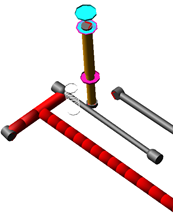 | jolsph_twist_curved_arm_kinematic | nrl_1_trailing_arm_front | mts_body |
jolfix_twist_beam_to_trailing | swl_axle_attachment_options | nrl_1_twist_beam | |
jolfix_trailing_arm_front | gel_trailing_arm | nrl_2_trailing_arm_front | |
Arm and half axle 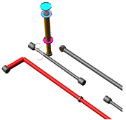 | jolsph_twist_arm_body_kinematic | gel_trailing_arm | mts_body |
jossph_trailing_arm_center | gel_trailing_arm | ger_trailing_arm | |
jolfix_trailing_arm_to_pod | gel_trailing_arm | gel_pod | |
Curved beam twist with 1 beam trailing arm 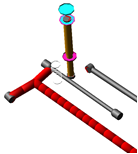 | jolsph_twist_curved_arm_kinematic | nrl_1_trailing_arm_front | mts_body |
jolfix_twist_beam_to_trailing | swl_axle_attachment_options | nrl_1_twist_beam | |
jolfix_trailing_arm_front | gel_trailing_arm | nrl_2_trailing_arm_front | |
2-piece twist with 2 beam trailing arm 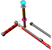 | jolsph_twist_curved_arm_kinematic | nrl_1_trailing_arm_front | mts_body |
jolfix_axle_to_pod | gel_axle | gel_pod | |
jolfix_trailing_arm_front | gel_trailing_arm | nrl_2_trailing_arm_front | |
jolfix_trailing_arm_rear | gel_trailing_arm | nrl_1_trailing_arm_rear | |
3-piece twist with 2 beam trailing arm 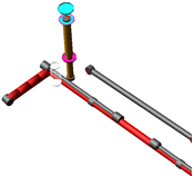 | jolsph_twist_curved_arm_kinematic | nrl_1_trailing_arm_front | mts_body |
jolsph_axle_middle_to_axle | ges_axle_middle | gel_axle | |
jolfix_axle_to_pod | gel_axle | gel_pod | |
jolfix_trailing_arm_front | gel_trailing_arm | nrl_2_trailing_arm_front | |
jolfix_trailing_arm_rear | gel_trailing_arm | nrl_1_trailing_arm_rear | |
Beam twist with 2 beam trailing arm 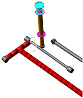 | jolsph_twist_curved_arm_kinematic | nrl_1_trailing_arm_front | mts_body |
jolfix_twist_beam_to_trailing | swl_axle_attachment_options | nrl_1_twist_beam | |
jolfix_trailing_arm_front | gel_trailing_arm | nrl_2_trailing_arm_front | |
jolfix_trailing_arm_rear | gel_trailing_arm | nrl_1_trailing_arm_rear | |
Curved beam twist with 2 beam trailing arm 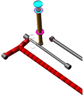 | jolsph_twist_curved_arm_kinematic | nrl_1_trailing_arm_front | mts_body |
jolfix_twist_beam_to_trailing | swl_axle_attachment_options | nrl_1_twist_beam | |
jolfix_trailing_arm_front | gel_trailing_arm | nrl_2_trailing_arm_front | |
jolfix_trailing_arm_rear | gel_trailing_arm | nrl_1_trailing_arm_rear | |
Flexible body 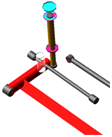 | jolrev_twist_beam_to_body | fbs_twist_beam | mts_body |
jolfix_twist_beam_to_pod | fbs_twist_beam | gel_pod | |
Spindle Compliance Active (for design Option 1,2,3,5) | jolsph_spindle_compliance | gel_trailing_arm | gel_pod |
Spindle Compliance Active (for design Option 6,7,8,9) | jolsph_spindle_compliance_2piece | nrl_2_trailing_arm_rear | gel_pod |
Spindle Compliance Inactive (for design Option 1,2,3,5) | jolfix_trailing_arm_to_pod | gel_trailing_arm | gel_pod |
Spindle Compliance Inactive (for design Option 6,7,8,9) | jolfix_trailing_arm_rear_to_pod | nrl_2_trailing_arm_rear | gel_pod |
Hub Compliance Active | jolsph_hub_compliance | gel_spindle | gel_pod |
Hub Compliance Inactive | jolrev_spindle_upright | gel_spindle | gel_pod |
Parameters
These integer parameter variables allow you to activate and deactivate the various configuration options. Only those parameters additional to the Twist Beam Suspension template are listed below.
The parameter: | Takes the value: | Its units are: | Description |
|---|---|---|---|
pvs_twist_beam_configuration | Integer | No units | 1 = 2 piece twist with 1 beam trailing arm 2 = 3 piece twist with 1 beam trailing arm 3 = Beam twist with 1 beam trailing arm 4 = Arm and half axle 5 = Curved beam twist with 1 beam trailing arm 6 = 2 piece twist with 2 beam trailing arm 7 = 3 piece twist with 2 beam trailing arm 8 = Beam twist with 2 beam trailing arm 9 = Curved beam twist with 2 beam trailing arm 10 = Flexible body |
pvs_spindle_compliance | Integer | No units | 0 = Inactive 1 = Active |
pvs_panhard_rod_active | Integer | No units | 0 = Inactive 1 = Active |
pvs_bush_angle | Real | Angle | Bush angle for trailing arm to body bush |
Communicators
Refer to standard Twist Beam Suspension.
Twin I-Beam Suspension System
Overview
The twin I-beam suspension template is a variation of the swing axle concept, where the left and right axle pivots are on opposite sides of the centerline.
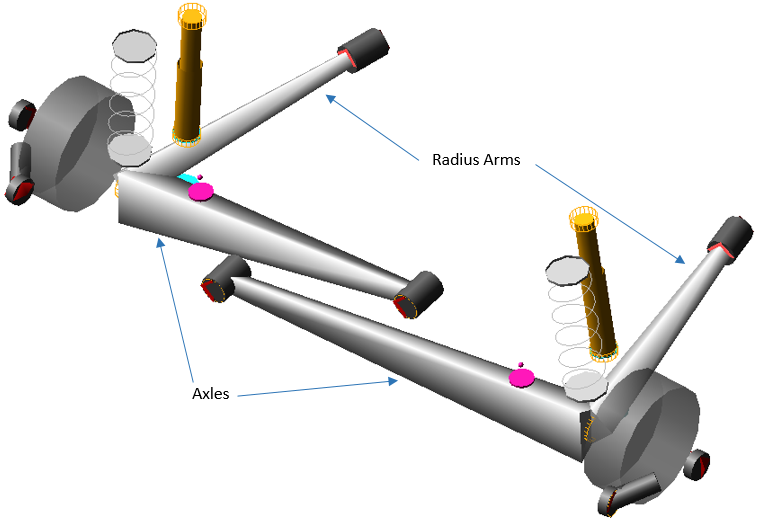
Figure 82 Twin I-Beam Suspension System
Template name
_twin_I_beam
Major role
Suspension
Application
Suspension and full-vehicle assemblies
Description
This template models a simple and robust swing axle design that has been used on millions of pickup trucks since the 1960s. It is meant to be used as a front suspension, paired with a steering template such as the Draglink Steering System.
Files referenced
Bushing, spring, damper, bumpstop and reboundstop property files.
Topology
Bushings attach the radius arms and axles to the chassis. Springs, dampers, bumpstops and reboundstops act on either the radius arms or axles. The following table maps the topology of the template.
The joint: | Connects the part: | To the part: |
|---|---|---|
jo[lr]rev_camber_adjustment | ge[lr]_camber_adjuster | ge[lr]_caster_adjuster |
jo[lr]rev_caster_adjustment | ge[lr]_caster_adjuster | ge[lr]_I_beam_axle |
jo[lr]rev_hub_spindle | ge[lr]_hub_compliance | ge[lr]_spindle |
jo[lr]rev_kingpin | ge[lr]_spindle | ge[lr]_camber_adjuster |
jo[lr]tra_lower_to_upper_shock | ge[lr]_lower_shock | ge[lr]_upper_shock |
jo[lr]per_damper_top_mount | ge[lr]_upper_shock | mt[lr]_damper_to_body |
jostra_toe_adjustment_constraint_left | gel_toe_adjuster | mts_tierod |
jostra_toe_adjustment_contraint_right | ger_toe_adjuster | mts_draglink |
Hub Compliance on | ||
jo[lr]sph_hub_compliance | ge[lr]_hub_compliance | ge[lr]_spindle |
Hub Compliance off | ||
jo[lr]rev_hub_spindle | ge[lr]_hub_compliance | ge[lr]_spindle |
Parameters
Toe and camber variables define the static wheel spin axis geometry. There are also alignment adjusters that can be used to set the alignment at the desired load and/or wheel travel. The following table lists the parameters in the template.
The parameter: | Takes the value: | Its units are: |
|---|---|---|
*phs_kinematic_flag | integer | no units |
phs_dual_bumpstops | integer | no units |
phs_dual_springs | integer | no units |
phs_dual_dampers | integer | no units |
phs_dual_rebound_stops | integer | no units |
pvs_hub_compliance | integer | no units |
pvs_wheel_center_rise | real | length |
pv[lr]_toe_angle | real | angle |
pv[lr]_camber_angle | real | angle |
pv[lr]_hub_compliance_offset | real | length |
*Kinematic mode only affects hub compliance in this template.
Communicators
Mount parts provide the connectivity from the template to body subsystems and steering. Output Communicators publish toe, camber, steer axis, and wheel center location information to the appropriate subsystems and the test rig. The following table lists the input and output communicators.
The communicator: | Belongs to the class: | Has the role: |
|---|---|---|
ci[lr]_bumpstop_to_body | mount | inherit |
ci[lr]_damper_to_body | mount | inherit |
ci[lr]_radius_arm_to_frame | mount | inherit |
ci[lr]_rebound_stop_to_body | mount | inherit |
ci[lr]_spring_to_body | mount | inherit |
cis_draglink | mount | inherit |
cis_draglink_to_steering_arm_orientation | orientation | inherit |
cis_left_axle_to_frame | mount | inherit |
cis_right_axle_to_frame | mount | inherit |
cis_test_equipment_gyro | marker | inherit |
cis_tierod | mount | inherit |
cis_tierod_to_steering_arm_orientation | orientation | inherit |
co[lr]_camber_angle | parameter_real | inherit |
co[lr]_suspension_mount | mount | inherit |
co[lr]_suspension_upright | mount | inherit |
co[lr]_toe_angle | parameter_real | inherit |
co[lr]_wheel_center | location | inherit |
cos_suspension_ parameters_ARRAY | any | inherit |
Note: | The integer parameter variable pvs_hub_compliance lets you activate and deactivate the Hub Compliance. |