Working with the Suspension Test Rig
Adams Car uses the suspension test rig, named .__MDI_SUSPENSION_TESTRIG, in all its suspension analyses. When you create a suspension assembly, Adams Car assembles the suspension test rig with the selected suspension and steering subsystems.
The suspension test rig inputs excitation as motions and forces to the suspension and steering subsystems. The excitations are made up of one or more of the following:
■Displacement for wheel bump and rebound vertical travel
■Roll and vertical force
■Steering travel at the steering wheel or rack
■Forces or torques at the steering wheel or rack
■Forces and torques at the contact patch and the hub
Learn about the suspension test rig:
Benefits of Using the Suspension Test Rig
You can use the suspension test rig to:
■Include a deflecting tire in your suspension simulations so that suspension characteristics output by Adams Car are more accurate.
■Swap a deflecting tire with a semi-rigid tire.
■Specify additional loads acting through the tire on the suspension, in particular:
■Lateral cornering force at the contact patch
■Lateral damage force and damage radius (point of application of force)
■Traction force acting at the wheel center (note that the traction torque is not reacted by the suspension)
■Braking force at the contact patch (creates a brake torque on the suspension)
■Overturning moment at the contact patch
■Aligning torque at the contact patch
■Drive your suspension with a set of closed-loop controllers to vary:
■Wheel-center displacements
■Contact patch displacements
■Wheel vertical forces
■Perform roll angle sweeps at constant total vertical force (sum of vertical force on the left and right wheels)
■Include dual wheels as needed.
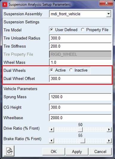
About Dual Wheels:
The __MDI_SUSPENSION_TESTRIG test rig allows you to model dual tires (wheels) in your suspension assembly.
You can activate or deactivate dual wheels through Set Suspension Parameters dialog box from Simulate > Suspension Analysis > Set Suspension Parameters.
The "Dual Wheel Offset" field is used to specify the lateral offset for the placement of the outside wheel from inside wheel center. The mass, inertia and tire properties (that is, tire radius, stiffness and so on) of the inside wheel part (tire) will be set to the outside wheel part (tire).
When dual wheels are active, tire forces (reactions) gets distributed on inside and outside wheels.
Structure of Suspension Test Rig
You assemble your suspension and steering subsystems with the suspension test rig. Then, using the resulting assembly, you simulate different suspension motions and loadcases to determine how your suspension performs. To help you to assess the performance of your suspension, Adams Car calculates about forty characteristics, such as toe angle, camber angle, caster trail, roll center height, and aligning torque camber compliance.
When you assemble your suspension subsystem to the suspension test rig, the suspension arms, struts, links, and subframe that normally mount to the body, mount to ground. The test rig includes wheels and tires that mount to the suspension hubs. The test rig drives the suspension motion by tables that contact the tires, pushing the suspension up through the tires. Finally, if you include a steering subsystem, the test rig couples to the rack and the steering wheel to drive steering motion.
When you submit a suspension analysis you can request the test rig to control the wheel center or the tire contact patch positions. In some cases the test rig may not be able to achieve a desired position because the suspension travel is limited, for example, by a bumper. In such a case, the vertical actuators saturate, meaning they reach the maximum force they can apply. The forces and displacements the test rig can apply to the suspension through the vertical actuators are limited to reasonable values for passenger cars. For other vehicles, you may need to update the limits. To learn how to update the limits, see Vertical Actuators.
To properly assemble with the test rig, your suspension template must include the following output communicators (see Communicator Entity Class):
■suspension_mount (communicator entity class: mount) - Points to the parts (typically the hub, also known as the spindle) in your suspension template to which the test rig wheel tires mount.
■wheel_center_location (communicator entity class: location) - Contains the wheel-center location that Adams Car uses to locate the test rig relative to the suspension.
■toe_angle and camber_angle (communicator entity class: parameter real) - Contain the static toe and camber angles that Adams Car uses to orient the test-rig wheels.
■suspension_upright (communicator entity class: mount) - Points to the suspension upright in your suspension template. The suspension test rig creates a perpendicular joint primitive between the suspension mount (that is, the hub) and the suspension upright to lock wheel rotation during suspension analyses.
The following make up the suspension test rig:
Vertical Actuators
The left and right vertical actuators apply forces to drive the test-rig tables, and in turn, the suspension, up and down. An integral controller computes the actuator force necessary to achieve the desired wheel center or contact patch positions. However, the forces in the actuators are limited by default to -22,000 N in rebound and 40,000 N in jounce.
The vertical actuators are standard joint force actuators (pairs of action-only translational forces). You can modify the force limits using the Adams Car Template Builder through the menus Build -> Actuator -> Joint Force -> Modify.
Suspension Test Rig Tire
The suspension test rig includes left and right wheel and tire UDE instances that are compatible with Adams Tire. The test rig tables contact these tires to drive the suspension's vertical travel. These tires also apply the contact patch loads (read from the loadcase spline) to the suspension. The suspension test rig sets the simulation type string to ”SUSPENSION” to inform Adams Tire you are performing a suspension analysis.
About RIGID_WHEEL and LIVE_TIRE
When working with these tires you can modify them to select either of the following:
■RIGID_WHEEL - The tire transmits both compression and tension force allowing the test rig to pull the suspension into rebound.
■LIVE_TIRE - The tire only transmits compression force. Thus when the vertical force between the tire and table goes to zero, the tire separates from the table. Therefore, when using a LIVE_TIRE, the test rig cannot pull the suspension into rebound. However, the force of gravity and the suspension spring will typically drive the suspension into rebound until the suspension hits the rebound bumper.
For the equations for RIGID_WHEEL and LIVE_TIRE,
■radius is the distance, measured in the plane of the wheel, from the wheel center to the contact patch
■r is the unit vector directed from the contact patch to the wheel center
■n is the unit vector normal to the table
RIGID_WHEEL
When you select RIGID_WHEEL, you enter the tire stiffness and unloaded radius. Adams Car sets the tire property file string to ”RIGID_WHEEL” and passes the stiffness and radius you entered to Adams Tire through an ARRAY statement. Adams Tire calculates the tire vertical force using the following equation:
force = tire_stiffness*(unloaded_radius - radius) (r o n)
LIVE_TIRE
When you select LIVE_TIRE, you must enter a tire property file. Adams Tire opens the property file and reads the unloaded radius and vertical stiffness. These values are automatically converted to the proper units for your suspension assembly. Other parameters in the tire property file are ignored. Adams Tire calculates the tire vertical force using the following equation:
force = max(0.0, tire_stiffness*(unloaded_radius - radius) (r o n))
Static Loads
You can specify forces, torques, and displacements as inputs to your suspension analyses. These inputs are stored in the loadcase spline. The loadcase spline contains a linear interpolation at discrete time intervals, between the upper and lower values.
The following table shows how forces and torques are expressed in the reference frames :
Forces/Torques in Reference Frames
Force/torque: | Reference frame: | |
|---|---|---|
TYDEX H ISO-W contact patch | TYDEX-C axis system wheel center | |
Lateral force (cornering) | x | |
Longitudinal force (braking) | x | |
Longitudinal force (traction) | x | |
Overturning moment | x | |
Rolling resistance torque | x | |
Aligning torque | x | |
Loadcase Files
Adams Car supports old suspension loadcase files (version 5) as follows:
■Vertical Mode = Length - Corresponds to wheel_center_height
■Vertical Mode = Force - Corresponds to an open-loop vertical force