Output of Suspension Analyses
Adams Car analyses output the following general suspension characteristics for all suspensions. To learn more about different characteristics, see section Computation of Suspension and Steering Characteristics.
For steered suspensions, Adams Car analyses also output the following steering characteriscs:
Aligning Torque - Steer and Camber Compliance
Note: | This help file is shared by several Adams products. |
Description | The aligning torque steer compliance is the change in steer angle due to unit aligning torque on the wheel. The aligning torque camber compliance is the change in camber angle due to a unit aligning torque on the wheel. A positive aligning torque acts to steer the wheel to the left. For a positive steer angle, the wheel turns to the left. For a positive camber angle, the top of the wheel tilts away from the body. |
Units | Angle/(Force*Length) |
Request Names | ■alt_steer_compliance.left ■alt_steer_compliance.right ■alt_camber_compliance.left ■alt_camber_compliance.right |
Method | alt_steer_compliance.left = C(6,6) + C(6,12) alt_steer_compliance.right = C(12,6) + C(12,12) alt_camber_compliance.left = C(4,6) + C(4,12) alt_camber_compliance.right= -C(10,6) + C(10,12)  Figure 1 Aligning Torque Loading for Steer and Camber Compliances |
Camber Angle
Note: | This help file is shared by several Adams products. |
Description | Camber angle is the angle the wheel plane makes with respect to the vehicle's vertical axis. It is positive when the top of the wheel leans outward from the vehicle body. Note that the inclination angle, a measurement available in full-vehicle analyses, is the angle the wheel plane makes with respect to the road surface. The inclination angle is used for tire calculations. |
Units | Angle |
Request Names | ■camber_angle.left ■camber_angle.right |
Inputs | Wheel-center axis (spin axis) unit vectors, left and right |
Method | camber_angle = -arcsin  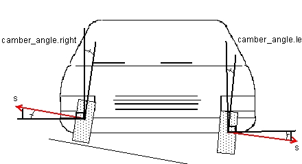 Figure 2 Camber Angle |
Caster Angle
Note: | This help file is shared by several Adams products. |
Description | Caster angle is the angle in the side elevation (vehicle XZ plane) between the steering (kingpin) axis and the vehicle's vertical axis. It is positive when the steer axis is inclined upward and rearward. Adams computes the steer axis using the geometric or instant axis method. |
Units | Angle |
Request Names | ■caster_angle.left ■caster_angle.right |
Inputs | ■Steer (kingpin) axis unit vectors - left and right ■Road vertical unit vector (z) ■Road longitudinal unit vector (x) |
Method | Adams uses the direction cosines in the x- and the z-directions of the kingpin axis to calculate caster angle, such that: sx = steer_axis road_x_axis sz = steer_axis road_z_axis caster_angle = rtod * arctan(sx/sz)  Figure 3 Caster Angle |
Dive Braking/Lift Braking
Note: | This help file is shared by several Adams products. |
Description | Dive braking is the amount of front suspension compression per G of vehicle braking. Included in dive is suspension compression due to weight transfer plus suspension extension due to brake forces. Positive dive indicates that the front suspension compresses in braking. Lift braking is the amount of rear suspension extension per G of vehicle braking. Included in lift is suspension extension due to weight transfer plus compression due to brake forces. Positive lift indicates that the rear suspension extends in braking. |
Units | Length/g |
Request Names | ■dive.left ■dive.right |
Inputs | ■Compliance matrix ■Fraction of braking applied at this axle ■Loaded tire radius ■Tire stiffness ■Whole vehicle CG height ■Total vehicle weight ■Wheelbase |
Method | Adams first computes the longitudinal force percentage due to braking: Fleft = Fright = Brake Ratio / 2.0 and then the vertical force percentange due to weight transfer: Wleft = Wright = Whole vehicle CG height/ (2 x Wheelbase) For rear anti-lift, the weight transfer is a negative value. These are forces at each wheel per unit total braking force. Vertical deflections due to the vertical force are: Zwleft = Wleft x C(3,3) + Wright x C(3,9) Zwright = Wleft x C(9,3) + Wright x C(9,9) Vertical deflections due to tractive forces are as follows, where Rl is the loaded radius of the tire: ZFleft = Fleft [C(3,1) - Rl x C(3,5)] + Fright[C(3,7) - Rl x C(3,11)] ZFright = Fleft [C(9,1) - Rl x C(9,5)] + Fright[C(9,7) - Rl x C(9,11)] The dive is: dive.left = (ZFleft + ZWleft + Wleft / Kt) Vehicle Weight dive.right = (ZFright + ZWright + Wright / Kt) Vehicle Weight |
Fore-Aft Wheel Center Stiffness
Note: | This help file is shared by several Adams products. |
Description | The stiffness of the suspension in the fore-aft direction is relative to the body, measured at the wheel center. |
Units | Force/Length |
Request Names | ■fore_aft_wheel_center_stiffness.left ■fore_aft_wheel_center_stiffness.right |
Inputs | Compliance matrix |
Method | Adams applies equal unit forces acting longitudinally at the wheel centers. It calculates the fore-aft wheel center stiffness as follows: fore_aft_wheel_center_stiffness.left = 1 / C(1,1) fore_aft_wheel_center_stiffness.right = 1 / C(7,7) |
Front-View Swing Arm Length and Angle
Note: | This help file is shared by several Adams products. |
Description | The swing arm is the imaginary arm extending from the wheel's front elevation instant center of rotation to the wheel center. The swing arm has a positive length when the instant center is inward of the wheel center. The angle of the swing arm is the angle it makes to the horizontal. A positive angle is when the arm slopes outward and upward from the center of rotation to the wheel center. The magnitude of the swing-arm length is limited to a maximum of 1000 meters. |
Units | Length; Angle |
Request Names | ■fr_view_swing_arm_angle.left ■fr_view_swing_arm_angle.right ■fr_view_swing_arm_length.left ■fr_view_swing_arm_length.right |
Inputs | Compliance matrix |
Method | The change in vertical and lateral position and the front view rotation of the left wheel center due to a unit vertical force at the left wheel center is:    The left front view swing arm length and angle are: fr_view_swing_arm_length.left =  fr_view_swing_arm_angle.left =  The change in vertical and lateral position and the front view rotation of the right wheel center due to a unit vertical force at the right wheel center is:    |
The right front view swing arm length and angle are: fr_view_swing_arm_length.right =  fr_view_swing_arm_angle.right =  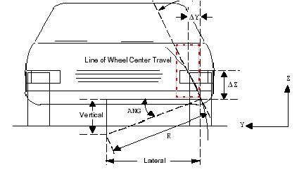 Figure 4 Instant Center Front View (Lateral, Vertical) |
Kingpin Inclination Angle
Note: | This help file is shared by several Adams products. |
Description | The kingpin inclination angle is the angle in the front elevation between the steer axis (the kingpin axis) and the vehicle's vertical axis. It is positive when the steer axis is inclined upward and inward. |
Units | Angle |
Request Names | ■kingpin_incl_angle.left ■kingpin_incl_angle.right |
Inputs | Kingpin axis unit vectors - left and right |
Method | Adams uses the direction cosines in the y-direction and the z-direction of the kingpin axis to calculate the kingpin inclination angle: kingpin_incl_angle.left =  kingpin_incl_angle.right =   Figure 5 Kingpin Angle (Ø is the Kingpin Angle) |
Kingpin Location
Note: | This help file is shared by several Adams products. |
Description | The kingpin location is the location in global coordinates of a point on the wheel part that does not translate when steered about the kingpin axis. |
Units | Length |
Request Names | ■kingpin_location.left_X ■kingpin_location.left_Y ■kingpin_location.left_Z ■kingpin_location.right_X ■kingpin_location.right_Y ■kingpin_location.right_Z |
Inputs | ■Compliance matrix or kingpin axis markers ■Wheel center position |
Method | Adams uses one of two methods to compute the kingpin location. Ideally, if the user selects the Steer Axis Calculation method Instant Axis, Adams will use the compliance matrix to find the kingpin location. This method uses a small steering input and finds the location on the wheel that doesn’t translate when steering about the kingpin axis. T = wheel center translation vector A = wheel center orientation vector R = vector from wheel center to kingpin axis wcpos = wheel center position kpps = kingpin position A point on the kingpin axis will not translate due to a steer input. To find this point relative to the wheel center, compute a radius vector from the wheel center to the kingpin axis such that: 0 = T + R X A Solving this equation for R yields: R = -T X A / (|A|*|A|) To locate the Kingpin axis add R to the wheel center position: kppos = wcpos + R Alternatively, if the user selects the Steer Axis Calculation method Geometric, Adams will use the I Coordinate Reference as the kingpin location. This method relies on the user to select an appropriate location. Due to suspension compliance, the resulting location may be slightly different than the input location. |
Lateral Force - Deflection, Steer, and Camber Compliance
Note: | This help file is shared by several Adams products. |
Description | The deflections at the wheel center due to unit lateral forces applied simultaneously at the tire contact patches. The forces are oriented as if in a right turn. Adams reports the lateral translational deflection, steer deflection (rotational deflection about the vertical axis), and the camber deflection (rotational deflection about the longitudinal axis). Positive deflection indicates a deflection to the right. Positive steer is a steer to the left. Positive camber compliance is when the wheels lean outward at the top. |
Units | Deflection - length; Camber and steer - angle |
Request Names | ■lat_force_defl_compliance.left ■lat_force_defl_compliance.right ■lat_force_steer_compliance.left ■lat_force_steer_compliance.right ■lat_force_camber_compliance.left ■lat_force_camber_compliance.right |
Inputs | ■Compliance matrix ■Tire radius - loaded |
Method | When the force is applied at the tire contact patch, Adams computes the deflection due to both the lateral force at the wheel center and the moment created around the wheel center. The total compliances are: lat_force_defl_compliance.left = +[C(2,2) + Rl x C(2,4) + C(2,8) + Rl x C(2,10)] lat_force_defl_compliance.right = +[C(8,2) + Rl x C(8,4) + C(8,8) + Rl x C(8,10)] lat_force_steer_compliance.left = +[C(6,2) + Rl x C(6,4) + C(6,8) + Rl x C(6,10)] lat_force_steer_compliance.right = +[C(12,2) + Rl x C(12,4) + C(12,8) + Rl x C(12,10)] lat_force_camber_compliance.left = +[C(4,2) + Rl x C(4,4) + C(4,8) + Rl x C(4,10)] lat_force_camber_compliance.right = -[C(10,2) + Rl x C(10,4) + C(10,8) + Rl x C(10,10)]  Figure 6 Lateral Force Loading for Deflection, Steer, and Camber Compliances |
Lift/Squat Acceleration
Note: | This help file is shared by several Adams products. |
Description | Lift is the amount of front suspension extension (rebound) per G of vehicle acceleration. Squat is the amount of rear suspension compression (jounce) per G of vehicle acceleration. Lift and squat arise when the suspension reacts to longitudinal tractive forces, weight transfer forces, and, in dependent suspensions, to the differential input and output torques. |
Units | Length/g |
Request Names | Front suspensions: ■lift.left ■lift.right Rear suspensions: ■squat_acceleration.left ■squat_acceleration.right |
Inputs | Compliance matrix Suspension parameters array: ■suspension_type (independent/dependent) Vehicle parameters array: ■sprung_mass ■cg_height ■wheelbase ■loaded_tire_radius ■tire_stiffness ■axle_ratio (final drive ratio, pinion ring gear ratio) ■drive_ratio (fraction of total drive torque directed to the suspension) Suspension geometry: ■Track Acceleration due to gravity (Ag) |
Method | The longitudinal force for unit tractive forces at the tire contact patches are: Fleft = Fright = -drive_ratio / 2.0 The vertical forces at the tire contact patch due to weight transfer are: VWleft = VWright = - cg_height / (2 * Wheelbase) Live axles also react with the drive torques (input torque to the differential pinion and output torque from the differential). Given the longitudinal tractive forces, the input torque (TI) to the differential is: TI = tire_loaded_radius * abs(Fleft + Fright) / axle_ratio And the vertical force at the tire contact patches due to the drive torque is: VTleft = -VTright = TI / Track Independent suspensions do not react to the drive torque. Therefore, VTleft = VTright = 0 The total vertical forces due to weight transfer and axle torque are: Vleft = VWleft + VTleft Vright = VWright + VTright These are all forces at each wheel per unit total acceleration force. Vertical deflections of the suspension due to total vertical forces ZWleft t = Vleft C( 3,3 ) + Vright C( 3,9 ) ZWright = Vleft C( 9,3 ) + Vright C( 9,9 ) The vertical deflections of the suspension due to tractive forces are ZFleft = Fleft [C( 3,1 ) - Tire_loaded_radius *C( 3,5 )] + Fright [C( 3,7 ) - Tire_loaded_radius *C( 3,11 )] ZFright = Fleft [C( 9,1 ) - Tire_loaded_radius *C( 9,5 )] + Fright [C( 9,7 ) - Tire_loaded_radius *C( 9,11 )] For Independent suspensions the drive torque is not reacted by the Suspension, so ZFleft = Fleft [C( 3,1 )] + Fright [C( 3,7 )] ZFright = Fleft [C( 9,1 )] + Fright [C( 9,7 )] |
The left and right percent anti-lift for front suspensions and percent anti-squat for rear suspensions are: anti_lift.left / anti_squat.left = 100 * ZFleft / ZWleft anti_lift.right / anti_squat.right =100 *ZFright / ZWright Finally, the lift/squat per G of acceleration is: lift.left / squat_acceleration.left = (ZFleft + ZWleft +(Vleft/tire_stiffness)) * sprung_mass * Ag lift.right / squat_acceleration.right = (ZFright + ZWright+ (Vright / tire_stiffness)) * sprung_mass * Ag |
Percent Anti-Dive Braking/Percent Anti-Lift Braking
Note: | This help file is shared by several Adams products. |
Description | Percent anti-dive braking for a front suspension and percent anti-lift braking for a rear suspension are the ratio of vertical suspension deflections caused by braking forces and torques to the deflections caused by weight transfer. During braking, the vertical deflections in a suspension from weight transfer can, in part, be cancelled by the vertical deflections caused by braking forces and torques in the suspension. Suspensions that exhibit this characteristic are said to have anti-dive or anti-lift geometry. For front suspensions, percent anti-dive braking is positive when deflections caused by braking forces and torques act to extend or rebound the suspension. For rear suspensions, percent anti-lift braking is positive when the deflections caused by the braking forces and torques act to compress or jounce the suspension. |
Units | % |
Request Names | Front suspensions: ■anti_dive_braking.left ■anti_dive_braking.right Rear suspensions: ■anti_lift.left ■anti_lift.right |
Inputs | Compliance matrix Vehicle parameters array: ■sprung_mass ■cg_height ■wheelbase ■loaded_tire_radius ■tire_stiffness ■brake_ratio (fraction of braking done by the suspension) ■acceleration due to gravity (Ag) |
Method | The brake forces at the tire contact patch per G of longitudinal deceleration are: Fleft = Fright = sprung_mass * Ag * brake_ratio / 2 The brake torques reacted that the suspension reacts to are: BTleft = loaded_tire_radius * Fleft BTright = loaded_tire_radius * Fright The weight transfer forces that the suspension reacts to are: WTleft = sprung_mass * Ag * cg_height / wheelbase / 2 WTright = sprung_mass * Ag * cg_height / wheelbase / 2 The brake forces and torques that cause the suspension deflections are: ZBleft = Fleft * C(3,1) + Fright * C(3,7) + BTleft * C(3,5) + BTright * C(3,11) + Fleft / tire_stiffness ZBright = Fleft * C(9,1) + Fright * C(9,7) + BTleft * C(9,5) + BTright * C(9,11) + Fright / tire_stifness The weight transfer forces that cause the suspension deflections are: ZWleft = WTleft * C(3,3) + WTright * C(3,9) + WTleft / tire_stiffness ZWright = WTleft * C(9,3) + WTright * C(9,9) + WTright / tire_stiffness Finally, the percent anti-dive and percent anti-lift are: anti_dive_braking.left = anti_lift.left = 100 * ZBleft / ZWleft anti_dive_braking.right = anti_lift.right = 100 * ZBright / ZWright |
Percent Anti-Lift Acceleration/Percent Anti-Squat Acceleration
Note: | This help file is shared by several Adams products. |
Description | Percent anti-lift for a front suspension and percent anti-squat for a rear suspension are the ratio of vertical suspension deflections caused by tractive forces and drive torques to the deflections caused by weight transfer. During acceleration, the vertical deflections in a suspension from weight transfer can, in part, be cancelled by the vertical deflections caused by tractive forces and drive torques in the suspension. Suspensions that exhibit this characteristic are said to have anti-lift or anti-dive geometry. Note that a suspension that does not transmit tractive forces and drive torques (drive_ratio = 0.0) has zero anti-lift or anti-squat. For front suspensions, percent anti-lift is positive when deflections caused by tractive forces and drive torques act to compress or jounce the suspension. For rear suspensions, percent anti-squat is positive when the deflections caused by the tractive forces and drive torques act to extend or rebound the suspension. |
Units | % |
Request Names | Front suspensions: ■anti_lift.left ■anti_lift.right Rear suspensions: ■anti_squat.left ■anti_squat.right |
Inputs | Compliance matrix Suspension parameters array: ■suspension_type (independent/dependent) Vehicle parameters array: ■sprung_mass ■cg_height ■wheelbase ■loaded_tire_radius ■tire_stiffness ■axle_ratio (final drive ratio, pinion ring gear ratio) ■drive_ratio (fraction of total drive torque directed to the suspension) Suspension geometry: ■Track Acceleration due to gravity (Ag) |
Method | The longitudinal force for unit tractive forces at the tire contact patches are: Fleft = Fright = -drive_ratio / 2.0 The vertical forces at the tire contact patch due to weight transfer are: VWleft = VWright = - cg_height / (2 * Wheelbase) Live axles also react with the drive torques (input torque to the differential pinion and output torque from the differential). Given the longitudinal tractive forces, the input torque (TI) to the differential is: TI = tire_loaded_radius * abs(Fleft + Fright) / axle_ratio And the vertical force at the tire contact patches due to the drive torque is: VTleft = -VTright = TI / Track Independent suspensions do not react to the drive torque. Therefore, VTleft = VTright = 0 The total vertical forces due to weight transfer and axle torque are: Vleft = VWleft + VTleft Vright = VWright + VTright These are all forces at each wheel per unit total acceleration force. Vertical deflections of the suspension due to total vertical forces ZWleft t = Vleft C( 3,3 ) + Vright C( 3,9 ) ZWright = Vleft C( 9,3 ) + Vright C( 9,9 ) The vertical deflections of the suspension due to tractive forces are ZFleft = Fleft [C( 3,1 ) - Tire_loaded_radius *C( 3,5 )] + Fright [C( 3,7 ) - Tire_loaded_radius *C( 3,11 )] ZFright = Fleft [C( 9,1 ) - Tire_loaded_radius *C( 9,5 )] + Fright [C( 9,7 ) - Tire_loaded_radius *C( 9,11 )] For Independent suspensions the drive torque is not reacted by the Suspension, so ZFleft = Fleft [C( 3,1 )] + Fright [C( 3,7 )] ZFright = Fleft [C( 9,1 )] + Fright [C( 9,7 )] The left and right percent anti-lift for front suspensions and percent anti-squat for rear suspensions are: anti_lift.left / anti_squat.left = 100 * ZFleft / ZWleft anti_lift.right / anti_squat.right =100 *ZFright / ZWright |
Ride Rate
Note: | This help file is shared by several Adams products. |
Description | Ride rate is the spring rate of the suspension relative to the body, measured at the tire contact patch. |
Units | Force/Length |
Request Names | ■ride_rate.left ■ride_rate.right |
Inputs | ■Compliance matrix ■Tire stiffness |
Method | Adams computes ride rate as the equivalent rate of the wheel rate and tire rate in series. Ks = Wheel rate (see Wheel Rate) Kt = Vertical tire rate Ktotal = Ks x Kt / (Ks + Kt) |
Ride Steer
Note: | This help file is shared by several Adams products. |
Description | Ride steer is the slope of the steer angle versus the vertical wheel travel curve. Ride steer is the change in steer angle per unit of wheel center vertical deflection due to equal vertical forces at the wheel centers. Positive ride steer implies that the wheels steer to the right, as the wheel centers move upward. |
Units | Angle/length |
Request Names | ■ride_steer.left ■ride_steer.right |
Inputs | Compliance matrix |
Method | Change in Wheel Orientation Using the compliance matrix, Adams first calculates the change in wheel orientation (W) due to unit forces applied at both wheel centers: Wl/dF = C(4, 3) - C(4, 9) , C(5, 3) - C(5, 9) , C(6, 3) - C(6, 9) Wr/dF = C(10, 3) - C(10,9) , C(11, 3) - C(11, 9) , C(12, 3) - C(12,9) Change in Wheel-Center (Spin) Vector Orientation The change in the left wheel-center (spin) vector (d(wcvl)) and the right wheel (spin) vector (d(wcvr) are vectors of partial derivatives given by the cross product of the change in wheel orientation with the wheel-center vector: d(wcvl)/dF = Wl x wcvl d(wcvr)/dF = Wr x wcvr Change in Steer Angle The change in steer angle due to a change in wheel-center vector orientation is also a vector of partial derivatives given by: d(steer_anglel)/d(wcvl) = (-1.0 / ( syl**2 + sxl**2 ) ) { syl, -sxl, 0 } d(steer_angler)/d(wcvr) = (-1.0 / ( syr**2 + sxr**2 ) ) { syr, -sxr, 0 } where: sxl = wcvl o x; The x component of the left wheel-center (spin) vector syl = wcvl o y; The y component of the left wheel-center (spin) vector\sxr = wcvr o x; The x component of the right wheel-center (spin) vector syr = wcvr o y; The y component of the right wheel-center (spin) vector The change in steer angle due to unit vertical forces at both wheel centers is computed by the chain rule: d(steer_anglel) /dF = ( -d(steer_anglel)/d(wcvl) ) o ( d(wcvl) / dF ) d(steer_angler)/dF = ( -d(steer_angler)/d(wcvr) ) o ( d(wcvr) / dF ) |
Change in Wheel-Center Vertical Travel The change in wheel-center vertical travel (dz) due to unit vertical forces applied at both wheel centers is: dzl /dF = { C(3,3) + C(3,9) } dzr /dF = { C(9,3) + C(9,9) } Using the chain rule one final time, the ride steer is: ride_steer.left = d(steer_anglel)/dzl = d(steer_anglel)/dF/(dF/dzl) ride_steer.right = d(steer_angler)/dzr = d(steer_angler)/dF/(dF/dzr) | |
Nomenclature | ■Bold, uppercase text, such as Wl, are vectors. ■Bold, lowercase text, such as wcvl, are unit vectors. ■X is the vector cross product operator. ■o is the vector dot product operator. ■* is the scalar multiplication operator. |
Roll Camber Coefficient
Note: | This help file is shared by several Adams products. |
Description | Roll camber coefficient is the rate of change of wheel inclination angle with respect to vehicle roll angle. Positive roll camber coefficient indicates an increase in camber angle per degree of vehicle roll. |
Units | Unitless |
Request Names | ■roll_camber_coefficient.left ■roll_camber_coefficient.right |
Inputs | ■Compliance matrix ■Tire stiffness ■Track width |
Method | Adams applies opposing unit forces acting vertically at the tire contact patches. The height difference between the tire contact patches is the following, where Kt is the vertical tire rate: DZ = C(3,3) - C(3,9) - C(9,3) + C(9,9) + 2/Kt The vehicle roll angle is the rotation of the line through the tire contact patches: Av = DZ / track Adams measures the wheel inclination with respect to the line through the tire contact patches, which has two components. The first is from the vertical movement of the tire contact patch and is the same as the vehicle roll angle. The second is from the rotational compliance at the wheel center due to the vertical force: Ac = - C(4,3) + C(4,9) (left side) = - C(10,3) + C(10,9) (right side) The total wheel inclination is then: Ai = Av - Ac The roll camber is then: roll_camber_coefficient = (Av - Ac) / Av = 1 - Ac / Av  Figure 7 Roll Camber |
Roll Caster Coefficient
Note: | This help file is shared by several Adams products. |
Description | Roll caster coefficient is the rate of change in side view steer axis angle with respect to vehicle roll angle. A positive roll caster coefficient indicates an increase in caster angle per degree of vehicle roll. This calculation assumes that the steer axis (kingpin) is fixed in the suspension upright as in a double-wishbone or MacPherson strut suspension. The calculation, however, is not valid for suspensions where the steer axis is not fixed in the suspension upright, for example, a five-link front suspension used in Audi A4. |
Units | Unitless |
Request Names | ■roll_caster_coefficient.left ■roll_caster_coefficient.right |
Inputs | ■Compliance matrix ■Tire stiffness ■Track width |
Method | Adams applies opposing unit forces acting vertically at the tire contact patches. The height difference between the tire contact patches is the following, where Kt is the vertical tire rate: DZ = C(3,3) - C(3,9) - C(9,3) + C(9,9) + 2/Kt The vehicle roll angle is the rotation of the line through the tire contact patches: Av = DZ / track The rotational compliance at the wheel center due to the vertical force is: Ac = C(5,3) - C(5,9) (left side) = C(11,3) - C(11,9) (right side) The roll caster is then: roll_caster_coefficient = Ac / Av |
Roll Center Location
Note: | This help file is shared by several Adams products. |
Description | Roll center location is the point on the body where the moment of the lateral and vertical forces exerted by the suspension links on the body vanishes. |
Units | Length |
Request Names | ■roll_center_location.lateral_from_half_track ■roll_center_location.vertical ■roll_center_location.lateral_to_left_patch ■roll_center_location.lateral_to_right_patch |
Inputs | ■Compliance matrix at contact patches ■Contact patch location |
Method | Adams applies unit vertical forces (perpendicular to the road) at the tire contact and measures the resulting contact patch displacements in the vertical and lateral direction (front view). Adams projects lines perpendicular to the contact patch displacements for both the left and right patches. The roll center lies at the intersection of these lines. Adams reports errors when the motions of the left and right patches are parallel (just as it occurs with a fully trailing arm suspension). Therefore, the projected lines have no intersection. Adams also reports an error when the motion of the left and/or right patches is very small for a unit vertical force (for example, the suspension is very stiff). Finally, Adams limits the distance from the roll center to the left and right patches to +/- 1000 meters. 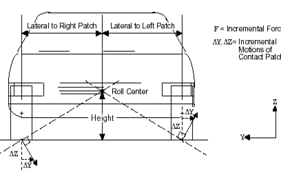 Figure 8 Roll Center Location (Front View) |
Roll Steer
Note: | This help file is shared by several Adams products. |
Description | Roll steer is the change in steer angle per unit change in roll angle, or the slope of the steer-angle-verses-roll-angle curve. Roll steer is positive when for increasing roll angle (left wheel moving up, right wheel moving down) the steer angle increases (wheels steer toward the left). |
Units | Unitless |
Request Names | ■roll_steer.left ■roll_steer.right |
Inputs | ■Wheel center spin axis unit vector (wcv) left and right ■Track ■Tire stiffness (Kt) ■Compliance matrix |
Method | Using the compliance matrix, Adams first calculates the change in roll angle and the change in the wheel-center vector orientation due to a roll moment (the roll moment is a unit vertical force upward at the left contact patch and a unit force downward at the right contact patch). Then, Adams calculates the change in steer angle due to the change in wheel-center vector orientation. Finally, Adams applies the chain rule to calculate the roll steer. Change in Roll Angle The change in roll angle is: d(roll_angle)/d(roll_moment) = ( C(3,3) - C(3,9) - C(9,3) + C(9,9) + 2.0/Kt ) / Track Change in Wheel-Center Spin Vector Orientation The changes in orientation of the left wheel (Wl) and of the right wheel (Wr) due to a unit upward force at the left contact patch and a unit downward force at the right contact patch are: Wl = { C(4, 3) - C(4, 9) , C(5, 3) - C(5, 9) , C(6, 3) - C(6, 9) } Wr = { C(10, 3) - C(10,9) , C(11, 3) - C(11, 9) , C(12, 3) - C(12, 9) } The change in the left wheel-center (spin) vector (d(wcvl)) and the right wheel (spin) vector (d(wcvr) are vectors of partial derivatives: d(wcvl)/d(roll_moment) = Wl x wcvl d(wcvr)/d(roll_moment) = Wr x wcvr Change in Steer AngleThe change in steer angle due to a change in wheel-center vector orientation is also a vector of partial derivatives given by: d(steer_anglel)/d(wcvl) = (-1.0 / ( syl**2 + sxl**2 ) ) { syl, -sxl, 0 } d(steer_angler)/d(wcvr) = (-1.0 / ( syr**2 + sxr**2 ) ) { syr, -sxr, 0 } where: sxl = wcvl o x; The x component of the left wheel-center (spin) vector syl = wcvl o y; The y component of the left wheel-center (spin) vector sxr = wcvr o x; The x component of the right wheel-center (spin) vector syr = wcvr o y; The y component of the right wheel-center (spin) vector |
The change in steer angle for a change in roll moment is computed using the chain rule: d(steer_anglel)/d(roll_moment) = ( d(steer_anglel)/d(wcvl) ) o ( d(wcvl)/d(roll_moment) ) d(steer_angler)/d(roll_moment) = ( d(steer_angler)/d(wcvr) ) o ( d(wcvr)/d(roll_moment) ) Roll SteerAnd applying the chain rule one last time, the roll steer is roll_steer.left = ( d(steer_anglel)/d(roll_moment) ) / ( d(roll_angle)/d(roll_moment) ) roll_steer.right = ( d(steer_angler)/d(roll_moment) ) / ( d(roll_angle)/d(roll_moment) ) | |
Request Statements | REQUST/id, FUNCTION=USER(900,17,characteristics_input_array_id) |
Nomenclature | ■Bold, uppercase text, such as Wl, are vectors. ■Bold, lowercase text, such as wcvl, are unit vectors. ■X is the vector cross product operator. ■o is the vector dot product operator. ■* is the scalar multiplication operator. |
Side-View Angle
Note: | This help file is shared by several Adams products. |
Description | The side-view angle is the wheel carrier side-view rotation angle. It is positive for a clockwise rotation, as seen from the left side of the vehicle. |
Units | Angle |
Request Names | ■side_view_angle.left ■side_view_angle.right |
Inputs | Wheel bearing I marker and origo_y |
Method | side_view_angle = az, marker I, marker J |
Side-View Swing Arm Length and Angle
Note: | This help file is shared by several Adams products. |
Description | The swing arm is an imaginary arm extending from the wheel's side elevation instant center of rotation to the wheel center. For front suspensions, the sign convention is that when the instant center is behind the wheel center, the swing arm has a positive length. For rear suspensions, the sign convention is the opposite: when the instant center is ahead of the wheel center, the swing arm has a positive length. The angle of the swing arm is the angle it makes to the horizontal. A positive angle for a positive length is when the arm slopes downward from the wheel center. A positive angle for a negative length arm is when the arm slopes upward from the wheel center. The magnitude of the swing-arm length is limited to a maximum of 1000 meters. |
Units | Length, Angle |
Request Names | ■side_view_swing_arm_angle.left ■side_view_swing_arm_angle.right ■side_view_swing_arm_length.left ■side_view_swing_arm_length.right |
Inputs | Compliance matrix |
Method | The change in vertical and longitudinal position and the side view rotation of the left wheel center due to a unit vertical force at the left wheel center is: DX left = C(1,3) DZ left = C(3,3) DØ left = C(5,3) The left side view swing arm length and angle are: side_view_swing_arm_length.left = (DX left 2 + DZ left 2)1/2 / DØ left side_view_swing_arm_angle.left = tan-1 (DX left / DZ left) The change in vertical and longitudinal position and the change in side view rotation of the right wheel center due to a unit vertical force at the right wheel center is: DX right = C(7,9) DZ right = C(9,9) DØ right = C(11,9) The right side view swing arm length and angle are: side_view_swing_arm_length.right = (DXright 2 + DZright 2) 1/2 / DØ right side_view_swing_arm_angle.right = tan-1 (DXright / DZ right) 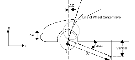 Figure 9 Instant Center Side View (Fore and Aft, Vertical) |
Suspension Roll Rate
Note: | This help file is shared by several Adams products. |
Description | Suspension roll rate is the torque, applied as vertical forces at the tire contact patches, per degree of roll, measured through the wheel centers. |
Units | Force-Length/Angle |
Request Names | ■susp_roll_rate.suspension_roll_rate |
Inputs | ■Compliance matrix ■Track width |
Method | Adams uses opposing unit forces as the applied torque: T = F x track = track The resulting vertical distance between wheel centers is:  The rotation of the line through the wheel centers is:  The roll rate is: susp_roll_rate = T / Ø =   Figure 10 Roll Rate - Suspension |
Toe Angle
Note: | This help file is shared by several Adams products. |
Description | Toe angle is the angle between the longitudinal axis of the vehicle and the line of intersection of the wheel plane and the vehicle's XY plane. Adams reports toe angle in radians. It is positive if the wheel front is rotated in towards the vehicle body. |
Units | Angle |
RequestNames | ■toe_angle.left ■toe_angle.right |
Inputs | Wheel center axis unit vectors - left and right |
Method | Adams uses the direction cosines in the x- and y-directions of the wheel center axis relative to the road to calculate toe angle, such that: toe_angle.left = tan-1 (DCOSX/DCOSY) toe_angle.right = tan-1 (-DCOSX/DCOSY)  Figure 11 Toe Angle |
Total Roll Rate
Note: | This help file is shared by several Adams products. |
Description | Total roll rate is the torque, applied as vertical forces at the tire contact patches, per degree of roll, measured at the tire contact patches. |
Units | Force-Length/Angle |
Request Names | ■total_roll_rate.left ■total_roll_rate.right |
Inputs | ■Compliance matrix ■Tire stiffness ■Track width |
Method | Adams uses opposing unit forces as the applied torque: T = F x track = track The resulting vertical distance between wheel centers is the following, where Kt is the tire stiffnesses:  The rotation of the line through the tire contact patches is:  The roll rate is: total_roll_rate = T/Ø =  |
Total Track
Note: | This help file is shared by several Adams products. |
Description | Total track is the distance measured along the line passing through the left and right tire contact points with the left and right road parts (pads) and then projected onto the right road plane. The tire contact point lies at the intersection of two lines: ■The first line is formed by the intersection of the wheel plane with the road plane. ■The second line is perpendicular to the first and passes through the wheel center. The wheel plane is perpendicular to the wheel spin axis and passes through the wheel center. The left and right road planes behave differently, depending on your coordinates: ■In vehicle coordinates, the left and right road planes remain perpendicular to the vehicle's vertical axis, but lie at different heights. If you run an opposite wheel-travel using vehicle coordinates, the left and right road planes remain un-rolled (flat) relative to the vehicle body (ground in a suspension analysis). ■In ISO coordinates, the left and right road planes form one plane that rotates about the vehicle's longitudinal axis to simulate rolling of the suspension relative to the road. If you run an opposite wheel-travel analysis using ISO coordinates, the right road plane and left road plane are identical, as if the suspension was rolled relative to a flat road. The total_track (distance between tire contact points) projected onto the right road plane is foreshortened, and therefore, is less than the total track output. Also, the distance from the road plane to the wheel center depends on the tire deflection, which depends on the tire stiffness and the force required to deflect the suspension to a given position. |
Units | Length |
Request Names | ■total_track |
Inputs | ■Contact patch positions |
Method | The following is the equation used to compute total track: T = ABS (ROAD (COMP, CPPLEFT) - ROAD (COMP, CPPRIGHT)) where: ■ROAD is a data structure filled with a series of kinematic characteristics of the suspension. ROAD (Y,CPPLEFT) returns, for example, the Y component of the left contact patch position. ■CPP represents the instantaneous coodinates of contact points obtained as described above. |
Wheel Rate
Note: | This help file is shared by several Adams products. |
Description | Wheel rate is the vertical stiffness of the suspension relative to the body, measured at the wheel center. |
Units | Force/Length |
Request Names | ■wheel_rate.left ■wheel_rate.right |
Inputs | Compliance matrix |
Method | Adams computes suspension wheel rate as the inverse of the z-axis displacement at the wheel center due to the vertical forces applied at both wheel centers simultaneously. wheel_rate.left = 1 / (C(3,3) + C(3,9)) wheel_rate.right = 1 / (C(9,3) + C(9,9)) |
Ackerman
Note: | This help file is shared by several Adams products. |
Description | Ackerman is the difference between the left and right wheel steer angles. A positive Ackerman indicates that the right wheel is being steered more to the right than to the left. |
Units | Angle |
Request Names | ■ackerman.left ■ackerman.right |
Inputs | Steer angle (see Steer Angle) |
Method | Adams Car computes Ackerman by subtracting the right steer angle from the left steer angle: ackerman = Right steer angle – Left steer angle |
Ackerman Angle
Note: | This help file is shared by several Adams products. |
Description | Ackerman angle is the angle whose tangent is the wheel base divided by the turn radius. Ackerman angle is positive for right turns. |
Units | Angle |
Request Names | ■ackerman_angle.left ■ackerman_angle.right |
Inputs | ■Turn radius (see Turn Radius) ■Wheelbase |
Method | ackerman_angle = tan-1(Wheel Base/Turn Radius)  Figure 12 Ackerman Angle |
Ackerman Error
Note: | This help file is shared by several Adams products. |
Description | Ackerman error is the difference between the steer angle and the ideal steer angle for Ackerman geometry. Because Adams Car uses the inside wheel to compute the turn center, the Ackerman error for the inside wheel is zero. For a left turn, the left wheel is the inside wheel and the right wheel is the outside wheel. Conversely, for a right turn, the right wheel is the inside wheel and the left wheel is the outside wheel. Positive Ackerman error indicates the actual steer angle is greater than the ideal steer angle or the actual is steered more to the right. |
Units | Angle |
Request Names | ■ackerman_error.left ■ackerman_error.right |
Inputs | ■Steer angle (see Steer Angle) ■Ideal steer angle (see Ideal Steer Angle) |
Method | ackerman_error.left = (left steer angle - left ideal steer angle) ackerman_error.right = (right steer angle - right ideal steer angle) |
Caster Moment Arm (Mechanical Trail)
Note: | This help file is shared by several Adams products. |
Description | Caster moment arm is the distance from the intersection of the kingpin (steer) axis and the road plane to the tire contact patch measured along the intersection of the wheel plane and road plane. Caster moment arm is positive when the intersection of the kingpin axis and road plane is forward of the tire contact patch. |
Units | Length |
Request Names | ■caster_moment_arm.left ■caster_moment_arm.right |
Inputs | ■Kingpin axis position, a point on the kingpin axis (Rs) - left and right ■Kingpin (steer) axis unit vector (s) - left and right ■Tire contact patch position (Rp) - left and right ■Wheel center axis unit vector (w) - left and right ■The road normal unit vector (k) |
Methods | Adams Car first finds the intersection of the kingpin axis and the road plane. Note that by convention, the kingpin axis unit vector is directed upward, away from the road, and the road plane has zero height. The intersection of the kingpin axis and the road plane (Rkr) is: Rsr = Rs - (Rs o k)/(s o k) s Next, Adams Car finds a unit vector (l) directed rearward along the line of intersection between the wheel plane and the road plane: l = k x w / | k x w | (left side) l = k x -w / | k x -w | (right side) The distance along l from the contact patch to the intersection of the kingpin axis and the road plane is: caster_moment_arm = (Rp - Rkr) o l  Figure 13 Caster Moment Arm and Scrub Radius |
Ideal Steer Angle
Note: | This help file is shared by several Adams products. |
Description | Ideal steer angle is the steer angle in radians that gives Ackerman steer geometry or 100% Ackerman. For Ackerman steer geometry, the wheel-center axes for all four wheels pass through the turn center. Note that Adams Car uses the steer angle of the inside wheel to determine the turn center for Ackerman geometry. Therefore, the ideal steer angle and the steer angle are equal for the inside wheel. When making a left turn, the left wheel is the inside wheel. Conversely, when making a right turn, the right wheel is the inside wheel. A positive steer angle indicates a steer to the right. |
Units | Angle |
Request Names | ■ideal_steer_angle.left ■ideal_steer_angle.right |
Inputs | ■Turn radius (see Steer Angle) ■Tire contact patch position (Rp) - left and right ■Wheelbase |
Method | ideal_steer_angle.left = tan-1 [Wheel Base/(Turn Radius - Rp(left))] ideal_steer_angle.right = tan-1 [Wheel Base/(Turn Radius -Rp(right))] |
Note | ■Right turns give positive angles and turn radii ■Rp(left) < 0 ■Rp(right) > 0 ■|Inside wheel's ideal steer angle| > |outside wheel's ideal steer angle| |
Outside Turn Diameter
Note: | This help file is shared by several Adams products. |
Description | Outside turn diameter is the diameter of the circle defined by a vehicle's outside front tire when the vehicle turns at low speeds. Adams Car determines the circle by the tire's contact patch for a given steer angle. For a left turn, the right front wheel is the outside wheel. For a right turn, the left front wheel is the outside wheel. |
Units | Length |
Request Names | ■outside_turn_diameter.left ■outside_turn_diameter.right |
Inputs | ■Turn radius (see Turn Radius) ■Track width ■Wheelbase |
Method | outside_turn_radius = 2.0 [(| Turn Radius | +Track/2)2 + (Wheel Base) 2]1/2 |
Percent Ackerman
Note: | This help file is shared by several Adams products. |
Description | Percent Ackerman is the ratio of actual Ackerman to ideal Ackerman expressed as a percentage. Percent Ackerman is limited to the range from -999% to 999%. Percent Ackerman is positive when the inside wheel's steer angle is larger than the outside wheel's steer angle. |
Units | % |
Request Names | ■percent_ackerman.left ■percent_ackerman.right |
Inputs | ■Steer angle (see Steer Angle) ■Ideal steer angle (see Ideal Steer Angle) ■Ackerman (see Ackerman) |
Method | ackerman = Right steer angle - Left steer angle ideal_ackerman = Right ideal steer angle - Left ideal steer angle percent_ackerman = 100 x Ackerman/Ideal Ackerman |
Scrub Radius
Note: | This help file is shared by several Adams products. |
Description | Scrub radius is the distance from the intersection of the kingpin (steer) axis and the road plane to the tire contact patch measured along the projection of the wheel-center axis into the road plane. Scrub radius is positive when the intersection of the kingpin axis and the road plane is inboard of the tire contact patch. |
Units | Length |
Request Names | ■scrub_radius.left ■scrub_radius.right |
Inputs | ■Kingpin axis position (Rs) - left and right ■Kingpin (steer) axis unit vector (s) - left and right ■Tire contact patch position (Rp) - left and right ■Wheel-center axis unit vector (w) - left and right ■The road normal unit vector (k) |
Method | Adams Car first finds the intersection of the kingpin axis and the road plane. Note that by convention the kingpin axis unit vector is directed upward, away from the road, and the road plane has zero height. The intersection of the kingpin axis and the road plane (Rkr) is: Rsr = Rs - (Rs o k)/(s o k) s Next Adams Car finds the projection (m) of the wheel-center axis (w) onto the road plane M = (k x w) x k m = M / | M | The distance from the contact patch to the intersection of the kingpin axis and the road plane along m is: scrub_radius = (Rp - Rkr) o m Figure 14 Caster Moment Arm and Scrub Radius |
Steer Angle
Note: | This help file is shared by several Adams products. |
Description | Steer angle is the angle measured from the vehicle heading to the line formed by the intersection of the wheel plane with the ground plane. Steer angle is positive when a wheel is rotated to the right as if the vehicle were making a right turn. |
Units | Angle |
Request Names | ■steer_angle.left ■steer_angle.right |
Inputs | Wheel-center axis unit vectors - left and right |
Method | Adams Car uses the direction cosines of the x-direction and the y-direction of the wheel-center axis constructed from the wheel-center orientation to calculate steer angle: steer_angle.left = tan-1 (-DCOSX/|DCOSY|) steer_angle.right = tan-1 (DCOSX/|DCOSY|) |
Steer Axis Offset
Note: | This help file is shared by several Adams products. |
Description | The steer axis offset is the shortest distance from the steer (kingpin) axis to the wheel center. The steer axis offset is measured in the plane perpendicular to the steer axis and passing through the wheel center. The steer axis offset is always positive. The steer axis offset-longitudinal is the component of the steer axis offset along the intersection of the wheel plane with the plane perpendicular to the steer axis and passing through the wheel center. The steer axis offset-longitudinal is positive when the wheel center is aft of the steer axis. The steer axis offset-lateral is the component of the steer axis offset along the projection of the wheel-center axis into the plane perpendicular to the steer axis and passing through the wheel center. The steer axis offset - lateral is positive when the wheel center lies outboard of the steer axis. |
Units | Length |
Request Names | ■steer_axis_offset.off_left ■steer_axis_offset.off_right ■steer_axis_offset.lon_left ■steer_axis_offset.lon_right ■steer_axis_offset.lat_left ■steer_axis_offset.lat_right |
Inputs | ■Wheel-center position (WCP) left and right ■Wheel-center (spin) axis unit vector (wcv) left and right ■Kingpin (steer) axis position (KPP) left and right ■Kingpin (steer) axis unit vector (kpv) left and right |
Method | First, define longitudinal and lateral directions in a plane perpendicular to the steer (kingpin) axis using the kingpin axis vector and the wheel-center (spin) vector. u_lon = ( wcv x kpv ) / | wcv x kpv | and: u_lat = ( kpv x u_lon ) / | kpv x u_lon | Note that u_lat is the projection of the wheel-center vector (wcv) onto the plane perpendicular to the kingpin axis. The displacement vector (R) from a point on the kingpin (steer) axis to the wheel center is: R = WCP - KPP The steer axis offset-longitudinal is: steer_axis_offset.lon_left = -R o u_lon steer_axis_offset.lon_right = R o u_lon The steer axis offset-lateral is: steer_axis_offset.lat_left = R o u_lat steer_axis_offset.lat_right = R o u_lat Finally, the steer axis offset is: steer_axis_offset.off_left = sqrt( lon_left2 + lat_left2 ) steer_axis_offset.off_right = sqrt( lon_right2 + lat_right2 ) 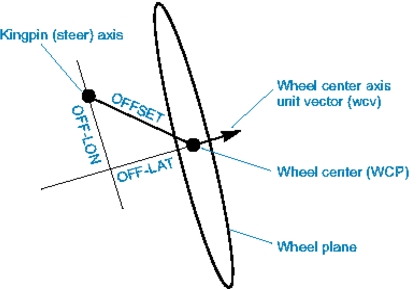 Figure 15 Steer Axis Offset (Top View) |
Request Statements | Offset:REQUST/id, FUNCTION=USER(900,44,characteristics_input_array_id)\ Longitudinal offset:REQUST/id, FUNCTION=USER(900,45,characteristics_input_array_id)\ Lateral offset:REQUST/id, FUNCTION=USER(900,46,characteristics_input_array_id)\ |
Nomenclature | ■Bold text in uppercase letters, such as R, shows vectors. ■Bold text in lowercase letters, such as u_lon, shows unit vectors. ■X is the vector cross product operator. ■o is the vector dot product operator. ■* is the scalar multiplication operator. |
Turn Radius
Note: | This help file is shared by several Adams products. |
Description | The turn radius is the distance measured in the ground plane from the vehicle center line to the turn center along the y-axis (see the figure for Ackerman Angle). Turn radius is positive for right turns and negative for left turns. |
Units | Length |
Request Names | ■turn_radius.left ■turn_radius.right |
Inputs | ■Steer angle (see Steer Angle) ■Track width ■Wheelbase ■Wheel-center orientations - left and right |
Method | Adams Car determines the inside wheel by checking the sign of the steer angles. It computes turn radius using the inside tire orientation. Left turn: turn_radius.left = - [Wheel Base (DCOSY/DCOSX) + Track/2] Right turn: turn_radius.right = [Wheel Base x (DCOSY/DCOSX) + Track/2] |