acar_shared database
Disc-Brake System
Overview
The disc-brake system template represents a device that applies resistance to the motion of a vehicle.
Figure 1 Disc-Brake System
Template name
_brake_system_4Wdisk
Major role
brake_system
Application
Full-vehicle Analysis to simulate the effect of braking on the dynamics of the vehicle.
Description
The disc-brake system template represents a simple model of a brake system. It applies a rotational torque between the caliper and the rotor.
Files referenced
None.
Topology
The caliper part is mounted to the suspension upright, while the rotor is mounted to the wheel. A rotational SFORCE is applied between the two parts.
Parameters
The toe and camber values that the suspension subsystem publishes define the spin axis orientation. In addition, the braking torque is expressed as a function of a number of parameters.
The following table lists the parameters in the template.
The parameter: | Takes the value: | Its units are: |
|---|---|---|
front_brake_bias | Real | No units |
front_brake_mu | Real | No units |
front_effective_piston_radius | Real | mm |
front_piston_area | Real | mm2 |
front_rotor_hub_wheel_offset | Real | mm |
front_rotor_hub_width | Real | mm |
front_rotor_width | Real | mm |
max_brake_value | Real | No units |
rear_brake_mu | Real | No units |
rear_effective_piston_radius | Real | mm |
rear_piston_area | Real | mm2 |
rear_rotor_hub_wheel_offset | Real | mm |
rear_rotor_hub_width | Real | mm |
rear_rotor_width | Real | mm |
Limitations
The disc-brake template is a simple model of a brake system. It does not model the complex interaction between the rotor and caliper.
Communicators
Mount parts provide the connectivity between the template and suspension subsystems. Input Communicators receive information about the toe and camber suspension orientation and the wheel-center location. Input to the brake system is brake demand.
The following table lists the communicators in the template.
The communicator: | Belongs to the class: | Has the role: |
|---|---|---|
ci[lr]_front_camber_angle | parameter_real | front |
ci[lr]_front_rotor_to_wheel | mount | front |
ci[lr]_front_toe_angle | parameter_real | front |
ci[lr]_front_wheel_center | location | front |
ci[lr]_front_suspension_upright | mount | front |
ci[lr]_rear_rotor_to_wheel | mount | rear |
ci[lr]_rear_suspension_upright | mount | rear |
ci[lr]_rear_toe_angle | parameter_real | rear |
ci[lr]_rear_camber_angle | parameter_real | rear |
ci[lr]_rear_wheel_center | location | rear |
cis_brake_demand | solver_variable | any |
cos_max_brake_value | parameter_real | inherit |
Notes: | The torque on the rotor depends on a number of parameters. The front right torque function is: T = 2 x PistonArea x BrakeLinePressure x µ x EffectivePistonRadius x STEP where: ■BrakeLinePressure is calculated as follows: BrakeLinePressure = BrakeBias * BrakeDemand * 0.1 where: ■BrakeBias defines the front and rear proportioning of the brake line pressure. Note that although the term is constant, in reality, simple hydraulic systems allow dynamic front and rear proportioning of the brake pressure depending on a number of factors, including longitudinal slip angle of the tires and dynamic load transfer. ■BrakeDemand is the force on the pedal (N) as it is output from the analysis. ■0.1 is a conversion factor that converts into pressure the force applied on the pedal. ■STEP is the function of the rotation of the rotor to wheel and suspension upright markers. The function prevents backward spinning of the wheels. STEP is a simple function that measures the WZ rotation of the marker on the rotor with respect to the marker on the upright and reverses the sign of the applied torque if the wheel is spinning backward. |
Double-Wishbone Suspension
Overview
A double-wishbone suspension is one of the most common suspension designs. It uses two lateral control arms to hold the wheel carrier and control its movements.
Figure 2 Double-Wishbone Suspension
Template name
_double_wishbone
Major role
Suspension
Application
Suspension and full-vehicle assemblies
Description
The double-wishbone template represents the most common design for doublewishbone suspensions. You can use the template as a front steerable suspension or as a rear non-steerable suspension.
You can set subsystems based on this template to kinematic or compliant mode. In kinematic mode, Adams Car replaces the bushings that connect the control arms to the body mount part with a corresponding purely kinematic constraint. Adams Car also does this for the top mount and lower strut mount.
You can deactivate the subframe part, as well as the halfshafts. A spring acts between the upper mount part and the lower strut. A bumpstop acts between the upper and lower strut parts.
The tierod parts are split to support toe adjusters; the lower control arms have a lateral sliding extension to support camber adjusters.
Files referenced
Bushings, springs, dampers, and bumpstops property files
Topology
The lower wishbone connects to a subframe or to the mount if you've deactivated the subframe. The upper wishbone connects to the body mount part. A spherical joint constrains the upright part to the upper and lower arms.
A spherical joint also connects the tie rods to the uprights. Tie rods attach to mount parts through convel joints. Convel joints also connect the tripots to the drive shafts. A static rotation control actuator locks the rotational degree of freedom of the hub during quasi-static analyses.
The joint: | Connects the part: | To the part: |
|---|---|---|
jklrev_lca | gel_lower_control_arm | ges_subframe |
jolsph_lca_balljoint | gel_upright | gel_lower_control_arm2 |
jolsph_tierod_outer | gel_tierod_outer | gel_upright |
jolcon_tierod_inner | gel_tierod_inner | mtl_tierod_to_steering |
josfix_subframe_rigid | ges_subframe | mts_subframe_to_body |
jklhoo_top_mount_kinematic | gel_upper_strut | mtl_strut_to_body |
jolsph_uca_balljoint | gel_upper_control_arm | gel_upright |
jolcyl_lwr_upr_strut | gel_lower_strut | gel_upper_strut |
jklrev_uca | gel_upper_control_arm | mtl_uca_to_body |
jklhoo_lwr_strut_kinematic | gel_lower_strut | gel_lower_control_arm |
joltra_tripot_to_differential | gel_tripot | mtl_tripot_to_differential |
jolcon_drive_sft_int_jt | gel_tripot | gel_drive_shaft |
jolcon_drive_sft_otr | gel_drive_shaft | gel_spindle |
joltra_lca_split | gel_lower_control_arm | gel_lower_control_arm2 |
joltra_tierod_split | gel_tierod_outer | gel_tierod_inner |
Hub Compliance on | ||
jolsph_hub_compliance | gel_spindle | gel_upright |
Hub Compliance off | ||
jolrev_spindle_upright | gel_spindle | gel_upright |
Parameters
Toe and camber variables define wheel spin axis, spindle part, and spindle geometry. The following table lists the parameters in the template.
The parameter: | Takes the value: | Its units are: |
|---|---|---|
phs_driveline_active | Integer | No units |
phs_kinematic_flag | Integer | No units |
pvs_hub_compliance_active | Integer | No units |
pvs_subframe_active | Integer | No units |
ph[lr]_toe_adjuster | Real | mm |
ph[lr]_camber_adjuster | Real | mm |
pv[lr]_toe_angle | Real | Degrees |
pv[lr]_camber_angle | Real | Degrees |
pv[lr]_drive_shaft_offset | Real | mm |
pvs_hub_compliance_offset | Real | mm |
Communicators
Mount parts provide connectivity from the template to body subsystems and the differential. Output Communicators publish toe, camber, steer axis, and wheel-center location information to the appropriate subsystems and the test rig. The following table lists the input and output communicators.
The communicator: | Belongs to the class: | Has the role: |
|---|---|---|
ci[lr]_ARB_pickup | location | inherit |
ci[lr]_strut_to_body | mount | inherit |
ci[lr]_tierod_to_steering | mount | inherit |
ci[lr]_tripot_to_differential | mount | inherit |
ci[lr]_uca_to_body | mount | inherit |
cis_chassis_reference | marker | inherit |
cis_subframe_to_body | mount | inherit |
co[lr]_arb_bushing_mount | mount | inherit |
co[lr]_camber_angle | parameter_real | inherit |
co[lr]_droplink_to_suspension | mount | inherit |
co[lr]_ride_height_ref | marker | inherit |
co[lr]_suspension_mount | mount | inherit |
co[lr]_suspension_upright | mount | inherit |
co[lr]_toe_angle | parameter_real | inherit |
co[lr]_tripot_to_differential | location | inherit |
co[lr]_wheel_center | location | inherit |
cos_driveline_active | parameter_integer | inherit |
cos_engine_to_subframe | mount | inherit |
cos_rack_housing_to_suspension_subframe | mount | inherit |
cos_suspension_parameters_ARRAY | array | inherit |
Note: | The integer parameter variables allow you to activate and deactivate the subframe part, the driveshafts and the Hub Compliance. The kinematic flag variable toggles between kinematic and compliant mode. |
Flexible LCA Double-Wishbone Suspension
Overview
The flexible LCA double-wishbone suspension template is similar to the standard Double-Wishbone Suspension. In the flexible template, however, a flexible representation replaces the rigid body lower control arms.
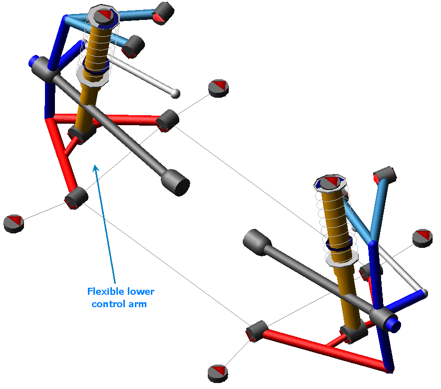
Figure 3 Flexible LCA Double-Wishbone Suspension
Template name
_double_wishbone_flex
Major role
Suspension
Application
Suspension and full-vehicle assemblies
Description
Flexible bodies replace the left and right rigid lower control arms.
MNF files referenced
LCA_left_tet.mnf and LCA_right_tet.mnf.
Topology
In addition to the general topology described for the Double-Wishbone Suspension, this template uses interface parts to connect the flexible bodies to the rest of the suspension. Node IDs define the location of interface parts.
Parameters, Communicators & Notes
Refer to the Double-Wishbone Suspension.
ISO Road Course
Overview
The ISO road course template represents a closed circuit with an ISO lane-change section.
Figure 4 ISO Road Course
Template name
_ISO_road_course
Major role
Environment
Application
With the optional Adams Driver module
Description
The ISO road course template consists of shell elements and frustums, and represents a closed circuit with an ISO lane-change section.
Files referenced
Geometry elements (shells) reference shell files stored in the Adams Car shared database in the shell_graphics.tbl directory. The shell files are Iso_road_inr.shl, Iso_road_otr.shl, and Iso_road_c.shl.
Topology
All the graphic elements are created on the ground part.
Parameters
Contains no parametric information.
Communicators
Contains no communicators.
Note: | The corresponding Adams Driver representation of this course is available as a trace on the x-y plane and lane width in the driver_roads.tbl directory. The file is called ISO_road_course.drd. You can use the file to run full-vehicle analyses with Adams Driver. Including the ISO road course template in your full-vehicle assembly adds a graphical representation of the circuit. |
Track System
Overview
The track template represents a closed-course racing circuit.
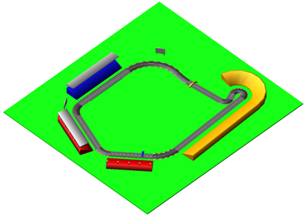
Figure 5 Track Template
Template name
_mdi_track
Major role
Environment
Application
Adams SmartDriver analysis.
Description
The track template consists of geometry elements representing a closed circuit.
Files referenced
The road geometry references a shell file stored in the Adams Car shared database in the shell_graphics.tbl directory. The shell file is mdi_track.shl.
Topology
All the graphic elements are created on the ground part.
Parameters
Contains no parametric information.
Communicators
Contains no communicators.
Note: | The corresponding Adams SmartDriver representation of this course is available as a trace on the x-y plane and lane width in the driver_roads.tbl directory. The file is called MDI_track.drd. You can use the file to run full-vehicle analyses with Adams SmartDriver. Including the track template in your full-vehicle assembly adds a graphical representation of the circuit. |
Leaf Spring
Overview
The leaf spring template consists only of the springs themselves, without any suspension members. The leaf spring design provides advantages in packaging, and it is generally used for light trucks and heavy-duty vehicles.
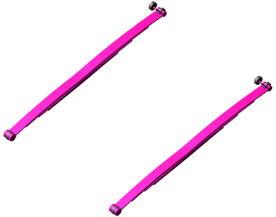
Figure 6 Leaf Spring
Template name
_example_leaf_spring
Major role
Leaf_spring
Application
Suspension and full-vehicle assemblies
Description
The leaf spring template represents the most common spring design for solid axle suspensions. You can use the template in conjunction with a front steerable suspension or with a rear non-steerable suspension.
Files referenced
Bushing property files and a leaf spring property file.
Topology
The leaf springs are modeled as a series of rigid bodies connected by beam elements. The leaf spring assembly may consist of several individual leaves of unique profiles and thicknesses, with contact and friction between leaves. Bushings connect the leaf springs and shackles to the body mount parts. The leaf spring seat is connected to the axle during assembly by an output communicator.
The following table lists the topological information of the leaf spring system.
The bushing: | Connects the part: | To the part: |
|---|---|---|
bg[lr]_leaf_to_shackle | leaf spring | shackle |
bg[lr]_leaf_to_frame | leaf spring | mtl_leaf_to_frame |
bg[lr]_shackle_to_frame | leaf spring | mtl_shackle_to_frame |
Communicators
Mount parts provide the connectivity from the template to the body subsystem. Output communicators publish the leaf spring seat part to the appropriate suspension subsystem. The following table lists the input and output communicators in the template.
The communicator: | Belongs to the class: | Has the role: |
|---|---|---|
ci[lr]_leaf_to_frame | mount | inherit |
ci[lr]_shackle_to_frame | mount | inherit |
co[lr]_leaf_to_axle | mount | inherit |
Leafspring Suspension
Overview
The leaf spring suspension template consists of the leaf springs documented above, in addition to a steerable solid axle suspension. The leaf spring design provides advantages in packaging, and it is generally used for light trucks and heavy-duty vehicles.
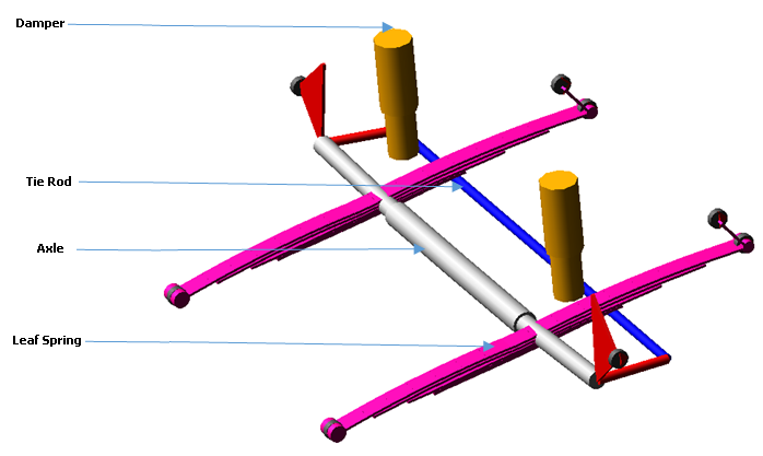
Figure 7 Leafspring Suspension
Template name
_example_susp_leaf
Major role
Suspension
Application
Suspension and full-vehicle assemblies
Description
The leaf spring suspension template represents the most common spring design for solid axle suspensions. This template includes steerable uprights, so you can use the template as a steerable front suspension. To model a non-steerable suspension, you may turn off the steering components by setting the parameter variable pvs_steerable_axle to 0.
Files referenced
Bushing, damper, and leaf spring property files.
Topology
The leaf springs are modeled as a series of rigid bodies connected by beam elements. The leaf spring assembly may consist of several individual leaves of unique profiles and thicknesses, with contact and friction between leaves. Bushings connect the leaf springs and shackles to the body mount parts. The leaf spring seat is connected to the axle through a bushing or fixed joint (the option is set in the leaf spring property file).
The following table lists the topological information of the leaf spring suspension system.
The joint: | Connects the part: | To the part: |
|---|---|---|
bg[lr]_hub_compliance | ge[lr]_spindle | ge[lr]_upright |
bg[lr]_leaf_to_frame | leaf spring | mt[lr]_leaf_to_frame |
bg[lr]_leaf_to_shackle | leaf spring | shackle |
bg[lr]_shackle_to_frame | leaf spring | mt[lr]_shackle_to_frame |
bg[lr]_shock_to_axle | ge[lr]_axle | ge[lr]_lower_shock_body |
bk[lr]_shock_to_frame | ge[lr]_upper_shock_body | mt[lr]_shock_to_frame |
jk[lr]hoo_top_mount_kinematic | ge[lr]_upper_shock_body | mt[lr]_shock_to_frame |
jo[lr]cyl_lower_upper_strut | ge[lr]_lower_shock_body | ge[lr]_upper_shock_body |
jo[lr]rev_axle_to_spindle | ge[lr]_spindle | ge[lr]_upright |
jo[lr]rev_upright_to_axle | ge[lr]_upright | ge[lr]_axle |
jo[lr]sph_hub_compliance | ge[lr]_spindle | ge[lr]_upright |
jo[lr]sph_tie_rod_to_upright | ges_tie_rod | ge[lr]_upright |
josfix_axle | gel_axle | ger_axle |
josper_tie_rod_ori | ges_tie_rod | gel_upright |
Parameters
Toe and camber variables in the template define the wheel spin axis, spindle part, and spindle geometry. The following table lists the parameters in the templates.
The parameter: | Takes the value: | Its units are: |
|---|---|---|
phs_kinematic_flag | integer | no units |
pv[lr]_camber_angle | real | degrees |
pv[lr]_toe_angle | real | degrees |
pvs_hub_compliance_active | integer | no units |
pvs_hub_compliance_offset | real | mm |
pvs_steerable_axle | integer | no units |
Communicators
Mount parts provide the connectivity from the template to the body subsystem. Output communicators publish the suspension upright part and toe, camber, steering input, and wheel-center location information to the appropriate subsystems and test rig.
The following table lists the input and output communicators in the template.
The communicator: | Belongs to the class: | Has the role: |
|---|---|---|
ci[lr]_leaf_to_frame | mount | inherit |
ci[lr]_shackle_to_frame | mount | inherit |
ci[lr]_shock_to_frame | mount | inherit |
co[lr]_camber_angle | parameter_real | inherit |
co[lr]_ride_height_ref | marker | inherit |
co[lr]_leaf_to_axle | mount | inherit |
co[lr]_suspension_mount | mount | inherit |
co[lr]_suspension_upright | mount | front |
co[lr]_toe_angle | parameter_real | front |
co[lr]_wheel_center | location | inherit |
cos_strarm_to_spindle | mount | front |
cos_suspension_parameters_ARRAY | array | inherit |
Note: | The integer parameter variables allow you to activate and deactivate the Hub Compliance. The kinematic flag variable toggles between kinematic and compliant mode. |
Loading System
Overview
The loading system template provides an example model of loading objects for a passenger car.
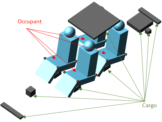
Figure 8 Loading System
Template name
_loading
Major role
loading
Application
full-vehicle assemblies
Description
The loading template consists of
Loading Objects
The loading object consists of a general part, a mount part, input communicator of type mount, and joint or bushing(s). The loading objects are divided into two categories:
■Cargo - general purpose loading object, such as luggage, with box graphics.
■Occupant - allows you to specify h-point location, and includes representative graphics of human occupants.
Loading Configuration
You can also create different sets of loading configurations using:
Files referenced
Bushing property files
Topology
All Cargo and Occupant loading parts connected to respective mount part through either fixed joint or bushing.
Parameters
Contains no parametric information.
Communicators
Mount parts provide the connectivity from the loading object to parts in other templates. This template does not contain any output communicators.
The following table lists the communicators in the template.
The communicator: | Entity class: | From minor role: | Matching names: |
|---|---|---|---|
cis_loa_dressed_power_plant | mount | inherit | loa_dressed_power_plant, body |
cis_loa_driver | mount | inherit | loa_driver, body |
cis_loa_front_bumper_attachment | mount | inherit | loa_front_bumper_attachment, body |
cis_loa_front_passenger | mount | inherit | loa_front_passenger, body |
cis_loa_fuel_tank_full | mount | inherit | loa_fuel_tank_full, body |
cis_loa_fuel_tank_half | mount | inherit | loa_fuel_tank_half, body |
cis_loa_luggage_driver | mount | inherit | loa_luggage_driver, body |
cis_loa_luggage_front_passenger | mount | inherit | loa_luggage_front_passenger, body |
cis_loa_luggage_rear_passenger_left | mount | inherit | loa_luggage_rear_passenger_left, body |
cis_loa_luggage_rear_passenger_right | mount | inherit | loa_luggage_rear_passenger_right, body |
cis_loa_panoramic_roof | mount | inherit | loa_panoramic_roof, body |
cis_loa_rear_bumper_attachment | mount | inherit | loa_rear_bumper_attachment, body |
cis_loa_rear_passenger_left | mount | inherit | loa_rear_passenger_left, body |
cis_loa_rear_passenger_right | mount | inherit | loa_rear_passenger_right, body |
cis_loa_spare_wheel | mount | inherit | loa_spare_wheel, body |
MacPherson Suspension
Overview
The MacPherson suspension design in this template is similar to the SLA geometry, and is probably the most often used suspension for passenger cars in the world. It uses a telescopic strut incorporating a damper element. The upper end is fixed to the body and the lower end is located by linkages. The MacPherson design provides advantages in packaging, and it is generally used for front-wheel-drive cars.
Figure 9 MacPherson Suspension
Template name
_macpherson
Major role
Suspension
Application
Suspension and full-vehicle assemblies
Description
The MacPherson suspension template represents the most common design for MacPherson suspensions. You can use the template as a front steerable suspension or as a rear non-steerable suspension.
You can set the subsystems based on this template to kinematic or compliant mode. In kinematic mode, Adams Car replaces the bushings with the corresponding kinematic constraints. The bushings connect the control arm and the damper strut to the body mount parts. You can also activate or deactivate driveshafts.
A spring acts between the upper strut part and the lower strut. Bumpstops and reboundstops are also present.
Files referenced
Bushings, springs, dampers, bumpstops, and reboundstops property files
Topology
The MacPherson suspension template represents a standard design employing a one-piece lower control arm (also known as A-arm) and a subframe. The upright to which the wheel mounts is located by the lower control arm, the tie rod, and the strut. The lower control arm regulates the fore-aft and lateral motions of the upright. The tie rod controls steering rotation of the upright, and the strut controls the vertical motion of the upright and the side and front view rotations, as well. A static rotation control actuator locks the rotational degree of freedom of the hub during quasi-static analyses.
The following table lists the topological information of the left side of the MacPherson suspension.
The joint: | Connects the part: | To the part: |
|---|---|---|
jklrev_lca | gel_lower_control_arm | ges_subframe |
jolsph_lca_balljoint | gel_upright | gel_lower_control_arm |
jolcyl_strut | gel_upright | gel_upper_strut |
jolsph_tierod_outer | gel_tierod | gel_upright |
jolcon_tierod_inner | gel_tierod | mtl_tierod_to_steering |
jksfix_subframe_rigid | ges_subframe | mts_subframe_to_body |
jklhoo_top_mount_kinematic | gel_upper_strut | mtl_strut_to_body |
joltra_tripot_to_differential | gel_tripot | mtl_tripot_to_differential |
jolcon_drive_sft_int_jt | gel_tripot | gel_drive_shaft |
jolcon_drive_sft_otr | gel_drive_shaft | gel_spindle |
Hub Compliance on | ||
jolsph_hub_compliance | gel_spindle | gel_upright |
Hub Compliance off | ||
jolrev_spindle_upright | gel_spindle | gel_upright |
Parameters
Toe and camber variables in the template define the wheel spin axis, spindle part, and spindle geometry. The following table lists the parameters in the templates.
The parameter: | Takes the value: | Its units are: |
|---|---|---|
phs_driveline_active | Integer | No units |
phs_kinematic_flag | Integer | No units |
pvs_hub_compliance_active | Integer | No units |
pv[lr]_toe_angle | Real | Degrees |
pv[lr]_camber_angle | Real | Degrees |
pv[lr]_drive_shaft_offset | Real | mm |
pvs_hub_compliance_offset | Real | mm |
Communicators
Mount parts provide the connectivity from the template to the body subsystems and differential. Output communicators publish toe, camber, steer axis, and wheel-center location information to the appropriate subsystems and test rig. The following table lists the input and output communicators in the template.
The communicator: | Belongs to the class: | Has the role: |
|---|---|---|
ci[lr]_ARB_pickup | location | inherit |
ci[lr]_strut_to_body | mount | inherit |
ci[lr]_tierod_to_steering | mount | inherit |
ci[lr]_tripot_to_differential | mount | inherit |
cis_subframe_to_body | mount | inherit |
co[lr]_arb_bushing_mount | mount | inherit |
co[lr]_camber_angle | parameter_real | inherit |
co[lr]_droplink_to_ suspension | mount | inherit |
co[lr]_ride_height_ref | marker | inherit |
co[lr]_suspension_mount | mount | inherit |
co[lr]_suspension_upright | mount | inherit |
co[lr]_toe_angle | parameter_real | inherit |
co[lr]_tripot_to_differential | location | inherit |
co[lr]_wheel_center | location | inherit |
cos_driveline_active | parameter_integer | inherit |
cos_rack_housing_to_ suspension_subframe | mount | inherit |
cos_suspension_parameters_ARRAY | array | inherit |
Note: | The integer parameter variables let you activate and deactivate the driveshafts and the Hub Compliance. The kinematic flag variable toggles between kinematic and compliant mode replacing the joints with the corresponding elastic elements. For example, Adams Car replaces the revolute joints that connect the lower control arms to the subframe with bushings |
Multi-Link Suspension
Overview
The multi-link suspension represents an independent suspension model for use as a rear suspension.
Figure 10 Multi-Link Suspension
Template name
_multi_link
Major role
Suspension
Application
Suspension and full-vehicle assemblies
Description
The multi-link suspension template represents a common rear independent suspension design. It includes a subframe (represented by the outline graphics) that is connected to the upper arm, to the lateral links, and to the track rod. The suspension is nonsteerable and intended to be used as a rear suspension only.
Files referenced
Springs, dampers, and bushings property files
Topology
Spherical joints, which are active in kinematic mode, connect the uprights to links. Bushings connect the trailing links to the mount parts. Springs and dampers act between the trailing links and the body. A static rotation control actuator locks the rotational degree of freedom of the hub during quasi-static analyses.
The following table provides a topological map of the template.
The joint: | Connects the part: | To the part: |
|---|---|---|
jklsph_hub_tl | gel_Upright | gel_Trailing_Link |
jklhoo_trailing_link_body | gel_Trailing_Link | mtl_trailing_link_body |
jklrev_ula_sbf | gel_upper | ges_Subframe |
joltra_dpr_upr_dpr_lwr | gel_Damper_Upper | gel_Damper_Lower |
jklsph_dpr_lwr_tl | gel_Damper_Lower | gel_Trailing_Link |
jklhoo_dpr_spring_seat_upper | gel_Damper_Upper | mtl_Spring_Seat_Upper |
jksfix_sbf_body | ges_Subframe | mtl_body_sbf_front |
jklsph_hub_ll | gel_Upright | gel_lateral |
jklsph_hub_tr | gel_Upright | gel_Track_Rod |
jklhoo_sbf_ll | ges_Subframe | gel_lateral |
jklhoo_sbf_tr | ges_Subframe | gel_Track_Rod |
jklsph_hub_ula | gel_Upright | gel_upper |
joltra_tripot_to_differential | gel_tripot | mtl_tripot_to_differential |
jolcon_drive_sft_int_jt | gel_tripot | gel_drive_shaft |
jolcon_drive_sft_otr | gel_drive_shaft | gel_spindle |
Hub Compliance on | ||
jolsph_hub_compliance | gel_spindle | gel_upright |
Hub Compliance off | ||
jolrev_spindle_upright | gel_spindle | gel_upright |
Parameters
Toe and camber variables in the template define the wheel spin axis, spindle part, and spindle geometry. The following table lists the parameters in the templates.
The parameter: | Takes the value: | Its units are: |
|---|---|---|
phs_driveline_active | Integer | No units |
phs_kinematic_flag | Integer | No units |
pvs_hub_compliance_active | Integer | No units |
pvs_subframe_active | Integer | No units |
pv[lr]_toe_angle | Real | Degrees |
pv[lr]_camber_angle | Real | mm |
pv[lr]_drive_shaft_offset | Real | mm |
pvs_hub_compliance_offset | Real | mm |
Communicators
The following table lists the communicators in the template.
The communicator: | Belongs to the class: | Has the role: |
|---|---|---|
ci[lr]_body_sbf_front | mount | inherit |
ci[lr]_body_sbf_rear | mount | inherit |
ci[lr]_Spring_Seat_Upper | mount | inherit |
ci[lr]_trailing_link_body | mount | inherit |
ci[lr]_tripot_to_differential | mount | inherit |
co[lr]_camber_angle | parameter_real | inherit |
co[lr]_ride_height_ref | marker | inherit |
co[lr]_suspension_mount | mount | inherit |
co[lr]_suspension_upright | mount | inherit |
co[lr]_tripot_to_differential | location | inherit |
co[lr]_wheel_center | location | inherit |
cos_driveline_active | parameter_integer | inherit |
cos_suspension_ parameters_ARRAY | array | inherit |
Note: | The integer parameter variables let you activate and deactivate the subframe part, the driveshafts and the Hub Compliance. The kinematic flag variable toggles between kinematic and compliant mode. |
Parallel-Link Steering System
Overview
The parallel-link steering system template is essentially a four-bar mechanism consisting of a pitman arm, center link, and idler arm.
Figure 11 Parallel-Link Steering
Template name
_parallel_link_steering
Major role
Steering
Application
Suspension and full-vehicle assemblies
Description
A recirculating ball steering gear transmits motion from the steering wheel to the pitman arm. The pitman arm rotates to impart motion to the center link and idler arm. The translation of the center link pulls and pushes the tie rods to steer the wheels.
Files referenced
Steering assist and torsion bar deflection property file. The default property file is mdi_steer_assis.ste, stored in the steer_assist.tbl directory of the shared Adams Car database.
Topology
The recirculating ball steering gear consists of three major parts:
■Ball screw
■Rack
■Sector
The steering wheel rotates the steering input shaft. A torsion bar attaches the steering input shaft to a ball screw. The ball screw imparts translational motion to the steering gear through a coupler. The steering gear, in turns, rotates the sector through a coupler, which is connected directly to the pitman arm shaft.
The following table maps the topology of the template.
The joint: | Connects the part: | To the part: |
|---|---|---|
joshoo_column_intermediate | ges_steering_column | ges_intermediate_shaft |
joshoo_intermediate_shaftinput | ges_intermediate_shaft | ges_input_shaft |
josrev_steering_wheel | ges_steering_wheel | ges_column_housing |
joscyl_steering_column | ges_steering_column | ges_column_housing |
josfix_column_housing_to_housing_mount | ges_column_housing | mts_steering_column_to_body |
jolsph_centerlink_arm | ges_center_link | gel_arm |
jolrev_pitman_arm_steering_gear | gel_arm | swl_steering_gear_mount |
josrev_ball_screw_steering_gear | ges_ball_screw | swl_steering_gear_mount |
josrev_input_shaft_steering_gear | ges_input_shaft | swl_steering_gear_mount |
jostra_rack_steering_gear | ges_rack | swl_steering_gear_mount |
josfix_steering_gear_housing | ges_steering_gear_housing | swl_steering_gear_mount |
josper_centerlink_pitman_arm | ges_center_link | gel_arm |
vfo_steering_assist | ges_rack | swl_steering_gear_mount |
gksred_ball_screw_input_shaft_lock | josrev_ball_screw_steering_gear | josrev_input_shaft_steering_ gear |
grsred_steering_wheel_column_lock | josrev_steering_wheel | joscyl_steering_column |
grsred_ball_screw_rack | josrev_ball_screw_steering_gear | jostra_rack_steering_gear |
grsred_pitman_arm_rack | jolrev_pitman_arm_steering_gear | jostra_rack_steering_gear |
Parameters
A parameter variable switches between kinematic and compliant mode, effectively defining the status of the ball screw input shaft lock reduction gear.
Communicators
The following table lists the communicators in the template.
The communicator: | Belongs to the class: | Has the role: |
|---|---|---|
ci[lr]_steering_gear_to_body | mount | inherit |
ci[lr]_steering_gear_to_suspension_subframe | mount | inherit |
cis_steering_column_to_ body | mount | inherit |
co[lr]_tierod_to_steering | mount | front |
cos_max_rack_ displacement | parameter_real | inherit |
cos_max_rack_force | parameter_real | inherit |
cos_max_steering_angle | parameter_real | inherit |
cos_max_steering_torque | parameter_real | inherit |
cos_steering_rack_joint | joint_for_motion | inherit |
cos_steering_wheel_joint | joint_for_motion | inherit |
Note: | The parallel-link steering template contains general spline elements. The general spline element gss_torsion_bar spline provides torque as a function of the angular deflection of the input shaft relative to the ball screw. A switch part is also present. It allows you to explore two different topological solutions. You can rigidly connect the steering gear to the body or to the suspension_subframe part. |
Pitman Arm Steering System
Overview
The pitman arm steering system template is a simple steering system derived from a parallel-link design. It is commonly used in trucks. It consists of a three-bar mechanism: pitman arm, draglink, and tie rod.
Figure 12 Pitman Arm Steering System
Template name
_pitman_arm
Major role
Steering
Application
Suspension and full-vehicle assemblies
Description
A recirculating ball steering gear transmits motion from the steering wheel to the pitman arm. The pitman arm rotates to impart motion to the draglink. The draglink pulls and pushes the tie rod and steers the wheels.
Files referenced
The point torque actuator references the torsion_bar datablock in the mdi_steering.ste property file, stored in the Adams Car shared database, under the steer_assists.tbl table or directory.
Topology
The recirculating ball steering gear consists of three major parts:
■Ball screw
■Rack
■Sector
The steering wheel rotates the steering input shaft. The steering input shaft attaches to the ball screw through a torsion bar, currently locked by a coupler. The ball screw imparts translational motion to the rack, through a coupler. The rack, in turns, rotates the sector through a coupler.
The sector is connected directly to the pitman arm shaft. The pitman arm drags the draglink, which is directly connected to the right wheel, and pulls the tie rod, connected to the left wheel. Spherical joints connect the draglink and tie rod.
The following table maps the topology of the template.
The joint: | Connects the part: | To the part: |
|---|---|---|
joshoo_column_intermediate | ges_steering_column | ges_intermediate_shaft |
joshoo_intermediate_shaft_input | ges_intermediate_shaft | ges_input_shaft |
josrev_steering_wheel | ges_steering_wheel | ges_column_housing |
joscyl_steering_column | ges_steering_column | ges_column_housing |
josfix_column_housing_to_housing_mount | ges_column_housing | mts_steering_column_to_body |
josrev_pitman_arm_steering_gear | mts_steering_gear_to_suspension_subframe | ges_idle_arm |
jossph_centerlink_arm | ges_idle_arm | ges_draglink |
josrev_input_shaft_steering_gear | ges_input_shaft | mts_steering_gear_to_suspension_subframe |
josrev_ball_screw_steering_gear | ges_ball_screw | mts_steering_gear_to_suspension_subframe |
jostra_rack_steering_gear | ges_rack | mts_steering_gear_to_suspension_subframe |
jossph_draglink_to_tierod | ges_draglink | ges_tierod |
grsred_steering_wheel_column_lock | josrev_steering_wheel | joscyl_steering_column |
gksred_ball_screw_input_shaft_lock | josrev_ball_screw_steering_gear | josrev_input_shaft_steering_gear |
grsred_pitman_arm_rack | josrev_pitman_arm_steering_gear | jostra_rack_steering_gear |
grsred_ball_screw_rack | josrev_ball_screw_steering_gear | jostra_rack_steering_gear |
Parameters
A parameter variable switches between kinematic and compliant mode, effectively defining the status of the ball screw input shaft lock reduction gear.
Communicators
The following table lists the Communicators in the template.
The communicator: | Belongs to the class: | Has the role: |
|---|---|---|
ci[lr]_steering_gear_to_suspension_subframe | mount | inherit |
cis_steering_column_to_ body | mount | inherit |
cos_tierod_to_steering | mount | front |
cos_draglink_to_steering | joint_for_motion | inherit |
cos_steering_wheel_joint | joint_for_motion | inherit |
Note: | The pitman arm steering system template does not interface with any of the Adams Car shared database suspension templates because those suspension templates have tie rods. To correctly assemble the pitman arm steering to a suspension subsystem, you must remove the tie rods from the suspension. The draglink and the tie rod have to be mounted to the left and right upright parts. |
Powertrain System
Overview
The Adams Car shared database includes a powertrain template, powertrain.tpl. The template models an engine, transmission, and a limited-slip differential that may be used for a front engine, front-wheel-drive vehicle, or a rear engine, rear-wheel-drive vehicle. Supplementary the differential can be used as central differential in a 4-wheel-drive vehicle, providing the torque at the differential outputs of the powertrain template as input to the front and rear differentials in the all wheel drive model.
Currently the template provides 4 different powertrain models which the user can switch between after the assembly is loaded using the menu “Simulate, Full-Vehicle Analysis, Vehicle Set-Up, Set Powertrain Parameters”. Alternatively the powertrain type can be switched through the design variable phs_powertrain_type:
■Manual: default powertrain type with engine, clutch, manual transmission, differential
■Simple: simplified engine model, no transmission model, differential
■Automatic: engine, torque converter, automatic transmission, differential
■Robotized: simplified engine model, simplified robotized clutch, transmission, differential
Figure 13 Powertrain
Template name
_powertrain
Major role
Powertrain
Application
Full-vehicle assemblies
Description – Manual
In this configuration, the powertrain system template represents an engine, clutch, manual transmission, and differential:
■Engine model - Consists of a single part (ges_engine) representing the total mass and inertia of the engine block, clutch housing, and transmission. A general spline element (gss_engine_torque) represents the engine's steady-state torque versus engine speed and throttle position. Before any analysis, gss_engine_torque is updated by reading the engine torque versus engine speed and throttle from a powertrain property file. For example, mdids://acar_shared/powertrains.tbl/V8_240HP_400Nm.pwr. See Torque versus Engine Speed and Throttle Position for this property file.
To allow for larger integration time steps during simulation, the engine crankshaft is not included as a part in the templates. Instead of a rotating crankshaft part, a differential equation (engine_omega) integrates the engine crankshaft's rotational acceleration (Adams Solver requires one integration time step for each 60 degrees of part rotation). The engine crankshaft's rotational acceleration is the difference between the engine torque and the clutch torque divided by the engine rotational inertia.
■Clutch model - The clutch torque is modulated by the clutch demand, which ranges in value from zero (0) to one (1):
■A clutch demand of zero means that the driver's foot is off the clutch pedal and the clutch is closed.
■A clutch demand of one means that the driver has pushed the clutch pedal completely to the floor and the clutch is open.
You can set the values of clutch demand, for which the clutch is completely closed or open, using the parameter variables pvs_clutch_closed and pvs_clutch_open.
The clutch develops torque only when it is at least partially closed and there is some slip displacement or slip speed between the engine crankshaft and the transmission input shaft. When the clutch is closed, it acts like a torsional spring-damper, except that the maximum clutch torque developed is limited by the clutch capacity, which you can modify (pvs_clutch_capacity).
You also set the clutch's torsional stiffness and damping. When the clutch is partially closed, the clutch stiffness and damping, as well as the clutch capacity (torque), are scaled by the clutch demand.
The clutch slip speed is the difference between the engine crankshaft and the transmission input shaft rotational speeds. When the clutch is closed, the clutch slip displacement is the integral of the clutch slip speed. When the clutch is open, the clutch slip displacement decays to zero with a time constant given by pvs_clutch_tau.
■Transmission model - The transmission model is simple: it applies the gear ratio selected by the gear demand, and has no rotating inertia. The clutch torque is multiplied by the selected gear ratio and applied to the differential input shaft. The differential input shaft speed is likewise multiplied by the same ratio to determine the transmission input shaft speed. You can set the number of gears and the ratio for each gear:
■A gear number of zero (0) represents neutral.
■A gear number of minus one (-1) represents reverse.
■Differential model - The differential model has rotating left and right output shaft parts that connect to half-shafts in suspension subsystems. The differential input shaft speed is the average of the left and right output shaft speeds multiplied by the final drive ratio you enter. Likewise, the transmission output torque is multiplied by the final drive ratio and then split equally between the two output shafts. A reaction torque is applied about the longitudinal axis to the ges_engine part.
The differential model includes a limited slip torque that acts between the left and right differential output shafts. The torque depends on the difference between the output shaft speeds. The limited slip torque-speed characteristic is read from a property file in the differentials.tbl.
Description – Simple
In this configuration, the powertrain system template has a simple engine model and differential:
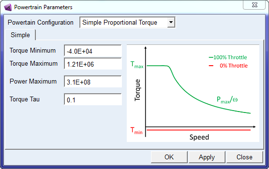
■Engine model - The engine model is mathematically defined as first order lag delay with specified time constant applied over a simplified torque/speed characteristic. The torque provided is proportional to the throttle command between Tmin and Tmax according to the following plot:
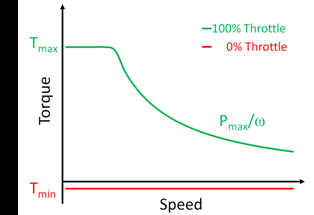
The user needs to provide the value of Tmax, Tmin and Pmax. This model approximates the ideal case of a CVT powertrain with continuous variable transmission ratio. A transmission model is not necessary in this powertrain configuration. The engine speed is the same as the differential input speed.
■Differential model - The differential model is the same model as the Manual powertrain.
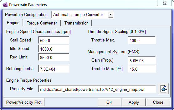
Description – Automatic
In this configuration, the powertrain system template represents an engine, torque converter, automatic transmission, and differential:
■Engine model - The engine model is the same model as the Manual powertrain.
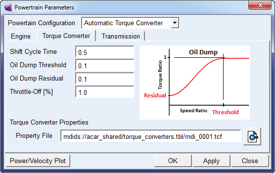
■Torque converter - Note that the torque converter property file uses the same conventions for the capacity factor and torque ratio curves that are used for Adams Driveline. It is possible to use the same torque converter property file with the simplified model and with Driveline (refer example property file). The simplified model uses only the capacity factor and torque ratio curves from the property file, other data is not used.
The simplified model does mimic a "lock-up" condition only during "straight" or "skidpad" equilibrium solutions for stability reasons (and an ensuing dynamic solution will show a transient response as the torque converter begins to slip) and does not use any of the lock-up clutch data from the property file.
■Transmission model - The transmission model is similar to the Manual case with no rotating inertia. A built-in controller is provided to select the proper gear depending on the input speed and the shift points table specified in the interface. The model shifts from the old to the new gear ratio when the input speed reaches the corresponding shift point. The transition is obtained using a step function over the specified shift cycle time. The torque output from the transmission therefore is continuous and simulates the engagement/disengagement of clutches in a real automatic gearbox.
The controller has intelligent shift logic depending on the throttle position from the driver. The actual up shift point is interpolated between “Shift-Up” and “Shift-Up Sport” thresholds. Therefore the actual shift points constantly vary depending on the driver demand, allowing for an economy mode at lower throttle and sport mode at higher one.
■Differential model - The differential model is the same model as the Manual powertrain.
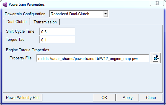
Description – Robotized
In this configuration, the powertrain system template represents an engine, simplified robotized clutch, automatic transmission, and differential:
■Engine model - The engine model is a simplified version of the Manual powertrain. It uses a general spline element (gss_engine_torque) to represent the engine's steady-state torque versus engine speed and throttle position, but does not have rotating inertia for torque response. A first order lag delay is applied over the nominal value of torque in the same fashion as Simple powertrain, however Robotized model allows for a more detailed torque definition through the gss_engine_torque spline.
■Robotized clutch - Step functions are used to transition between gear ratios. This models works in conjunction with the same intelligent controller of Automatic, providing the modulation of torque and the engine speed control. The user can specify the cycle shift time in the interface. This model provides a smoother shift than the manual transmission where the driver interrupts the torque transmitted by completely disengaging the clutch. The controller works in Automatic mode, while Manumatic mode will be supported in further releases.
■Transmission model - The transmission model is the same as the Manual powertrain.
■Differential model - The differential model is the same model as the Manual powertrain.
Files referenced
The file, V12_engine_map.pwr, stored in the powertrains.tbl directory, defines the engine map. The differential references the MDI_viscous.dif property file, stored in the differentials.tbl directory. The torque converter properties reference the mdi_0001.tcf property file, stored in the torque_converters.tbl directory. The MDI_viscous.dif property file defines the slip torque-speed relationship as a two-dimensional spline.
Topology
The powertrain template contains very simple topological information because it is a functional representation of the powertrain. The only general rigid parts, besides the engine body, are the diff outputs and the revolute joints that connect the rigid bodies to the engine body.
Parameters
The following table lists the powertrain system template parameters.
The parameter: | Takes the value: | Its units are: | Description: |
|---|---|---|---|
phs_powertrain_type | Integer | No units | Value =1, Manual Value =2, Simple Value =3, Automatic Value = 4, Robotized |
phs_kinematic_flag | Integer | No units | When flag = 1, engine is rigidly mounted to chassis; when flag = 0, engine is mounted on bushings. Set from the Adjust menu. |
pvs_clutch_capacity | Real | Torque | Maximum torque clutch can sustain with zero slip speed. |
pvs_clutch_close | Real | No units | Value of clutch demand at which clutch is fully closed. Value should be less than pvs_clutch_open and in the range of 0 and 1. |
pvs_clutch_damping | Real | Torsional_damping | Clutch damping torque per unit of clutch slip speed. |
pvs_clutch_open | Real | No units | Value of clutch demand at which clutch is open. |
pvs_clutch_stiffness | Real | Torsional_stiffness | Clutch torque developed per unit of clutch slip. |
pvs_clutch_tau | Real | Time | Time constant for clutch slip decay when clutch is open. |
pvs_ems_gain | Real | No units | Proportional gain used in EMS idle speed control |
pvs_ems_max_throttle | Real | No units | Value of throttle demand that corresponds to the maximum capability of the EMS system |
pvs_engine_idle_speed | Real | RPM | Engine idle speed in RPM. |
pvs_engine_inertia | Real | Inertia | Engine rotational inertia. Must be greater than zero. |
pvs_engine_rev_limit | Real | RPM | Maximum engine speed in RPM. |
pvs_engine_stall_speed | Real | RPM | Engine stall speed in RPM |
pvs_final_drive | Real | No units | Differential input shaft (pinion) to ring gear ratio. |
pvs_gear_downshift_[2-6] | Real | RPM | Shift point values for downshifting in gear 1-5. |
pvs_gear_sport_[1-5] | Real | RPM | Shift point values for upshifting in gear 2-6 when throttle is higher than Shift-Up Sport threshold. |
pvs_gear_ratio_[1-6,R] | Real | No units | Transmission input shaft to output shaft ratio for gears 1 through 6 and reverse. |
pvs_gear_upshift_[1-5] | Real | RPM | Shift point values for upshifting in gear 2-6 when throttle is lower than Shift-Up threshold. |
pvs_gear_upshift_thlds | Real | No units | Throttle values to define economy Shift-Up and sport Shift-Up Sport shifting limits. |
pvs_graphics_flag | Integer | No units | 1 = include powertrain graphics; 0 = do not include powertrain graphics |
pvs_sportsmode_flag | Integer | No units | 1 = use sports mode upshift speeds; 0 = use standard upshift speeds |
pvs_max_engine_power | Real | Power | Max engine power for simplified engine model corresponding to 100% throttle. |
pvs_max_engine_torque | Real | Torque | Max engine torque (cap at lower speed) for simplified engine model corresponding to 100% throttle. |
pvs_max_gears | Integer | No units | Number of gear ratios in the transmission. |
pvs_max_throttle | Real | No units | Value of throttle demand for which throttle is fully open (throttle demand = 0 is throttle closed). |
pvs_min_engine_torque | Real | Torque | Min engine torque for simplified engine model corresponding to 0% throttle. |
pvs_oil_dump_residual | Real | No units | Fraction of torque produced at a speed ratio of zero ('oil dumped'). |
pvs_oil_dump_threshold | Real | No units | Speed ratio at which torque attenuation ('oil dump') is initiated. |
pvs_oil_dump_throttle_off | Real | No units | Percentage of full throttle at which 'oil dump' is allowed. |
pvs_shift_cycle_time | Real | Time | Shifting cycle time for Automatic and Robotized transmissions. |
pvs_torque_tau | Real | Time | Time that the system's step response takes to reach 63.2% of its final value. Applied to Simple and Robotized engine model |
The above list of parameters has been collected in dialog boxes for a better selection depending on the powertrain type.
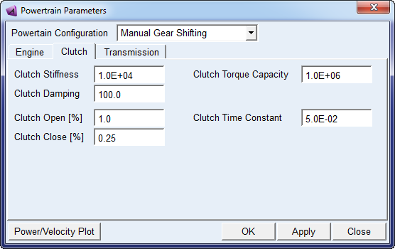
1. Manual Gear Shifting
♦Engine model parameters:
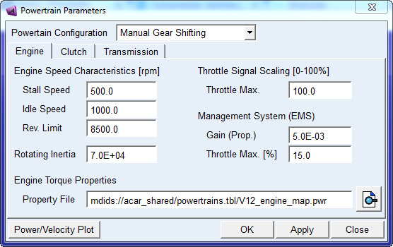
♦Clutch model parameters:
■Transmission model parameters:
2. Simple Proportional Torque
♦Simple:
3. Automatic Torque Converter
♦Engine model parameters:
♦Torque Converter model parameters:
♦Transmission model parameters:
4. Robotized Dual-Clutch
♦Dual-Clutch model parameters:
♦Transmission model parameters:
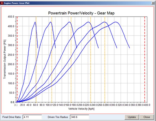
After setting up the transmission parameters in the Manual, Automatic and Robotized powertrain types, you can optimize the selection of shift points for given engine map, final drive, tire radius by reviewing the available transmission output power ("Power/Velocity Plot"):
Communicators
Mount parts provide the connectivity from the template to the body subsystems. Output communicators publish information, such as engine RPM and transmission spline. The following tables list the input and output communicators in the powertrain system template.
Input Communicators
The communicator: | Entity class: | From minor role: | Matching name: |
|---|---|---|---|
ci[lr]_diff_tripot | location | inherit | tripot_to_differential |
ci[lr]_tire_force | force | inherit | tire_force |
cis_clutch_demand | solver_variable | inherit | clutch_demand |
cis_engine_to_subframe | mount | inherit | engine_to_subframe |
cis_initial_engine_rpm | parameter_real | any | initial_engine_rpm |
cis_powertrain_to_body | mount | inherit | powertrain_to_body |
cis_sse_diff1 | diff | inherit | sse_diff1 |
cis_throttle_demand | solver_variable | inherit | throttle_demand |
cis_transmission_demand | solver_variable | inherit | transmission_demand |
Output Communicators
The communicator: | Entity class: | To minor role: | Matching name: |
|---|---|---|---|
co[lr]_output_torque | force | inherit | output_torque |
co[lr]_tripot_to_differential | mount | inherit | tripot_to_differential |
cos_clutch_displacement_ic | solver_variable | inherit | clutch_displacement_ic |
cos_diff_ratio | parameter_real | inherit | diff_ratio |
cos_engine_map | spline | inherit | engine_map |
cos_engine_revlimit_rpm | parameter_real | inherit | engine_revlimit_rpm |
cos_engine_rpm | solver_variable | inherit | engine_rpm |
cos_engine_speed | parameter_real | inherit | engine_speed |
cos_engine_stall_rpm | parameter_real | inherit | engine_stall_rpm |
cos_max_engine_driving_torque | solver_variable | inherit | engine_maximum_driving_torque |
cos_max_engine_braking_torque | solver_variable | inherit | engine_maximum_braking_torque |
cos_max_gears | parameter_integer | inherit | max_gears |
cos_max_throttle | parameter_real | inherit | max_throttle |
cos_powertrain_gse | gse | inherit | powertrain_gse |
cos_powertrain_type | parameter_integer | inherit | gse_powertrain_type |
cos_transmission_input_omega | solver_variable | inherit | transmission_input_omega |
cos_transmission_spline | spline | inherit | transmission_spline |
Note: | The solver_variable "analysis_type" indicates whether the analysis is steady-state or dynamic. When the analysis_type is steady-state the engine torque map and transmission gear ratios are ignored. |
Quad-Link Axle Suspension
Overview
The quad-link axle suspension template is an example of a dependent suspension model. The wheels are mounted at either end of a rigid beam so the movement of one wheel is transmitted to the opposite wheel causing them to steer and camber together. Solid beam axle suspensions are commonly used on the front of heavy trucks, where high-load carrying capacity is required.
Figure 14 Quad-Link Axle Suspension
Template name
_quad_link_axle
Major role
Suspension
Application
Suspension and full-vehicle assemblies
Description
The quad-link axle suspension template represents a common design for solid axles suspensions. You can use the template as a front steerable suspension or as rear nonsteerable suspension.
You can set subsystems based on this template to kinematic or compliant mode. In kinematic mode, Adams Car replaces the bushings that connect the lower and upper links to the body mount part with the corresponding purely kinematic constraints.
Files referenced
Bushing, spring, and damper property files
Topology
Spherical joints connect the upper and lower links to the solid axle. The draglink is attached to the bell crank. The bell crank moves the tie rod, which steers the wheels. Revolute joints connect the uprights to the solid axle. A joint force actuator locks the hub to the wheel carrier. The following table maps the topology of the template.
The joint: | Connects the part: | To the part: |
|---|---|---|
jklhoo_lower_link_frame | gel_lower_link | mtl_lower_link_frame |
jklhoo_upper_link_frame | gel_upper_link | mtl_lower_link_frame |
jklsph_upper_link_axle | gel_upper_link | ges_axle |
jklsph_lower_link_axle | gel_lower_link | ges_axle |
jolrev_knuckle_axle | gel_knuckle | ges_axle |
josrev_bell_crank_axle | ges_bell_crank | ges_axle |
jossph_draglink_pitman_arm | ges_draglink | mts_draglink_steering |
joshoo_draglink_bell_crank | ges_draglink | ges_bell_crank |
jossph_tierod_knuckle | ges_tierod | gel_knuckle |
josinp_tie_rod_bell_crank | ges_tierod | ges_bell_crank |
Hub Compliance on | ||
jolsph_hub_compliance | gel_hub | gel_knuckle |
Hub Compliance off | ||
jolrev_bearing | gel_hub | gel_knuckle |
Parameters
Toe and camber variables define wheel spin axis, spindle part, and spindle geometry. The following table lists the parameters in the template.
The parameter: | Takes the value: | Its units are: |
|---|---|---|
phs_kinematic_flag | Integer | No units |
pvs_hub_compliance_active | Integer | No units |
pv[lr]_toe_angle | Real | Degrees |
pv[lr]_camber_angle | Real | Degrees |
pvs_hub_compliance_offset | Real | mm |
Communicators
Mount parts provide the connectivity from the template to body subsystems and steering. Output communicators publish toe, camber, steer axis, and wheel center location information to the appropriate subsystems and the test rig. The following table lists the input and output communicators.
The communicator: | Belongs to the class: | Has the role: |
|---|---|---|
ci[lr]_lower_link_frame | mount | inherit |
ci[lr]_spring_upper_to_body | mount | inherit |
ci[lr]_upper_link_frame | mount | inherit |
cis_draglink_steering | mount | inherit |
co[lr]_camber_angle | parameter_real | inherit |
co[lr]_ride_height_ref | marker | inherit |
co[lr]_suspension_mount | mount | inherit |
co[lr]_suspension_upright | mount | inherit |
co[lr]_toe_angle | parameter_real | inherit |
co[lr]_wheel_center | location | inherit |
cos_suspension_ parameters_ARRAY | any | inherit |
Note: | The integer parameter variables let you activate and deactivate the Hub Compliance. The kinematic flag variable toggles between kinematic and compliant mode. |
Rack and Pinion Steering System
Overview
The rack and pinion steering system is usually found in passenger cars. The pinion gear translates the rotary motion of the steering wheel into the linear motion of the rack. The rack moves the tie rods back and forth to steer the vehicle.
Figure 15 Rack and Pinion Steering System
Template name
Template | Description |
|---|---|
_rack_pinion_steering | basic model |
_rack_pinion_steering_MachineryGear | AMachinery rack & pinion with simplified gear force |
_rack_pinion_steering_MachineryGear_3D | AMachinery rack & pinion with 3D gear force |
_rack_pinion_steering_MachineryMotor | AMachinery motor supplies additional assist torque |
Major role
Steering
Application
Suspension and full-vehicle assemblies
Description
A series of hooke joints, which connect the three steering column shafts, transmit motion from the steering wheel to the pinion. A revolute joint connects the lower column shaft to the rack housing. A bushing (torsion bar) connects the shaft to the pinion. A revolute joint connects the pinion to the rack housing.
In kinematic mode, a reduction gear is active and connects the steering input shaft revolute joint to the pinion revolute joint. The underlying Adams View entity (a coupler) is active only in kinematic mode. The reduction gear (pinion to rack) converts pinion rotational motion to the rack translational motion. A translational joint constrains the rack to the rack housing. An additional VFORCE provides the steering assist force.
Files referenced
Property files, hydraulic_steering_assist.ste or electric_steering_assist.ste or torsion_bar.ste and steering_compliance.ste are stored in the steer_assist.tbl of the acar_concept database. These defines the steering hydraulic assist force, electric steering assist, torsion bar and steering compliance respectively.
Topology
The following table maps the topology of the template.
The attachment: | Connects the part: | To the part: |
|---|---|---|
joshoo_column_intermediate | ges_steering_column | ges_intermediate_shaft |
joshoo_intermediate_shaftinput | ges_intermediate_shaft | ges_steering_shaft |
jostra_rack_to_rackhousing | ges_rack | ges_rack_housing |
josrev_steering_wheel | ges_steering_wheel | mts_steering_column_to_body |
josrev_pinion | ges_pinion | ges_rack_housing |
joscyl_steering_column_to_body | ges_steering_column | mts_steering_column_to_body |
josrev_steering_input_shaft | ges_steering_shaft | ges_rack_housing |
jksfix_rigid_rack_housing_mount | ges_rack_housing | sws_rack_house_mount |
The force: | Connects the part: | To the part: |
steering_assist_vforce | ges_rack | ges_rack_housing |
The reduction gear: | Constrains the joint: | To the joint: |
gksred_input_shaft_pinion_lock | josrev_steering_input_shaft | josrev_pinion |
grsred_steering_wheel_column_lock | josrev_steering_wheel | joscyl_steering_column_to_body |
The following reduction gear is replaced by Adams Machinery gear elements in the _rack_pinion_steering_MachineryGear templates: | ||
grsred_pinion_to_rack | josrev_pinion | jostra_rack_to_rackhousing |
Parameters
A parameter variable switches between kinematic and compliant mode. You can set the activity of the steering assist force through the hidden parameter variable, steering_assist_active. A series of parameters define the maximum values of angle, rack displacement, rack force, and steering-wheel torque.
Communicators
The following table lists the input and output communicators.
The communicator: | Belongs to the class: | Has the role: |
|---|---|---|
cis_rack_housing_to_ suspension_subframe | mount | inherit |
cis_rack_to_body | mount | inherit |
cis_steering_column_to_ body | mount | inherit |
co[lr]_tierod_to_steering | mount | front |
cos_max_rack_ displacement | parameter_real | inherit |
cos_max_rack_force | parameter_real | inherit |
cos_max_steering_angle | parameter_real | inherit |
cos_max_steering_torque | parameter_real | inherit |
cos_steering_rack_joint | joint_for_motion | inherit |
cos_steering_wheel_joint | joint_for_motion | inherit |
Note: | The rack and pinion steering system template contains a general spline element to define the assist pressure vs. torsion bar deflections. The template also contains a switch part, which lets you explore two different topological solutions: you can connect the steering rack housing to the body or to the suspension subframe. |
Front Driveline System
Overview
The front driveline system template provides an example model of a driveline for front-wheel drive (FWD) vehicles.
Figure 16 Front Driveline System
Template name
_driveline_fwd
Major role
Driveline
Application
Full-vehicle assemblies
Description
An actuator drives the front diff input, which acts through the differential to drive the diff outputs. Diff outputs should be connected to the front wheels.
Files referenced
None.
Topology
The front driveline template consists of a differential housing which mounts to the powertrain, and diff input/ouputs which mount to the housing via revolute joints. The differential is an open design rather than a limited slip. The following table maps the topology of the template.
The joint: | Connects the part: | To the part: |
|---|---|---|
josrev_diff_input_to_housing | ges_diff_input | mts_diff_housing_to_powertrain |
jolrev_diff_output_to_housing | gel_diff_output | mts_diff_housing_to_powertrain |
jorrev_diff_output_to_housing | ger_diff_output | mts_diff_housing_to_powertrain |
Parameters
The parameter variable drive_torque_bias_front is communicated to the driver testrig via output communicator cos_drive_torque_bias_front.
Limitations
The front driveline template uses a number of rotating parts. If the driveline dynamics are not of interest to you, then it is more efficient to apply direct drive torque to the wheels, because the rotating parts in the template might slow the numerical integration during the Analysis.
Communicators
Output communicators of the type mount publish the left and right differential outputs to the suspension templates and subsystems. The following table lists the input and output communicators.
The communicator: | Belongs to the class: | Has the role: |
|---|---|---|
ci[lr]_tripot_to_differential | location | front |
cis_diff_housing_to_powertrain | mount | inherit |
cis_driveline_torque | solver_variable | inherit |
Rear Driveline System
Overview
The rear driveline system template provides an example model of a driveline for rear-wheel drive (RWD) vehicles.
Figure 17 Rear Driveline System
Template name
_driveline_rwd
Major role
Driveline
Application
Full-vehicle assemblies
Description
The rotational motion of the front propshaft is transmitted to the rear shaft and from there to the diff outputs. Diff outputs should be connected to the driving wheels.
Files referenced
Bushing property files
Topology
The rear driveline template consists of a two-piece propshaft, a slip yoke, and a differential. For convenience, the template includes the propshaft input part for applying motion or torque. The propshaft input part attaches to the powertrain through a revolute joint. A bearing supports it at its aft.
The front propshaft attaches to the support bearing through an inline joint primitive that prevents translation of the front propshaft perpendicular to the propshaft's spin axis.
Hooke joints transmit the motion to the slip yoke part. The slip yoke supports and transmits torque to the rear propshaft through a translational joint. The differential input shaft receives torque from the rear propshaft through a hooke joint.
The differential is an open design rather than a limited slip. Four bushings mount it to the body. Setting kinematic mode fixes the differential housing to the body and deactivates the bushings. The following table maps the topology of the template.
The joint: | Connects the part: | To the part: |
|---|---|---|
josrev_diff_input | ges_diff_input | ges_diff_housing |
jolrev_diff_output | gel_diff_output | ges_diff_housing |
jorrev_diff_output | ger_diff_output | ges_diff_housing |
joshoo_propshaft_at_diff | ges_propshaft_rear | ges_diff_input |
joshoo_propshaft_input_to_ front | ges_propshaft_input | ges_propshaft_front |
joscon_propshaft_front_to_ yoke | ges_propshaft_front | ges_slip_yoke |
jostra_propshaft_rear_to_yoke | ges_propshaft_rear | ges_slip_yoke |
josrev_propshaft_input_to_ trans | ges_propshaft_input | mts_propshaft_input_to_powertrain |
jksfix_diff_housing_to_body | ges_diff_housing | mts_diff_housing_to_body |
josinl_support_bearing_to_propshaft_front | ges_support_bearing | ges_propshaft_front |
josori_support_bearing_orientation | ges_support_bearing | mts_propshaft_support_to_body |
josinp_support_bearing_ location | ges_support_bearing | mts_propshaft_support_to_body |
jksinl_support_bearing_to_ body | ges_support_bearing | mts_propshaft_support_to_body |
grsdif_differential | josrev_diff_input | jolrev_diff_output |
grsdif_differential | josrev_diff_input | jorrev_diff_output |
grsdif_differential | jolrev_diff_output | jorrev_diff_output |
Parameters
The parameter variable final_drive_ratio defines the pinion to ring ratio.
Limitations
The rear driveline template uses a number of rotating parts. If the driveline dynamics are not of interest to you, then it is more efficient to apply direct drive torque to the wheels, because the rotating parts in the template might slow the numerical integration during the Analysis.
Communicators
Output communicators of the type mount publish the left and right differential output shafts to the suspension templates and subsystems. The following table lists the input and output communicators.
The communicator: | Belongs to the class: | Has the role: |
|---|---|---|
ci[lr]_tripot_to_differential | location | rear |
cis_diff_housing_to_body | mount | inherit |
cis_driveline_torque | solver_variable | inherit |
cis_propshaft_input_to_ powertrain | mount | inherit |
cis_propshaft_support_to_ body | mount | inherit |
co[lr]_tripot_to_differential | mount | rear |
Rigid Chassis
Overview
The rigid chassis template represents the base frame of a vehicle.
Figure 18 Rigid Chassis
Template name
_rigid_chassis
Major role
body
Application
Suspensions, tires, and steering systems in full-vehicle assemblies
Description
A single rigid body part models the chassis, and a trim part mass is used to adjust the weight distribution.
Files referenced
Shell elements create the chassis graphic. All the shell files are stored in the Adams Car shared database, in the shell_graphics.tbl directory.
Topology
The ges_chassis part is unconstrained, and the ges_trim_mass part fixed to ges_chassis.
Parameters
The rigid chassis template defines a series of parameter variables, most of which are used to compute the aerodynamic forces acting on the body. The following table lists the parameters in the template. For a detailed description of the force function, see Force Function Description.
The parameter: | Takes the value: | Its units are: |
|---|---|---|
pvs_aero_drag_active | Integer | No units |
pvs_aero_frontal_area | Real | Area |
pvs_air_density | Real | Density |
pvs_drag_coefficient | Real | No units |
Force function description
Adams Car expects air density and area parameter variables to be in model units.
As a result of an air stream interacting with the vehicle, forces and moments are imposed on the vehicle. Out of the three forces and three moments, only the most relevant ones are modeled in the template. The aerodynamic general force takes into consideration the drag force (longitudinal force) and torque (pitching moment and torque along the y-axis of the vehicle, in the SAE coordinate system). In detail:
F = 0.5 x AirDensity x DragCoeff x Area x VX(chassis)2
T = F x DZ (RideHeight)
The pitching moment acts to transfer weight between the front and rear axles. It arises because the drag does not act at the ground plane. Therefore, it accounts for the elevation of the drag force.
Limitations
The rigid body modeling of the chassis does not account for torsional stiffnesses and other effects. You could create a more accurate representation of a chassis frame by connecting the multiple rigid bodies though spring dampers to take into account torsional stiffnesses and using modal flexibility.
Communicators
The rigid chassis template defines a series of mount part communicators. The assembly process matches them with the corresponding output communicators created in suspensions, steering, and other subsystems. The following table lists the communicators. Note that the output communicator tierod_to_steering (rear) allows the tierod_to_steering mount parts in the rear suspension to connect to the chassis body.
The communicator: | Belongs to the class: | Has the role: |
|---|---|---|
cis_std_tire_ref | location | inherit |
co[lr]_mbr_insul_fr | mount | inherit |
co[lr]_mbr_insul_rr | mount | inherit |
co[lr]_spring_to_body | mount | inherit |
co[lr]_strut_to_body | mount | inherit |
co[lr]_s_abs_upr_insul | mount | inherit |
co[lr]_tierod_to_steering | mount | rear |
co[lr]_trod | mount | inherit |
co[lr]_tv_link | mount | inherit |
co[lr]_uca_to_body | mount | any |
co[lr]_upr_link_fr | mount | inherit |
co[lr]_upr_link_rr | mount | inherit |
co[lr]_upr_s_abs | mount | inherit |
cos_aero_drag_force | force | inherit |
cos_aero_frontal_area | parameter_real | inherit |
cos_air_density | parameter_real | inherit |
cos_body | mount | inherit |
cos_body_subsystem | mount | inherit |
cos_chassis_path_ reference | mount | inherit |
cos_concept_to_body | mount | inherit |
cos_diff_housing_to_body | mount | rear |
cos_drag_coefficient | parameter_real | inherit |
cos_driver_reference | mount | inherit |
cos_measure_for_distance | mount | inherit |
cos_powertrain_to_body | mount | inherit |
cos_propshaft_support_to_body | mount | rear |
cos_rack_to_body | mount | inherit |
cos_steering_column_to_ body | mount | inherit |
cos_subframe_to_body | mount | inherit |
cos_trim_part | part | inherit |
Note: | The rigid chassis light template (_rigid_chassis_lt) is exactly the same as the rigid chassis template (_rigid_chassis), but without the shell graphic geometry. |
Simple Anti-Roll Bar System
Overview
The simple anti-roll bar system template represents a bar fitted transversely to the suspension. The bar is made out of steel or a user-defined material. The bar is installed in a vehicle to reduce the roll of the vehicle body as the vehicle takes a corner. It increases suspension roll rate.
Figure 19 Simple Anti-Roll Bar System
Template name
_antiroll_simple
Major role
Antiroll
Application
Suspension and full-vehicle analyses
Description
The anti-roll bar system template provides a simple model of anti-roll bar (also known as stabilizer bar). It consists of two bar halves connected by a torsional spring-damper component.
Files referenced
Bushing property files
Topology
A revolute joint connects the two bar halves of the anti-roll bar system. Bushings then attach the bar halves to the body or to the suspension subframe. Drop links transmit the suspension motion to the bar ends. The drop links attach to the suspension with spherical joints and to the bar ends with convel joints.
The following table maps the topology of the anti-roll bar system template.
The joint: | Connects part: | To part: |
|---|---|---|
jo[lr]sph_droplink_ upper_bal | ge[lr]_droplink | mt[lr]_droplink_to_suspension |
jo[lr]con_droplink_to_arb | ge[lr]_droplink | ge[lr]_arb |
josrev_arb_rev_joint | ger_arb | gel_arb |
arb_torsion_spring (rotational spring) | ger_arb | gel_arb |
Parameters
A parameter variable (pvs_torsional_stiffness) defines the torsional stiffness of the spring-damper component. The following table lists the parameter, its value, and units.
The parameter: | Takes the value: | Its units are: |
|---|---|---|
pvs_torsional_stiffness | Real variable | Nmm/Degrees |
Limitations
The anti-roll bar system template represents a simple approximation of a stabilizer bar. For more complex solutions, you would need to create a more accurate representation of the bar through the discretization of rigid bodies, nonlinear rods, or flexible bodies.
Communicators
Mount parts provide the connectivity to the suspension subsystems. An output communicator exports information about the location of the ARB pick-up point.
The following table lists the communicators that the template uses.
The communicator: | Belongs to the class: | Has the role: |
|---|---|---|
ci[lr]_arb_bushing_mount | mount | inherit |
ci[lr]_droplink_to_suspension | mount | inherit |
co[lr]_ARB_pickup | location | inherit |
Notes: | The spring-damper component applies a rotational action-reaction force between the two bar halves. The following linear equation describes the torque applied at the i marker: Ta = -C(da/dt) - Kt (a - ANGLE) + TORQUE where: ■C is the damping term (defaults to 0 in the template). ■Kt is the torsional stiffness. ■a is the angle between the bar halves. ■ANGLE is the initial angular displacement. ■TORQUE is the torsional preload. Torque applied on the j marker is equal and opposite to the torque on the i marker. |
FE Part Anti-Roll Bar System
Overview
The FE Part anti-roll bar system template represents a bar fitted transversely to the suspension. The bar is made out of steel or a user-defined material. The bar is installed in a vehicle to reduce the roll of the vehicle body as the vehicle takes a corner. It increases suspension roll rate.
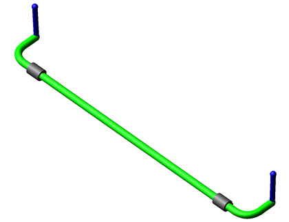
Figure 20 FE Part Anti-Roll Bar System
Template name
_antirollbar_FE_part
Major role
Antiroll
Application
Suspension and full-vehicle analyses
Description
This anti-roll bar system template provides a more advanced model of anti-roll bar (also known as stabilizer bar). It consists of a single FE Part representing the bar itself, and rigid links that connect to the suspension. The stiffness of the bar is calculated automatically based on the profile and the cross-section. The profile of the bar can be modified by moving the hardpoints. The cross-section can be modified by editing the existing section object (arb_solid) or creating a new one.
Files referenced
Bushing property files
Topology
Bushings attach the bar to the body or to the axle housing. Drop links transmit the suspension motion to the bar ends. The drop links attach to the suspension with spherical joints and to the bar ends with convel joints.
The following table maps the topology of the anti-roll bar system template.
The joint: | Connects part: | To part: |
|---|---|---|
jo[lr]sph_droplink_ upper_ball | ge[lr]_droplink | mt[lr]_droplink_to_suspension |
jo[lr]con_droplink_to_bar | ge[lr]_droplink | fes_arb |
Communicators
Mount parts provide the connectivity to the suspension subsystems. An output communicator exports information about the location of the ARB pick-up point.
The following table lists the communicators that the template uses.
The communicator: | Belongs to the class: | Has the role: |
|---|---|---|
ci[lr]_arb_bushing_mount | mount | inherit |
ci[lr]_droplink_to_suspension | mount | inherit |
co[lr]_ARB_pickup | location | inherit |
Tire System
Overview
The tire system template provides three basic functions:
■Supports vertical load.
■Develops longitudinal forces for acceleration and braking.
■Develops lateral forces for cornering.
Figure 21 Tire System
Template name
_handling_tire
Major role
Wheel
Application
Full-vehicle analyses
Description
The tire system template consists of wheel parts rigidly connected to mount parts. The tire contact patch forces are transformed in forces and torques applied at the hub. A series of user-written subroutines perform the force calculation depending on the tire property file that you selected. The contact type (string element) and the road property file determine the road model. For additional information about using Adams Tire in Adams Car, see the Adams Tire online help.
Files referenced
The tire system template references a tire property file for each wheel part. The default tire property file is mdi_tire01.tir, stored the tires.tbl directory of the Adams Car shared database.
Topology
A fixed joint connects the wheel part to the spindle mount part.
Communicators
Mount parts provide connectivity to the suspension subsystems, and output communicators publish information about tire forces and wheel orientation.
The following table lists the communicators in the tire system template.
The communicator: | Belongs to the class: | Has the role: |
|---|---|---|
ci[lr]_camber_angle | parameter_real | inherit |
ci[lr]_suspension_mount | mount | inherit |
ci[lr]_toe_angle | parameter_real | inherit |
ci[lr]_wheel_center | location | inherit |
cis_driveline_active | parameter_integer | inherit |
co[lr]_rotor_to_wheel | mount | inherit |
co[lr]_wheel_orientation | orientation | rear |
cos_tire_forces_array_left | array | inherit |
cos_tire_forces_array_right | array | inherit |
Note: | The _handling_tire template provides custom menu for making a selection out of the standard tire output requests. The tire output request dialog box window called by Tools → Dialog box → Display, Acar → Custom → dbox_tir_req. |
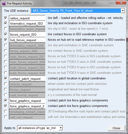
Note: | When the template contains a group of tire geometry elements for the tire belt (naming: wh[lr]_belt_graphics), this belt geometry will be visualized and attached to the belt part in case a PAC2002 tire property file is used that is using the BELT_DYNAMICS option. |
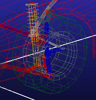
Torsion Bar Double-Wishbone Suspension
Overview
The torsion bar double-wishbone suspension template is a modified version of the standard Double-Wishbone Suspension. In this template, however, a torsion bar spring replaces the coil spring.
Figure 22 Torsion Bar Double-Wishbone Suspension
Template name
_double_wishbone_torsion
Major role
Suspension
Application
Suspension and full-vehicle assemblies
Description
In the torsion bar double-wishbone suspension template, a torsion bar spring replaces the coil spring used in the standard Double-Wishbone Suspension. The torsion bar consists of two bar halves connected by a rotational SFORCE (joint torque actuator). The rotational SFORCE exerted between the two bar halves is a function of a torsional stiffness and of the relative rotation along the torsion bar longitudinal axis.
Files referenced
Refer to the Double-Wishbone Suspension.
Topology
The torsion bar consists of two bar halves connected by a cylindrical joint and a joint torque actuator. The first half is rigidly connected to the lower control arm, and the second half is fixed to the mount part and gets rigidly connected to the chassis if you use the suspension in full-vehicle assemblies.
Parameters
The torsion bar double-wishbone suspension template includes additional parameter variables besides those described in the Double-Wishbone Suspension. The variable defining the torsional stiffness defines the torsion bar stiffness. Also, another parameter variable defines the torsional preload applied between the lower control arm and the torsion bar.
The following table lists the additional parameters.
The parameter: | Takes the value: | Its units are: |
|---|---|---|
pv[lr]_tbar_stiffness | Real | Nmm/Degrees |
pvs_tbar_preload | Real | Nmm |
Communicators
Refer to the Double-Wishbone Suspension.
Note: | The torsion bar double-wishbone suspension template includes a toe adjustment. It uses an adjustable force Adams Car element to reach a desired toe angle at static equilibrium. |
Trailing Arm Suspension
Overview
The trailing arm suspension template is one of the most simple and economical designs for independent suspensions.
Figure 23 Trailing Arm Suspension
Template name
_trailing_arm
Major role
Suspension
Application
Suspension and full-vehicle assemblies
Description
The trailing arm suspension template is a simple non-steerable suspension design. You can deactivate the driveline simply by selecting inactive in the Toggle Driveline Activity dialog box. Note that it is possible to define the spring concentric to the damper just by moving the spring upper- and lower-seat hardpoints.
Files referenced
Bushing, spring, damper, bumpstop, and reboundstop property files
Topology
Trailing arms to the left and right sides mount to a rigid subframe that in turns connects to the body mount part through bushings. The arms alone locate the wheel centers. Springs and dampers act between the arms and the body mount parts. A static rotation control actuator locks the rotational degree of freedom of the hub during quasi-static analyses.
You can set the suspension to kinematic or compliant mode. Kinematic mode allows purely kinematic connections between the upper strut parts, arms, subframe, and mount parts, while compliant mode replaces the kinematic joints with their corresponding elastic elements.
The following table maps the topology of the template.
The joint: | Connects the part: | To the part: |
|---|---|---|
jklhoo_upr_strut_to_body | mtl_strut_to_body | gel_upper_strut |
jklrev_arm_inner_ pivot | gel_arm | ges_subframe |
jksfix_subframe_to_body_fixed | ges_subframe | mts_subframe_to_body |
jklhoo_lwr_strut_to_arm | gel_lower_strut | gel_arm |
jolcyl_lwr_upr_ strut | gel_upper_strut | gel_lower_strut |
joltra_tripot_to_ differential | gel_tripot | mtl_tripot_to_differential |
jolcon_drive_sft_ int_jt | gel_tripot | gel_drive_shaft |
Hub Compliance on | ||
jolsph_hub_compliance | gel_spindle | gel_upright |
Hub Compliance off | ||
jolrev_spindle_ upright | gel_spindle | gel_upright |
Parameters
The driveline offset variable defines the driveline geometry. Toe and camber variables define wheel spin axis, spindle part, and spindle geometry.
The parameter: | Takes the value: | Its units are: |
|---|---|---|
phs_kinematic_flag | Integer | No units |
pvs_hub_compliance_active | Integer | No units |
pv[lr]_toe_angle | Real | Degrees |
pv[lr]_drive_shaft_offset | Real | mm |
phs_driveline_active | Integer | No units |
pv[lr]_camber_angle | Real | Degrees |
pvs_hub_compliance_offset | Real | mm |
Communicators
Mount parts provide the connectivity from the template to the body subsystems. Output communicators publish toe, camber, steer axis, and wheel-center location information to the appropriate subsystems and the test rig. The following table lists the input and output communicators.
The communicator: | Belongs to the class: | Has the role: |
|---|---|---|
ci[lr]_spring_to_body | mount | inherit |
ci[lr]_strut_to_body | mount | inherit |
ci[lr]_tripot_to_differential | mount | inherit |
cis_subframe_to_body | mount | inherit |
co[lr]_camber_angle | parameter_real | inherit |
co[lr]_ride_height_ref | marker | inherit |
co[lr]_suspension_mount | mount | inherit |
co[lr]_suspension_upright | mount | inherit |
co[lr]_toe_angle | parameter_real | inherit |
co[lr]_tripot_to_differential | location | inherit |
co[lr]_wheel_center | location | inherit |
cos_driveline_active | parameter_integer | inherit |
cos_suspension_ parameters_ARRAY | array | inherit |
Note: | The integer parameter variables let you activate and deactivate the Hub Compliance. The kinematic flag variable toggles between kinematic and compliant mode. |
Twist Beam Suspension
Overview
The twist beam suspension is a dependent suspension model intended for use only as a rear suspension. It does not include a panhard rod.
Figure 24 Twist Beam Suspension
Template name
_twist_beam
Major role
Suspension
Application
Suspension and full-vehicle assemblies
Description
The twist beam suspension template represents a common rear dependent suspension design. It does not include a subframe. The suspension is non-steerable and intended to be used as a rear suspension only.
The twist beam is a flexible body generated using shell elements. Interface parts connect the flexible body to the rest of the suspension.
You can toggle the suspension between kinematic and compliant modes. In addition, you can deactivate driveshafts.
Files referenced
Springs, dampers, and bushings property files. Also, the flexible body references the file PonteV.mnf, stored in the flex_bodies.tbl directory of the Adams Car shared database.
Topology
A static rotation control actuator locks the rotational degree of freedom of the hub during quasi-static analyses.
The following table maps the topology of the twist beam suspension.
The joint: | Connects the part: | To the part: |
|---|---|---|
jklhoo_upr_strut_to_body | mtl_strut_to_body | gel_upper_strut |
jolcyl_lwr_upr_strut | gel_upper_strut | gel_lower_strut |
joltra_tripot_to_differential | gel_tripot | mtl_tripot_to_differential |
jolcon_drive_sft_int_jt | gel_tripot | gel_drive_shaft |
jolcon_drive_sft_otr | gel_drive_shaft | gel_spindle |
jolhoo_strut_to_beam | gel_lower_strut | ipl_damper_lwr |
jklrev_beam_to_body | ipl_beam_to_subframe | mts_body |
Hub Compliance on | ||
jolsph_hub_compliance | gel_spindle | ipl_spindle_to_beam |
Hub Compliance off | ||
jolrev_spindle_to_beam | gel_spindle | ipl_spindle_to_beam |
Parameters
In the twist beam suspension, toe and camber variables parameterize wheel spin axis, spindle part, and spindle geometry. The following table lists the parameters in the template.
The parameter: | Takes the value: | Its units are: |
|---|---|---|
phs_driveline_active | Integer | No units |
phs_kinematic_flag | Integer | No units |
pvs_hub_compliance_active | Integer | No units |
pv[lr]_toe_angle | Real | Degrees |
pv[lr]_camber_angle | Real | Degrees |
pv[lr]_drive_shaft_offset | Real | mm |
pvs_hub_compliance_offset | Real | mm |
Communicators
The following table lists the communicators in the template.
The communicator: | Belongs to the class: | Has the role: |
|---|---|---|
ci[lr]_spring_to_body | mount | inherit |
ci[lr]_strut_to_body | mount | inherit |
ci[lr]_tripot_to_differential | mount | inherit |
cis_body | mount | inherit |
co[lr]_camber_angle | parameter_real | inherit |
co[lr]_ride_height_ref | marker | inherit |
co[lr]_suspension_mount | mount | inherit |
co[lr]_toe_angle | parameter_real | inherit |
co[lr]_tripot_to_differential | location | inherit |
co[lr]_wheel_center | location | inherit |
cos_driveline_active | parameter_integer | inherit |
cos_suspension_parameters_ARRAY | array | inherit |
Note: | The integer parameter variables let you activate and deactivate the driveshafts and the Hub Compliance. The kinematic flag variable toggles between kinematic and compliant mode. |
Wheel Forces
Overview
The wheel forces template is intended to be used with a General Actuation Analysis. The wheel forces template provides three forces and three moments to four wheel parts that you assemble with your full-vehicle model.
Figure 25 Wheel Forces Template
Template name
_wheel_forces
Major role
Wheel
Application
General Actuation analyses
Description
The wheel forces template consists of wheel parts that are actuated by user input functions. For additional information about using this template, see the General Actuation Analysis feature examples.
Topology
Six wheel forces are applied to each wheel part. Fixed joints connect the wheel parts to each spindle mount part. The vehicle body may be fixed or free depending on which communicators match during assembly. Steering motion is applied to the steering wheel joint.
Communicators
Mount parts provide connectivity to the suspension, body, and steering subsystems.
The following table lists the communicators in the tire system template.
The communicator: | Belongs to the class: | Has the role: |
|---|---|---|
ci[lr]_camber_angle_front | parameter_real | front |
ci[lr]_camber_angle_rear | parameter_real | rear |
ci[lr]_spin_axis_front | mount | front |
ci[lr]_spin_axis_rear | mount | rear |
ci[lr]_toe_angle_front | parameter_real | front |
ci[lr]_toe_angle_rear | parameter_real | rear |
ci[lr]_wheel_center_front | location | front |
ci[lr]_wheel_center_rear | location | rear |
cis_Body | mount | inherit |
cis_Body_fix | mount | inherit |
cis_steering_wheel_joint | joint_for_motion | inherit |