GSE Damper
To use a GSE damper, you must have a license for Adams Controls.
Adams's system modeling elements enable the modeling and importing of external dynamic systems. Those elements make it possible for users to define transfer functions, linear state equations, and nonlinear state equations outside of Adams, and then input them for use with Adams. Among those, the general state equation (GSE) is designed to model and import nonlinear external dynamic systems, such as a damper.
The GSE damper provided with Adams Car Ride illustrates a simple ride-based damper that has been created within Mathworks® Simulink® and exported using Matlab Code Generation. The GSE damper provides a framework that you can use to import proprietary damper models into Adams Car Ride.
For more information on importing the object code of the damper, see the guide, Getting Started Using Adams Controls.
Learn more about GSE dampers:
Scope
Provided with Adams Car Ride is a complete set of files that you can use with Mathworks Simulink and Adams Car Ride to incorporate and test the functionality of the GSE damper. A license of Mathworks Simulink and appropriate compilers is required to carry out this process. If, however, another user provides you with a library (.dll, .so, or .sl, depending on your platform), you will only need a license of Adams Controls and Adams Car Ride to run an analysis within Adams.
This topic provides a guide to using the GSE damper component. It does not explain how to use Mathworks Simulink or how to export a library using Code Generation.
Results
When you create a GSE damper, Adams Car Ride automatically creates some associated REQUEST statements. These requests measure the displacement, velocity, and force across the damper.
Parametric Studies
As with all elements, in Adams Car Ride you can study the parametric behavior of components. You can modify a number of parameters for use in Adams Insight. The parameter data is stored in the corresponding subsystem file.
Solver Background
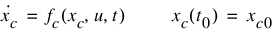
A General State Equation (GSE) is an Adams element designed for time-variant, nonlinear, continuous or discrete dynamic systems, which can be mathematically represented as follows:
(1)
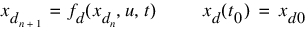
(2)
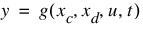
(3)
....
The definition of GSEs contains two portions:
■GSE statement in the model: Provides the interface with Adams model, and specifies the attributes of the imported dynamic system.
■GSE library: A library of code written to the Adams GSE specification. For more information on general state equations, see the online help for Adams Solver.
Benefits of External Dynamic System Import
Embedding external dynamic systems into Adams allows the use of a unified platform for multi-domain analyses, and provides the following advantages over a cosimulation-based approach:
■Faster speed: Powerful Adams integrators can simulate the stiff combined systems at a speed unmatched by function-evaluation mode in Adams Controls.
■Higher accuracy: Because the external dynamic systems and the Adams model are incorporated into one formulation, the dynamic coupling between them can be precisely represented, and its effect is taken into account during the simulation. The accuracy achieved with external dynamic systems imported is unparalleled compared to those from cosimulation and function-evaluation mode.
■DOE with Adams Insight
■Protecting proprietary code: Because the external dynamic systems can be imported in the form of an object file and demand-loaded library, the proprietary code is not exposed.
However, to create both the GSE statement and the demand-load library manually, you need a high level of programming skills and a deep understanding of Adams Solver. To facilitate the creation of the GSE, an external system import utility is designed as a feature of the GSE damper element to import the external dynamic systems code.
Control System Import
The Control System Import performs the following steps:
1. Creates a library.
2. Queries the library to be imported for the information used to update the GSE statement of the GSE damper element. The external dynamic system library should provide information, such as number of states, inputs and outputs, and the tunable parameter.
3. Performs an error check to ensure that the external system complies with the standard required by the GSE damper element.
4. Generates a property file in the default writable database, which contains the parameters of your Simulink model.
During the simulation, the demand-loaded library is loaded into and called by Adams Solver to provide derivatives of states and output for Adams Solver to integrate.
A set of example files is located in the shared_ride_database.cdb/gse_damper.tbl.
Simulink Damper Model
This section teaches you how to generate an External System Library (ESL) for a damper designed in MATLAB/Simulink and import them into Adams Car Ride. Adams Controls is required to use this feature, and uses a similar, but more generalized process of Control System Import. Please refer Adams Controls for further details of the general method of importing models from Simulink or Easy5.
A Simulink damper model can be used when you want to model proprietary dampers in Adams. Due to the customized process in Adams Car Ride, the damper model must have three inputs, in the following order:
■Displacement
■Velocity
■Acceleration between the markers I and J.
Inputs not required by the Simulink model must be terminated with a terminator block. The model must have one output, which is the force from the Simulink modal of the damper to be applied in the Adams model. The inputs and output are in Adams modeling units. The sample Simulink file damper_example_tf.mdl is provided in Aride shared database under gse_damper.tbl folder for demonstration.
Following are the basic steps one has to perform to use Simulink damper in Adams:
Step One - Replace Damper with GSE_Damper
First you will start Adams Car and open component test rig, and then perform a Replace operation to create a GSE_Damper.
To start Adams Car and open component test rig:
1. Launch Adams Car.
2. Load the Adams Car Ride plug-in, if not already loaded and open the assembly: component_damper_example.asy
3. Use Replace feature in Aride to replace Damper with GSE_damper
(Right click the assembly and select Damper:component_damper_001.das_dar_ride_damper -> Replace)
This is required to create the input and output state variables for the damper model in Simulink.
Step Two - Export the Plant File for MATLAB
In this section, you will export the Adams linear and nonlinear plant files to MATLAB.
 to launch the
2. Complete the dialog box as shown below.
3. Click OK.
Adams Controls save the input and output information in a gse_damper.m file under working directory
Step Three - Setup MATLAB
First you will start MATLAB, and then you will create a Simulink model for control system design. You will use the Plant Export.m file to setup MATLAB, as well as the example_damper_tf model files supplied in Aride shared database,
To start MATLAB:
1. Start MATLAB in the same directory as on the model and Simulink files reside.
2. Set up the MEX utility, if not already set.
Enter mex -setup from the MATLAB command window, and then select the appropriate compiler. (see http://simcompanion.hexagon.com under Hardware & Software Requirements for a list of supported compilers)
3. At the prompt (>>), enter gse_damper
MATLAB displays the following:
%%% INFO : ADAMS plant actuators names :
1 component_damper_001.das_dar_ride_damper.force_state
%%% INFO : ADAMS plant sensors names :
1 component_damper_001.das_dar_ride_damper.displacement_state
2 component_damper_001.das_dar_ride_damper.velocity_state
3 component_damper_001.das_dar_ride_damper.acceleration_state
4. At the prompt, enter who to view the list of variables defined in the files.
MATLAB displays the following relevant information:
ADAMS_cwd | ADAMS_mode | ADAMS_solver_type | ans |
ADAMS_exec | ADAMS_outputs | ADAMS_static | arch |
ADAMS_host | ADAMS_pinput | ADAMS_sysdir | flag |
ADAMS_init | ADAMS_poutput | ADAMS_uy_ids | machine |
ADAMS_inputs | ADAMS_prefix | ADAMS_version | topdir |
You can check any of the above variables by entering them at the MATLAB prompt. For example, if you enter Adams_outputs, MATLAB displays all of the outputs defined for your mechanism, that is: ADAMS_outputs = displacement_state!velocity_state!acceleration_state.
Step Four - Create Adams Target for Matlab Code Generation
In order to generate the External System Library from the MATLAB/Simulink model, you need to generate some special files for MATLAB Code Generation. You will customize the Makefile template and source code template for Adams, based on the version of MATLAB. Once this is done, you can use the customized template files for other Simulink models.
To create the Code Generation files for the Adams Controls model:
1. At the MATLAB prompt (>>), enter setup_rtw_for_adams
This will automatically detect the version of Matlab you are using and then create the makefile template, source code template for Adams. This function will also build template for specific versions of Matlab if desired by entering the desired version token as an argument: setup_rtw_for_adams('<version>')). For help on this, enter setup_rtw_for_adams('h').
You should see the following message for success in this step:
%%% Successfully created files in the working directory needed for Adams library export.
You should also confirm that in your working directory that .tlc and .tmf files were created by this step.
Alternatively, since the function setup_rtw_for_adams also uses process.py, you can still setup using the old method:
(Optional method if not using setup_rtw_for_adams function)
a. Set the MATLAB_ROOT environment variable to the MATLAB installation directory. For example:
♦On Windows (DOS shell): set MATLAB_ROOT= c:\matlab78\
♦On Linux (c shell): setenv MATLAB_ROOT /usr/matlab_78/
♦On Linux (korn shell): export MATLAB_ROOT = /usr/matlab_78/
♦Change the directory paths to match your installation.
b. In the directory where your Adams model resides, enter the following command, where $adams_dir is the directory in which Adams is installed:
♦On Linux: adams2024_1 -c python ($adams_dir)/controls/utils/process.py -v 78 exit
♦On Windows: adams2024_1 python ($adams_dir)\controls\utils\process.py -v 78
Alternatively, you can copy the process.py file from the <adams_dir>/controls/utils/ directory on Linux or <adams_dir>\controls\utils\ on Windows to the current directory and issue the following command:
♦On Linux: adams2024_1 -c python process.py -v 78 exit
♦On Windows: adams2024_1 python process.py -v 78
The argument -v 78 stands for MATLAB 7.8 (R2009a).
This command customizes several files from the MATLAB installation for the Adams target and your computer setup. You should notice several new files in your working directory with a .tlc extension and two new files with a .tmf extension. These files required by MATLAB's Code Generation in the steps that follow. For help with process.py, use the -h flag (that is, process.py -h).
Note: | The value for MATLAB_ROOT should have no quote, no spaces (on Windows, get short names with command dir /x), and a final slash on the path. For example, if you want to set C:\Program Files\matlab78\ as your MATLAB_ROOT, then do it as: set MATLAB_ROOT= C:\PROGRA~1\matlab78\ |
Step Five - Create Simulink Model
To create the Simulink template for the control system:
1. Enter setio at the MATLAB prompt.
MATLAB creates a template model with the inport(s) and outport(s) defined, as shown below.
Based on this template, you can design your proprietary damping systems. These files you already copied into the local directory.
2. Rather creating a new model, use the example found in the Adams Car Ride shared database (<aride_shared>/gse_dampers.tbl/damper_example_tf.mdl). To open damper_example_tf.mdl, from the File menu, select Open. Or, double-click the file in the file browser.
In the following context, the damper control system will be used as the example to illustrate the process. Following figure shows the damper Simulink model provided and its associated plant input and outputs.
Step Six -Code Generation of Simulink Damper Model (Control System)
First you will configure MATLAB Code Generation and then you will create the External System Library from the Simulink model. Given a controller designed with the appropriately designated inports and outports, the following steps are required to export the model using Matlab Code Generation.
1. From the Code menu, point to Code Generation.
The Simulation Parameters dialog box appears.
2. Verify Generate code only option is not selected.
3. Select Browse next to System target file and choose the rsim.tlc target.
The completed Simulink Parameters dialog box should look as shown below.
4. From the treeview on the left side of the window, select Solver.
The dialog box displays the Solver options as shown below
5. Set Solver options Type to Variable-Step. (If selecting Fixed-Step solver, set Mode to SingleTasking.)
6. Under zero-crossing options, set Zero-crossing to Disable All.
The completed Simulink Parameters dialog box should look as shown below.
7. From the treeview on the left side of the window, select Optimization → Signals and Parameters.
The dialog box displays the options as shown in below figure.
8. Verify Inline parameters options is selected. Enabling Inline parameters has the following effects:
■Code Generation uses the numerical values of model parameters, instead of their symbolic names, in generated code.
■Reduces global RAM usage, because parameters are not declared in the global parameters structure.
9. Select "Configure…" button to open the Model Parameters Configuration dialog box and verify that parameters ReboundDamping and CompressionDamping are selected as Global (tunable) parameters. This will allow Adams to create design variables for these parameters.
10. Select OK to close the Model Parameters Configuration dialog box.
11. Click Apply.
12. Define the parameters in MATLAB workspace by issuing the following
ReboundDamping = 100;
CompressionDamping = 200;
(You can access the two MATLAB variables from the Simulink model by double-clicking them.)
13. To begin code generation and build the Code Generation library, from the main menu select Code → Build Model
The library you created will be in your working directory.
Step Seven - Select the Damper Library and Simulate
First you will start Adams Car and open component test rig, and then simulate your Adams model containing the GSE for the control system.
To start Adams Car and import External System Library (ESL):
1. If you haven't already done then launch Adams Car
2. Load the Adams Car Ride plug-in, if not already loaded and open the assembly: component_damper_example.asy
3. Use Replace feature in Aride to replace Damper with GSE_damper
(Right click the assembly and select Damper:component_damper_001.das_dar_ride_damper -> Replace)
4. Click OK. This will launch the Modify GSE Damper dialog box. If not, Right Click Damper: component_damper_001.das_dar_ride_damper and select Modify
5. Click the  to import the External System Library (ESL) for the damper. This will launch a GSE Damper Code Import dialog box.
to import the External System Library (ESL) for the damper. This will launch a GSE Damper Code Import dialog box. 6. Right-click the Library to be imported field, and select Browse. Choose damper_example_tf.[dll,so]
7. Click the Property file name field and enter "damper_example_tf"
This will create a properly file for the ESL and will automatically update the Property File filed of Modify GSE Damper dialog to point it.
To run simulation and plot GSE_damper force:
1. From the Ride menu, point to Component Analysis, and then select Component-Model Test Rig …
The Adams Car Ride Component Analysis dialog box appears.
(Please refer Aride Component Analysis help to do Component Analysis.)
2. Plot the force from GSE damper force in Adams Post Processor
Note: | If your model has multiple instances of a gse damper, and using the same library, then you need to give different library names. |