Templates Overview
msc_truck_airspring_drive_axle
Overview
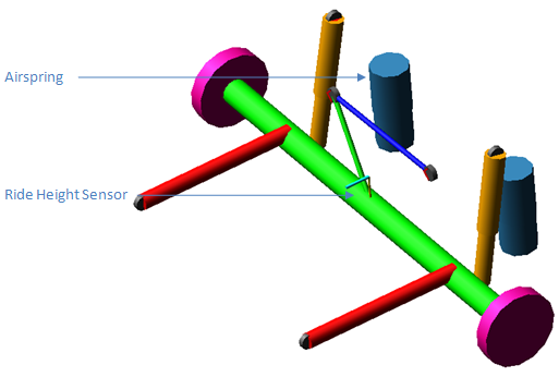
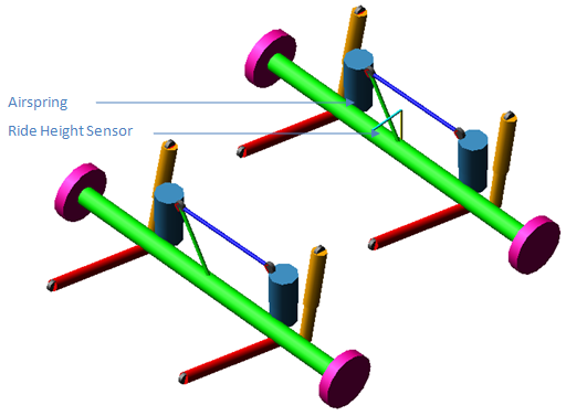
This template represents the solid axle suspension typically used on tractors and buses. This template is identical to the msc_truck_drive_axle template except for the addition of a ride height sensor and the airsprings.
Template name
_msc_truck_airspring_drive_axle
Major role
Suspension
Application
Suspension and Full-vehicle analysis
Description
The template is an alternative to msc_truck_drive_axle. This version uses truck airsprings in conjunction with a ride height sensor.
Files referenced
msc_truck_airspring.xml
mdi_viscous.dif
mdi_0001.bus
mdi_0001.dpr
Topology
The topology is identical to the msc_truck_drive_axle template, with the exception of the ride height sensor.
The following table maps the additional topology of this template:
The joint: | Connects the part: | To the part: |
|---|---|---|
ues_rhs.ride_height_arm2frame | ues_rhs.arm | mts_panhard_rod_to_frame |
ues_rhs.ride_height_arm2link | ues_rhs.arm | ues_rhs.link |
ues_rhs.ride_height_link2axle | ues_rhs.link | ges_panhard_link |
Parameters
There are no additional parameters in this template.
Communicators
There are no additional communicators in this template.
msc_truck_airspring_tandem_drive_axle
Overview
This template represents the solid twin axle suspension typically used on tractors. This template is identical to the msc_truck_tandem_drive_axle template except for the addition of a ride height sensor and the airsprings.
Template name
_msc_truck_airspring_tandem_drive_axle
Major role
Suspension
Application
Suspension and Full-vehicle analysis
Description
The template is an alternative to msc_truck_tandem_drive_axle. This version uses truck airsprings in conjunction with a ride height sensor.
Files referenced
msc_truck_airspring.xml
mdi_viscous.dif
mdi_0001.bus
msc_truck_trailing_arm_to_frame.bus
msc_truck_panhard_rod_to_frame.bus
msc_truck_panhard_rod_to_axle.bus
msc_truck_drive_axle.dpr
Topology
The topology is identical to the msc_truck_tandem_drive_axle template, with the exception of the ride height sensor.
The following table maps the additional topology of this template:
The joint: | Connects the part: | To the part: |
|---|---|---|
ues_rhs.ride_height_arm2frame | ues_rhs.arm | mts_panhard_rod_to_frame_2 |
ues_rhs.ride_height_arm2link | ues_rhs.arm | ues_rhs.link |
ues_rhs.ride_height_link2axle | ues_rhs.link | ges_panhard_link_2 |
Parameters
There are no additional parameters in this template.
Communicators
There are no additional communicators in this template.
msc_truck_rigid_cab
Overview
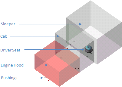
This template represents the cab of the tractor.
Template name
_msc_truck_rigid_cab
Major role
cab
Application
Full-vehicle analysis
Description
The cab consists of three boxes representing the engine, driver and sleeping compartments. The cab suspension and bushings mount the cab on a rigid tractor frame.
Files referenced
mdi_0001.bus
msc_truck_driver_seat.bus
Topology
The following table maps the topology of the template:
The joint: | Connects the part: | To the part: |
|---|---|---|
jksfix_hood_to_cab | ges_hood | ges_cab |
jksfix_cab_to_frame | ges_cab | mtr_cab_mount |
bg[lr]_front_seat_to_cab_bushing.field | ges_cab | ges_driver_seat |
bg[lr]_rear_seat_to_cab_bushing.field | ges_cab | ges_driver_seat |
bk[lr]_front_cab_mount.field | mt[lr]_cab_mount | ges_cab |
bk[lr]_hood_frame.field | mt[lr]_hood_frame_mount | ges_hood |
bk[lr]_hood_to_cab.field | ges_cab | ges_hood |
bks_hood_to_cab_center.field | ges_cab | ges_hood |
Parameters
None
Communicators
Mount parts provide the connectivity between the template and cab_suspension subsystems.
Input communicators receive information about mounting of the cab on rigid_tractor frame. The output communicators define the cab_suspension location, main exhaust and steering column support.
Input communicators receive information about mounting of the cab on rigid_tractor frame. The output communicators define the cab_suspension location, main exhaust and steering column support.
The following table lists the communicators in the template.
The communicator: | Belongs to the class: | Has the role: |
|---|---|---|
ci[lr]_cab_mount | mount | inherit |
ci[lr]_hood_frame_mount | mount | inherit |
co[lr]_cab_suspension_shocks | mount | inherit |
co[lr]_main_exaust_to_cab | mount | inherit |
co[lr]_stack_to_cab | mount | inherit |
cos_cab_suspension | mount | inherit |
co[lr]_steering_column_to_body | mount | inherit |
msc_truck_cab_suspension
Overview
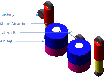
This template provides connection between the cab and the rigid_tractor frame.
Template name
_msc_truck_cab_suspension
Major role
cab_suspension
Application
Full-vehicle analysis
Description
This template represents the main cab suspension unit. A truck cab is isolated from the tractor frame by means of a combination of springs and dampers. Upper and lower mount parts are connected to the cab frame and the tractor frame, respectively. A longitudinal rod is used to connect the cab to the frame and to react loads in that direction
Files referenced
msc_truck_cab_suspension_lateral_bar.bus
msc_truck_cab_suspension_shock.dpr
msc_truck_cab_suspension_shock.bus
msc_truck_cab_suspension_airspring.spr
Topology
Lower and upper shock parts are connected via a cylindrical joint. Fixed joints are used to connect lower airbag parts to the mounts.
The following table maps the topology of the template.
The joint: | Connects the part: | To the part: |
|---|---|---|
ge[lr]_upper_shock | ge[lr]_upper_shock | ge[lr]_lower_shock |
jo[lr]fix_lower_airbag_to_mount | ge[lr]_lower_airbag | mt[lr]_lower_airbag_to_frame |
jo[lr]fix_upper_airbag_to_mount | ge[lr]_upper_airbag | mt[lr]_upper_airbag_to_cab |
bg[lr]_lower_shock_to_mount.field | ge[lr]_lower_shock | mt[lr]_shock_to_frame |
bg[lr]_upper_shock_to_mount.field | ges_lateral_bar | ge[lr]_upper_shock |
bgs_left_lateral_bar_to_mount.field | ge[lr]_upper_shock | mts_lateral_rod_to_frame |
bgs_right_lateral_bar_to_mount.field | ges_lateral_bar | mts_lateral_rod_to_cab |
da[lr]_shock_damper.force | mt[lr]_shock_to_cab | mt[lr]_shock_to_frame |
ns[lr]_airbag_spring.force | mt[lr]l_upper_airbag_to_cab | mt[lr]_lower_airbag_to_frame |
ns[lr]_airbag_spring.spdp_force | mt[lr]_upper_airbag_to_cab | mt[lr]_lower_airbag_to_frame |
Parameters
None
Communicators
Mount parts provide connectivity between the template and the cab and rigid_tractor, subsystems.
Input communicators receive information about the shock absorber, spring and bumpstop locations, etc. There are no output communicators.
Input communicators receive information about the shock absorber, spring and bumpstop locations, etc. There are no output communicators.
The following table lists the communicators in the template:
The communicator: | Belongs to the class: | Has the role: |
|---|---|---|
ci[lr]_lower_airbag_to_frame | mount | inherit |
ci[lr]_shock_to_cab | mount | inherit |
ci[lr]_shock_to_frame | mount | inherit |
ci[lr]_upper_airbag_to_cab | mount | inherit |
cis_lateral_rod_to_cab | mount | inherit |
cis_lateral_rod_to_frame | mount | inherit |
cis_lower_bump_stop_to_frame | mount | inherit |
cis_upper_bump_stop_to_cab | mount | inherit |
msc_truck_rigid_tractor
Overview
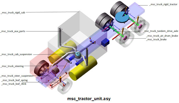
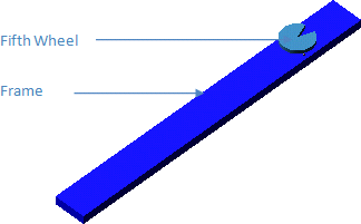
The template represents a frame with integrated fifth wheel to which the subassemblies like cab, suspension and drive axles, etc. are attached.
Template name
_msc_truck_rigid_tractor
Major role
Body
Application
Full-vehicle analyses
Description
The rigid tractor system forms the basic frame of the tractor to which the cab, suspension and other subassemblies connect through flexible couplings (bushing). The trailer is hitched to the tractor through the fifth wheel.
Files referenced
msc_truck_fifth_wheel_frame.bus
fifth_wheel.shl
Topology
The template contains information about the frontal area, air density and drag coefficient which is used to calculate the aerodynaminc drag based on the vehicle velocity. No joints are defined but a series of communicators define the attachment points for other subassemblies. The fifth wheel is connected to the tractor frame rigidly or through bushing depending on the kinematic_mode parameter.
Parameters
The parameter information in the template helps to calculate the aerodynamic drag on the vehicle for which the following parameters are specified:
The parameter: | Takes the value: | Its units are: |
|---|---|---|
pvs_aero_frontal_area | real | area |
pvs_air_density | real | density |
pvs_drag_coefficient | real | no_units |
Communicators
Single input communicator and number of output communicators define the attachment point for the subassemblies to the frame as listed below:
The communicator: | Belongs to the class: | Has the role: |
|---|---|---|
cis_std_tire_ref | location | inherit |
co[lr]_cab_mount | mount | inherit |
co[lr]_cab_susp_shock_to_frame | mount | inherit |
co[lr]_fd_shock_to_frame | mount | rear |
co[lr]_fd_spring_to_frame | mount | rear |
co[lr]_fifth_wheel_to_trailer | mount | inherit |
co[lr]_fifth_wheel_to_frame | mount | inherit |
co[lr]_front_airtank_to_frame | mount | inherit |
cos_fifth_wheel_location | location | trailer |
co[lr]_front_engine_to_frame | mount | truck |
co[lr]_front_susp_leafspring_mount | mount | any |
co[lr]_front_susp_shackle_mount | mount | any |
co[lr]_front_susp_upper_shock | mount | front |
co[lr]_hood_frame_mount | mount | inherit |
co[lr]_lower_airbag_to_frame | mount | inherit |
co[lr]_lower_front_fueltank_to_frame | mount | inherit |
co[lr]_lower_middle_fueltank_to_frame | mount | inherit |
co[lr]_lower_radiator_to_frame | mount | inherit |
co[lr]_lower_rear_fueltank_to_frame | mount | inherit |
co[lr]_rd_shock_to_frame | mount | rear_2 |
co[lr]_rd_spring_to_frame | mount | rear_2 |
co[lr]_rear_airtank_to_frame | mount | inherit |
co[lr]_rear_engine_to_frame | mount | inherit |
co[lr]_rear_suspension_to_frame | mount | rear_2 |
co[lr]_suspension_to_frame | mount | rear |
co[lr]_upper_front_fueltank_to_frame | mount | inherit |
co[lr]_upper_middle_fueltank_to_frame | mount | inherit |
co[lr]_upper_radiator_to_frame | mount | inherit |
co[lr]_upper_rear_fueltank_to_frame | mount | inherit |
cos_aero_drag_force | solver_variable | inherit |
cos_aero_frontal_area | parameter_real | inherit |
cos_air_density | parameter_real | inherit |
cos_body_subsystem | mount | inherit |
cos_chassis_path_reference | marker | inherit |
cos_drag_coefficient | parameter_real | inherit |
cos_driver_reference | marker | inherit |
cos_fd_panhard_rod_to_frame | mount | rear |
cos_lateral_rod_to_frame | mount | any |
cos_lower_back_bbox_to_frame | mount | inherit |
cos_lower_bump_stop_to_frame | mount | inherit |
cos_lower_front_bbox_to_frame | mount | inherit |
cos_main_exhaust_to_frame_1 | mount | inherit |
cos_main_exhaust_to_frame_2 | mount | inherit |
cos_main_exhaust_to_frame_3 | mount | inherit |
cos_main_exhaust_to_frame_4 | mount | inherit |
cos_main_exhaust_to_frame_5 | mount | inherit |
cos_main_exhaust_to_frame_6 | mount | inherit |
cos_main_exhaust_to_frame_7 | mount | inherit |
cos_main_exhaust_to_frame_8 | mount | inherit |
cos_measure_for_distance | marker | inherit |
cos_pitman_mount | marker | inherit |
cos_powertrain_to_body | mount | truck |
cos_press_valve_link_to_frame | mount | inherit |
cos_rd_panhard_rod_to_frame | mount | rear_2 |
cos_upper_back_bbox_to_frame | mount | inherit |
cos_upper_front_bbox_to_frame | mount | inherit |
msc_truck_rigid_trailer
Overview
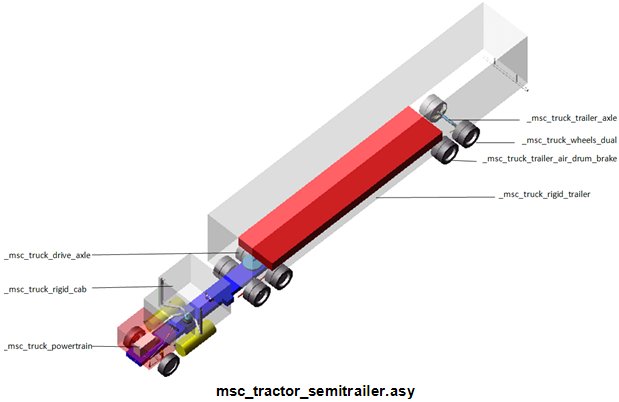
The template represents a trailer frame similar to the tractor frame which carries the payload and is hitched to the tractor through the fifth wheel.
Template name
_msc_truck_rigid_trailer
Major role
Trailer
Application
Full-vehicle analyses
Description
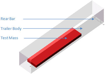
The rigid trailer system forms the basic frame of the trailer which is hitched to the tractor through the fifth wheel. The trailer is connected next to the trailer axle through rear suspension.
Files referenced
mdi_0001.bus
Topology
The template contains information about the joint location of the fifth wheel and the attachment point for the suspension shock-absorbers. The paylod (test mass) is connected through a fixed joint to the trailer body.
A stake force connects the fifth wheel mount and trailer body which is responsible for the angle between the tractor and trailer during cornering.
Parameters
The following parameters are specified in the template:
The parameter: | Takes the value: | Its units are: |
|---|---|---|
pvs_Leg_from_bulkhead | real | length |
pvs_Trailer_height | real | length |
pvs_Trailer_width | real | length |
pvs_Trailer_length | real | length |
Communicators
A single input communicator and a number of output communicators define the attachment point for the subassemblies to the frame as listed below:
The communicator: | Belongs to the class: | Has the role: |
|---|---|---|
cis_fifth_wheel_location | location | inherit |
cis_fifth_wheel_to_trailer | mount | inherit |
co[lr]_Fr_airbag_frame | mount | trailer |
co[lr]_Fr_Shock_top | mount | trailer |
co[lr]_Fr_Trail_a_frame | mount | trailer |
co[lr]_Rr_airbag_frame | mount | trailer_2 |
co[lr]_Rr_Shock_top | mount | trailer_2 |
co[lr]_Rr_trail_a_frame | mount | trailer_2 |
msc_truck_aux_parts
Overview
This template provides connection between auxiliary parts with the tractor cab and frame.
Template name
_msc_truck_aux_parts
Major role
aux_parts
Application
Full-vehicle analysis
Description
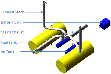
Air tanks and other rigid bodies are attached to the mount parts via bushings. There are no joints present in the model. Mount parts defined in this template connect to other templates, in particular to the cab (main exhaust pipes) and to the tractor.
Files referenced
msc_truck_left_stack.shl
msc_truck_right_stack.shl
msc_truck_main_exhaust.shl
msc_truck_airtank_to_frame.bus
msc_truck_fueltank_to_frame.bus
msc_truck_exhaust.bus
Topology
All the auxiliary components like exhaust, air tank, fuel tank, etc. are rigidly attached to the cab and tractor frame using fixed or flexible joints.
Parameters
None
Communicators
Mount parts provide the connectivity between the template and the cab, rigid_tractor subsystems. Input communicators receive information about the airtank, fuel tank and exaust mounting. There are no output communicators.
The following table lists the communicators in the template:
The communicator: | Belongs to the class: | Has the role: |
|---|---|---|
ci[lr]_front_airtank_to_frame | mount | inherit |
ci[lr]_lower_front_fueltank_to_frame | mount | inherit |
ci[lr]_lower_middle_fueltank_to_frame | mount | inherit |
ci[lr]_lower_rear_fueltank_to_frame | mount | inherit |
ci[lr]_main_exhaust_to_cab | mount | inherit |
ci[lr]_rear_airtank_to_frame | mount | inherit |
ci[lr]_stack_to_cab | mount | inherit |
ci[lr]_upper_front_fueltank_to_ | mount | inherit |
ci[lr]_upper_middle_fueltank_to_frame | mount | inherit |
ci[lr]_upper_rear_fueltank_to_frame | mount | inherit |
cis_lower_back_bbox_to_frame | mount | inherit |
cis_lower_front_bbox_to_frame | mount | inherit |
cis_main_exhaust_to_frame_1 | mount | inherit |
cis_main_exhaust_to_frame_2 | mount | inherit |
cis_main_exhaust_to_frame_3 | mount | inherit |
cis_main_exhaust_to_frame_4 | mount | inherit |
cis_main_exhaust_to_frame_5 | mount | inherit |
cis_main_exhaust_to_frame_6 | mount | inherit |
cis_main_exhaust_to_frame_7 | mount | inherit |
cis_main_exhaust_to_frame_8 | mount | inherit |
cis_upper_back_bbox_to_frame | mount | inherit |
cis_upper_front_bbox_to_frame | mount | inherit |
msc_truck_leaf_spring
Overview
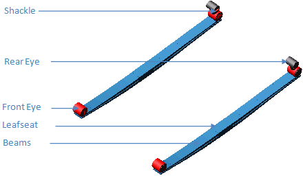
The leaf spring template is a representation of the conventional semi-elliptical suspension spring used in a solid axle vehicle.
Template name
_msc_truck_leaf_sping
Major role
suspension
Application
Suspension and full vehicle assemblies
Description
The leaf laminates are formed by a series of discrete elements coupled together by beam elements. The laminates are connected to each other by a direct force vector to represent frictional and impact forces. The entire leaf spring pack can be modified using the Leaf Spring Editor.
Files referenced
msc_truck_leaf_front_to_frame.bus
msc_truck_leaf_rear_to_shackle.bus
msc_truck_leaf_shackle_to_frame.bus
msc_truck_leaf_to_axle.bus
Topology
The leaf seat mounts the leaf spring to the axle. The front eye is directly connected to the chassis through a bushing, whereas the rear eye is connected through a shackle with intermediate bushings.
Parameters
Contains no parametric information
Communicators
Mount parts provide the connectivity between the template and body subsystems.
Input communicators receive information about the front and rear mount parts. The output communicator provides the information to mount the leaf seat to the axle.
Input communicators receive information about the front and rear mount parts. The output communicator provides the information to mount the leaf seat to the axle.
The following table lists the communicators in the template:
The communicator: | Belongs to the class: | Has the role: |
|---|---|---|
ci[lr]_shackle_to_frame | mount | inherit |
ci[lr]_leaf_to_frame | mount | inherit |
co[lr]_leaf_to_axle | mount | inherit |
msc_truck_leaf_tandem_susp_fore
Overview
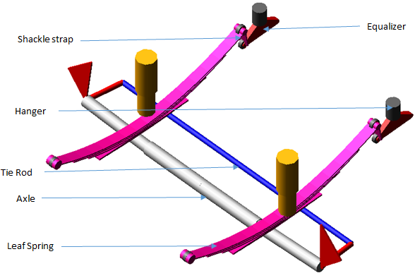
This template represents the solid axle leaf spring type suspension. This template is identical to the msc_truck_steer_suspension template except for the addition of a leaf spring, tandem axle equalizer unit, and optional panhard rod and trailing arms.
Template name
_msc_truck_leaf_tandem_susp_fore
Major role
suspension
Application
Suspension and Full-vehicle analyses
Description
This template represents the combination of msc_truck_steer_suspension and a leaf spring.
In addition, this template includes an equalizer unit. The equalizer unit contains an equalizer part, hanger, and shackle strap.
An equalizer is used for multi-axle or tandem axle suspension systems. The basic function of an equalizer is to transfer load from the heavily loaded axle to the lightly loaded axle in bump or rebound condition. The transfer of load serves to equalize the weight being carried by all axles at the time of impact.
An equalizer allows for a smooth transfer of loads through the suspension system. Without an equalizer, going over a bump would cause one axle to carry a disproportionate amount of weight.
Files referenced
leaf_front_bus.xml
mdi_0001.dpr
Topology
The topology is identical to the msc_truck_steer_suspension and msc_truck_leaf_spring template, except for the addition of an equalizer unit, and optional panhard rod and trailing arms.
You can set subsystems based on this template to Steerable axle or Non-Steerable axle using pvs_steerable_axle parameter variable. When pvs_steerable_axle parameter variable is set to 1, Adams Car activates tie rod part and dependent joints and deactivates the upright lock motion. Vice versa when steerable_axle parameter variable is set to 0.
The following table maps the additional and modified topology of this template:
The joint: | Connects the part: | To the part: |
|---|---|---|
bg[lr]_ shackle_to_frame | lf[lr]_shackle | ge[lr]_equalizer |
jo[lr]rev_hanger_to_equalizer | ge[lr]_equalizer | ge[lr]_hanger |
jo[lr]fix_hanger_to_body | ge[lr]_hanger | mt[lr]_hanger_to_body |
jo[lr]rev_trailing_arm_to_body | ge[lr]_trailing_arm | mt[lr]_trailing_arm_to_body |
jo[lr]sph_trailing_arm_to_axle | ge[lr]_trailing_arm | ge[lr]_axle |
joshoo_panhard_rod_to_body | ges_panhard_rod | mts_panhard_to_body |
jossph_panhard_rod_to_axle | ges_panhard_rod | ger_axle |
Parameters
The following table lists the parameters in the template.
The parameter: | Takes the value: | Its units are: |
|---|---|---|
phs_kinematic_flag | integer | no units |
pvs_hub_compliance_active | integer | no units |
pvs_panhard_rod_active | integer | no units |
pvs_steerable_axle | integer | no units |
pvs_trailing_arm_active | integer | no units |
pv[lr]_camber_angle | real | angle |
pv[lr]_toe_angle | real | angle |
pvs_hub_compliance_offset | real | length |
Communicators
The communicators are identical to the msc_truck_steer_suspension and msc_truck_leaf_spring template, with the exception of the additions in the following table:
The communicator: | Belongs to the class: | Has the role: |
|---|---|---|
ci[lr]_hanger_to_body | mount | inherit |
ci[lr]_trailing_arm_to_body | mount | inherit |
cis_panhard_to_body | mount | inherit |
co[lr]_equalizer_to_aft_shackle | mount | rear_2 |
cos_strarm_to_spindle_fore | mount | inherit |
Note: | The integer parameter variables allow you to activate and deactivate the Hub Compliance, panhard rod part and the trailing arm parts. The kinematic flag variable toggles between kinematic and compliant mode. |
msc_truck_leaf_tandem_susp_aft
Overview
This template represents the solid axle leaf spring type suspension. This template is identical to the msc_truck_leaf_tandem_susp_fore template except an equalizer unit and change in shackle location of the leaf spring.
Template name
_msc_truck_leaf_tandem_susp_aft
Major role
suspension
Application
Suspension and Full-vehicle analyses
Description
This template is identical to the msc_truck_leaf_tandem_susp_fore template except it does not include an equalizer unit.
Files referenced
leaf_front_bus.xml
mdi_0001.dpr
Topology
The topology is identical to the msc_truck_leaf_tandem_susp_fore template, with the exception of the equalizer unit topology and shackle location of leaf spring.
Parameters
The following table lists the parameters in the template.
The parameter: | Takes the value: | Its units are: |
|---|---|---|
phs_kinematic_flag | integer | no units |
pvs_hub_compliance_active | integer | no units |
pvs_panhard_rod_active | integer | no units |
pvs_steerable_axle | integer | no units |
pvs_trailing_arm_active | integer | no units |
pv[lr]_camber_angle | real | angle |
pv[lr]_toe_angle | real | angle |
pvs_hub_compliance_offset | real | length |
Communicators
The communicators are identical to msc_truck_leaf_tandem_susp_fore template, except equalizer unit communicators.
The following table maps the additional communicators of this template:
The communicator: | Belongs to the class: | Has the role: |
|---|---|---|
ci[lr]_equaliser_to_aft_shackle | mount | inherit |
cos_strarm_to_spindle_aft | mount | rear |
Note: | The integer parameter variables allow you to activate and deactivate the Hub Compliance, panhard rod part and the trailing arm parts. The kinematic flag variable toggles between kinematic and compliant mode. |
msc_truck_twin_axle_steering
Overview
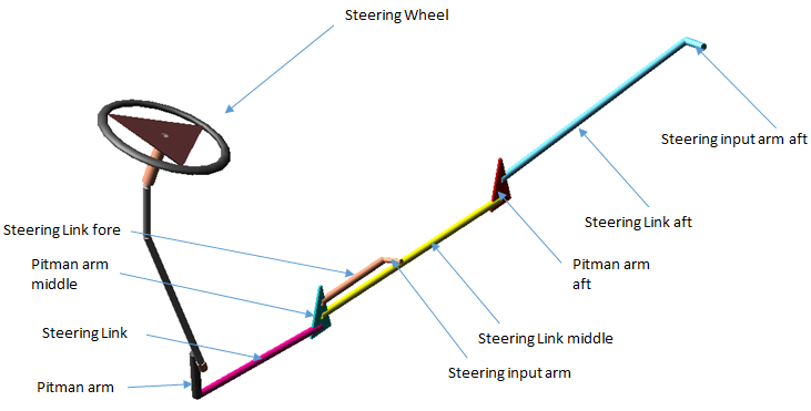
This is a simple re-circulating ball, pitman arm tandem axle steering system, with power assist. It is commonly used in heavy trucks steerable tandem axles. It consists of a three-bar mechanism: pitman arm, steering link, and steering input arm.
This template is based on the msc_truck_steering template, with the addition of pitman arms, steering link, and steering input arm for the aft axle.
Template name
_msc_truck_twin_axle_steering
Major role
steering
Application
Suspension and Full-vehicle analyses
Description
A re-circulating ball steering gear transmits motion from the steering wheel to the pitman arm. The pitman arm rotates to impart motion to the steering link.
The steering link pulls and pushes the middle pitman arm which transmits motion to steering link fore and steering link middle.
The steering link fore pulls and pushes the steering input arm which steers the fore wheels.
Steering link middle transmits motion to pitman arm aft which transmits motion to steering link aft.
The steering link aft pulls and pushes the steering input arm aft which steers the aft wheels.
Files referenced
truck_steer_assist.ste
Topology
The topology is based on the msc_truck_steering template, with the addition of pitman arm, steering link, and steering input arm for the aft axle.
The following table maps the additional and modified topology of this template:
The joint: | Connects the part: | To the part: |
|---|---|---|
jossph_steering_link_to_pitman_arm_middle | ges_steer_link | ges_pitman_arm_middle |
jossph_pitman_middle_to_steer_link_middle | ges_pitman_arm_middle | ges_steer_link_middle |
jossph_pitman_arm_middle_to_steer_link_fore | ges_steer_link_fore | ges_pitman_arm_middle |
josrev_pitman_arm_middle_to_body | ges_pitman_arm_middle | mts_pitman_arm_middle_to_body |
jossph_steer_link_aft_to_pitman_arm_aft | ges_steer_link_middle | ges_pitman_arm_aft |
jossph_pitman_arm_aft_to_steer_link_aft | ges_pitman_arm_aft | ges_steer_link_aft |
josrev_pitman_arm_aft_to_body | ges_pitman_arm_aft | mts_pitman_arm_aft_to_body |
joscon_steering_arm_aft_to_axle | ges_steer_link_aft | ges_steer_input_arm_aft |
Parameters
Parameters are identical to the msc_truck_steering template.
Communicators
The communicators are identical to the msc_truck_steering template, with additions for the aft axle.
The following table maps the additional communicators of this template:
The communicator: | Belongs to the class: | Has the role: |
|---|---|---|
cis_strarm_to_spindle_fore | mount | inherit |
cis_strarm_to_spindle_aft | mount | inherit |
cis_pitman_arm_aft_to_body | mount | inherit |
cis_pitman_arm_middle_to_body | mount | inherit |
msc_truck_leaf_3link
Overview
This template contains the SAE 3 link representation of the leafspring.
Template name
_msc_truck_leaf_3link
Major role
suspension
Application
Suspension and Full-vehicle analysis
Description
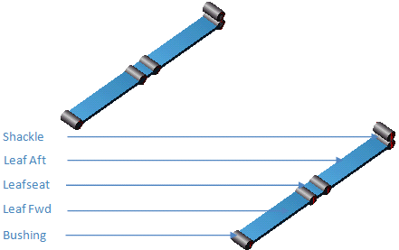
The leaf is formed by connecting three rigid sections, namely, fore, aft and leafseat.
Files referenced
mdi_0001.bus
Topology
Leafseat, fore and aft section of the single leaf are connected through bushing to form a leafspring. The fore and aft eye is then connected to the frame through bushings (with intermediate shackle at rear end ).
The following table maps the topology of the template:
The joint: | Connects the part: | To the part: |
|---|---|---|
bg[lr]_aft_leaf_attachment.field | ge[lr]l_leafseat | ge[lr]_leaf_aft |
bg[lr]_aft_leaf_bushing.field | ge[lr]_shackle | ge[lr]_leaf_aft |
bg[lr]_fwd_leaf_attachment.field | ge[lr]_leafseat | ge[lr]_leaf_fwd |
bg[lr]_fwd_leaf_bushing.field | mt[lr]_leaf_front | ge[lr]_leaf_fwd |
bg[lr]_shackle_bushing.field | mt[lr]_leaf_rear | ge[lr]_shackle |
Parameters
None
Communicators
The following table lists the communicators in the template:
The communicator: | Belongs to the class: | Has the role: |
|---|---|---|
ci[lr]_leaf_front | mount | inherit |
ci[lr]_leaf_rear | mount | inherit |
co[lr]_leaf_attach_loc | location | inherit |
co[lr]_leaf_to_axle | location | inherit |
msc_truck_steering
Overview
This is a simple re-circulating ball, pitman arm steering system, with power assist. It is commonly used in heavy trucks. It consists of a three-bar mechanism: pitman arm, steering link, and steering input arm.
Template name
_msc_truck_steering
Major role
Steering
Application
Suspension and full-vehicle assemblies
Description
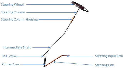
A re-circulating ball steering gear transmits motion from the steering wheel to the pitman arm. The pitman arm rotates to impart motion to the steering link. The steering link pulls and pushes the steering input arm which steers the wheels.
Files referenced
truck_steer_assist.ste
Topology
The re-circulating ball steering gear consists of three major parts:
■Input shaft
■Ball screw
■Rack
The steering wheel rotates the steering input shaft. The steering input shaft attaches to the ball screw through a torsion bar. The ball screw imparts translational motion to the rack, through a coupler. The rack, in turn, rotates the pitman arm through a coupler.
The pitman arm drags the steering link and steering input arm, which is directly connected to the left wheel, which pulls the tie rod, connected to the right wheel.
The following table maps the topology of the template:
The joint: | Connects the part: | To the part: |
|---|---|---|
joscon_input_steering_arm_to_axle | ges_steer_input_arm | ges_steer_link |
joscyl_steering_column | ges_steering_column | ges_column_housing |
joshoo_column_intermediate | ges_steering_column | ges_intermediate_shaft |
joshoo_intermediate_shaftinput | ges_intermediate_shaft | ges_input_shaft |
josrev_ball_screw_steering_gear | ges_ball_screw | mts_pitman_mount |
josrev_input_shaft_steering_gear | ges_input_shaft | mts_pitman_mount |
josrev_pitman_arm_to_frame | ges_pitman_arm | mts_pitman_mount |
josrev_steering_wheel | ges_steering_wheel | ges_column_housing |
jossph_pitman_to_draglink | ges_pitman_arm | ges_steer_link |
jostra_rack_steering_gear | ges_rack | mts_pitman_mount |
grsred_ball_screw_input_shaft_lock | josrev_input_shaft_steering_gear | josrev_ball_screw_steering_gear |
grsred_ball_screw_rack | josrev_ball_screw_steering_gear | jostra_rack_steering_gear |
grsred_pitman_arm_rack | josrev_ball_screw_steering_gear | jostra_rack_steering_gear |
grsred_pitman_arm_rack | josrev_pitman_arm_to_frame | jostra_rack_steering_gear |
grsred_steering_wheel_column_lock | josrev_steering_wheel | joscyl_steering_column |
Parameters
A parameter variable switches between kinematic and compliant mode, effectively defining the status of the ball screw input shaft lock reduction gear.
The following table lists the parameters in the template:
The parameter: | Takes the value: | Its units are: |
|---|---|---|
phs_kinematic_flag | integer | no units |
pvs_max_rack_displacement | real | length |
pvs_max_rack_force | real | force |
pvs_max_steering_angle | real | angle |
pvs_max_steering_torque | real | torque |
phs_steering_assist_active | integer | no units |
Communicators
The following table lists the communicators in the template:
The communicator: | Belongs to the class: | Has the role: |
|---|---|---|
cis_pitman_mount | mount | inherit |
cis_steering_column_to_ body | mount | inherit |
cis_strarm_to_spindle | mount | inherit |
cos_max_rack_displacement | parameter_real | inherit |
cos_max_rack_force | parameter_real | inherit |
cos_max_steering_angle | parameter_real | inherit |
cos_max_steering_torque | parameter_real | inherit |
cos_steering_rack_joint | joint_for_motion | inherit |
cos_steeing_wheel_joint | joint_for_motion | inherit |
msc_truck_steer_suspension
Overview
This template represents a steerable solid axle front suspension of a truck, and is meant to be used in conjunction with a separate template containing springs, such as _msc_truck_leaf_3link.tpl or _msc_truck_leaf_spring.tpl.
Template name
_msc_truck_steer_suspension
Major role
Suspension
Application
Suspension and Full-vehicle analysis
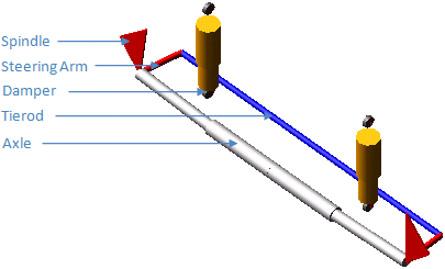
Description
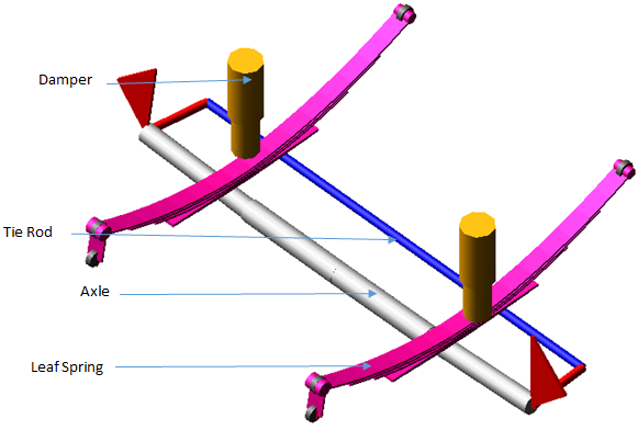
The template forms the steerable front suspension. The tie rod, steering arm and axle forms a four bar chain with two revolute and two spherical joints. The suspension upright forms the wheel carrier part. The solid axle in turn supports leafspring suspension and dampers. The steering input arm (in steering subsystem) connects to the left suspension upright.
Files referenced
msc_truck_front_susp_shock_mount.bus
msc_truck_front_susp_damper.dpr
Topology
The following table maps the topology of the template:
The joint: | Connects the part: | To the part: |
|---|---|---|
jk[lr]hoo_top_mount_kinematic | ge[lr]_upper_shock_body | mt[lr]_shock_to_frame |
jolcy[lr]_lower_upper_strut | ge[lr]_lower_shock_body | ge[lr]_upper_shock_body |
jo[lr]fix_leaf_to_axle | mt[lr]_leaf_to_axle | ge[lr]_axle |
jo[lr]sph_tie_rod_to_upright | ges_tie_rod | ge[lr]_upright |
josfix_axle | gel_axle | ger_axle |
josper_tie_rod_ori | ges_tie_rod | gel_upright |
bg[lr]_shock_to_axle.field | ge[lr]_lower_shock_body | ge[lr]_axle |
bk[lr]_shock_to_frame.field | mt[lr]_shock_to_frame | ge[lr]_upper_shock_body |
da[lr]_shock_force.force | ge[lr]_lower_shock_body | ge[lr]_upper_shock_body |
Hub Compliance on | ||
jo[lr]sph_hub_compliance | ge[lr]_spindle | ge[lr]_upright |
bg[lr]_hub_compliance | ge[lr]_spindle | ge[lr]_upright |
Hub Compliance off | ||
jo[lr]rev_axle_to_spindle | ge[lr]_spindle | ge[lr]_upright |
Parameters
The following table lists the parameters in the template:
The parameter: | Takes the value: | Its units are: |
|---|---|---|
pvs_hub_compliance_active | integer | no units |
pv[lr]_camber_angle | real | angle |
pv[lr]_toe_angle | real | angle |
pvs_hub_compliance_offset | real | length |
Communicators
Mount parts provide connectivity between the template and the rigid_cab, wheels.
Input communicators receive information about the leafspring location and attachement point for damper-to-frame. The output communicators define the wheel-center steering arm location, and suspension parameter array.
Input communicators receive information about the leafspring location and attachement point for damper-to-frame. The output communicators define the wheel-center steering arm location, and suspension parameter array.
The following table lists the communicators in the template:
The communicator: | Belongs to the class: | Has the role: |
|---|---|---|
ci[lr]_leaf_to_axle | mount | inherit |
ci[lr]_shock_to_frame | mount | inherit |
co[lr]_camber_angle | parameter_real | inherit |
co[lr]_suspension_mount | mount | inherit |
co[lr]_suspension_upright | mount | front |
co[lr]_toe_angle | parameter_real | front |
co[lr]_wheel_center | location | inherit |
cos_strarm_to_spindle | mount | front |
cos_suspension_parameters_ARRAY | array | inherit |
Note: | The integer parameter variables let you activate and deactivate the Hub Compliance. |
msc_truck_drive_axle
Overview
This template represents the solid axle suspension typically used on tractors.
Template name
_msc_truck_drive_axle
Major role
Suspension
Application
Suspension and Full-vehicle analysis
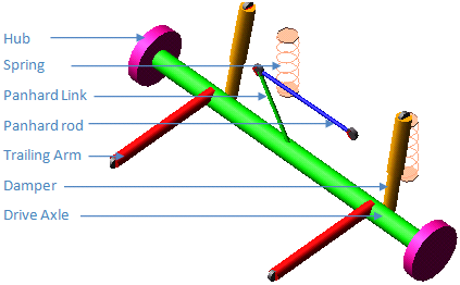
Description
The template is used in conjunction with the dual tire template in the tractor assembly as the driving solid axle. Longitudinal load is reacted by the rigid hockey sticks, and lateral load is reacted by the panhard rod. Drive torque left and right are applied as rotational single component forces between hub parts and the solid axle. A simple model of a limited slip differential is also included in this suspension template. There are no rigid parts or gears in the axle differential unit: a differential torque is transferred from one hub to the other depending on the difference of the wheel rotational speeds. The rotational speeds of the left and right half shafts are computed in a user defined solver variable and their difference is used as an independent variable in the akima interpolation of the limited slip differential spline. An input communicator of type solver variable receivers the total axle torque. That value, corrected with the appropriate differential torque, is then referenced in the two joint force actuators. The joint force actuators produce the driving torque between the rotating hub parts and the solid axle.
Files referenced
mdi_viscous.diff
mdi_0001.spr
mdi_0001.bus
mdi_0001.dpr
Topology
Hub parts are connected to the solid axle via rotational joints. Dual wheel template mounts to the hubs. Hockey sticks are connected to the solid axle via a combination of primitive joints and bushings. The suspension is connected to the tractor subsystem via mount parts at the springs, dampers, panhard rod bushings and hockey sticks revolute joints.
The following table maps the topology of the template:
The joint: | Connects the part: | To the part: |
|---|---|---|
jk[lr]con_lower_shock | ge[lr]_lower_shock | sw[lr]_lower_shock_mount |
jk[lr]rev_trailing_arm_to_frame | g ge[lr]_trailing_arm | mt[lr]_trailing_arm_to_frame |
jk[lr]sph_upper_shock | ge[lr]_upper_shock | mt[lr]_shock_to_frame |
jkshoo_panhard_link_to_rod | ges_panhard_link | ges_panhard_rod |
jkssph_panhard_rod_to_frame | ges_panhard_rod | mts_panhard_rod_to_frame |
jo[lr]cyl_shock | ge[lr]_upper_shock | ge[lr]_lower_shock |
jo[lr]fix_trailing_arm_to_axle | ge[lr]_trailing_arm | ge[lr]_drive_axle |
josfix_axles | gel_drive_axle | ger_drive_axle |
josfix_panhard_link_to_axle | ges_panhard_link | ger_drive_axle |
jo[lr]per_tripot_to_hub | mt[lr]_tripot_to_differential | gel_hub |
bk[lr]_lower_shock.field | sw[lr]_lower_shock_mount | ge[lr]_lower_shock |
bk[lr]_trailing_arm_to_frame.field | mt[lr]_trailing_arm_to_frame | ge[lr]_trailing_arm |
bk[lr]_upper_shock.field | mt[lr]_shock_to_frame | ge[lr]_upper_shock |
bks_panhard_link_to_rod.field | ges_panhard_rod | ges_panhard_link |
bks_panhard_rod_to_frame.field | mts_panhard_rod_to_frame | ges_panhard_rod |
da[lr]_damper.force | ge[lr]_lower_shock | ge[lr]_upper_shock |
ns[lr]_spring.force | sw[lr]_lower_spring_mount | mt[lr]_spring_to_frame |
ns[lr]_spring.spdp_force | sw[lr]_lower_spring_mount | mt[lr]_spring_to_frame |
Hub Compliance on | ||
jo[lr]sph_hub_compliance | ge[lr]_hub | ge[lr]_drive_axle |
bg[lr]_hub_compliance | ge[lr]_hub | ge[lr]_drive_axle |
Hub Compliance off | ||
jo[lr]rev_hub_to_axle | ge[lr]_hub | ge[lr]_drive_axle |
Parameters
The following table lists the parameters in the template:
The parameter: | Takes the value: | Its units are: |
|---|---|---|
phs_driveline_active | integer | no units |
phs_kinematic_flag | integer | no units |
pvs_hub_compliance_active | integer | no units |
pv[lr]_camber_angle | real | angle |
pv[lr]_toe_angle | real | angle |
pvs_final_drive | real | no units |
pvs_hub_compliance_offset | real | length |
Communicators
Mount parts provide connectivity between the template and the tractor, wheel subsystems. Input communicators receive information about the shock absorber, spring locations, etc. The output communicator provides information regarding the wheel, differential mounting and suspension parameter array, etc.
The following table lists the communicators in the template:
The communicator: | Belongs to the class: | Has the role: |
|---|---|---|
ci[lr]_shock_to_frame | mount | inherit |
ci[lr]_spring_to_frame | mount | inherit |
ci[lr]_tire_force | force | inherit |
ci[lr]_trailing_arm_to_frame | mount | inherit |
ci[lr]_tripot_to_differential | mount | inherit |
cis_panhard_rod_to_frame | mount | inherit |
co[lr]_camber_angle | parameter_real | inherit |
co[lr]_diff_tripot | location | inherit |
co[lr]_lddrv_outside_whl_mount | mount | inherit |
co[lr]_lddrv_suspension_mount | mount | inherit |
co[lr]_lddrv_suspension_upright | mount | inherit |
co[lr]_outside_wheel_center | location | inherit |
co[lr]_toe_angle | parameter_real | inherit |
co[lr]_wheel_center | location | inherit |
cos_axle_diff_mount | mount | inherit |
cos_driveline_active | parameter_integer | inherit |
cos_halfshaft_omega_left | solver_variable | inherit |
cos_halfshaft_omega_right | solver_variable | inherit |
cos_suspension_parameters_ARRAY | array | inherit |
Note: | The integer parameter variables let you activate and deactivate the driveshafts and the Hub Compliance. The kinematic flag variable toggles between kinematic and compliant mode. |
msc_truck_tandem_drive_axle
Overview
This template represents the solid twin axle suspension typically used on tractors.
Template name
_msc_truck_tandem_drive_axle
Major role
Suspension
Application
Suspension and Full-vehicle analysis
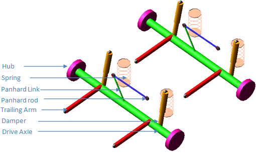
Description
The template is used in conjunction with the dual tire template in the tractor assembly as the driving solid axle. Longitudinal load is reacted by the rigid hockey sticks and lateral load is reacted by the panhard rod. Drive torque left and right are applied as rotational single component forces between hub parts and the solid axle. A simple model of a limited slip differential is also included in this suspension template. There are no rigid parts or gears in the axle differential unit: a differential torque is transferred from one hub to the other, depending on the difference of the wheel rotational speeds. The rotational speeds of the left and right half shafts are computed in a user defined solver variable and their difference is used as independent variable in the akima interpolation of the limited slip differential spline. An input communicator of type solver variable receives the total axle torque. That value, corrected with the appropriate differential torque, is then referenced in the two joint force actuators. The joint force actuators produce the driving torque between the rotating hub parts and the solid axle.
Files referenced
mdi_viscous.dif
mdi_0001.spr
mdi_0001.bus
mdi_0001.dpr
Topology
Hub parts are connected to the solid axle via rotational joints. Dual wheel template mounts to the hubs. Hockey sticks are connected to the solid axle via a combination of primitive joints and bushings. The suspension is connected to the tractor subsystem via mount parts at the springs, dampers, panhard rod bushings and hockey sticks revolute joints.
The following table maps the topology of the template:
The joint: | Connects the part: | To the part: |
|---|---|---|
jk[lr]con_lower_shock | ge[lr]_lower_shock | sw[lr]_lower_shock_mount |
jk[lr]con_lower_shock_2 | ge[lr]_lower_shock_2 | sw[lr]_lower_shock_mount_2 |
jk[lr]rev_trailing_arm_to_frame | g ge[lr]_trailing_arm | mt[lr]_trailing_arm_to_frame |
jk[lr]rev_trailing_arm_to_frame_2 | g ge[lr]_trailing_arm_2 | mt[lr]_trailing_arm_to_frame_2 |
jk[lr]sph_upper_shock | ge[lr]_upper_shock | mt[lr]_shock_to_frame |
jk[lr]sph_upper_shock_2 | ge[lr]_upper_shock_2 | mt[lr]_shock_to_frame_2 |
jkshoo_panhard_link_to_rod | ges_panhard_link | ges_panhard_rod |
jkshoo_panhard_link_to_rod_2 | ges_panhard_link_2 | ges_panhard_rod_2 |
jkssph_panhard_rod_to_frame | ges_panhard_rod | mts_panhard_rod_to_frame |
jkssph_panhard_rod_to_frame_2 | ges_panhard_rod_2 | mts_panhard_rod_to_frame_2 |
jo[lr]cyl_shock | ge[lr]_upper_shock | ge[lr]_lower_shock |
jo[lr]cyl_shock_2 | ge[lr]_upper_shock_2 | ge[lr]_lower_shock_2 |
jo[lr]fix_trailing_arm_to_axle | ge[lr]_trailing_arm | ge[lr]_drive_axle |
jo[lr]fix_trailing_arm_to_axle_2 | ge[lr]_trailing_arm_2 | ge[lr]_drive_axle_2 |
jo[lr]rev_hub_to_axle | ge[lr]_hub | ge[lr]_drive_axle |
jo[lr]rev_hub_to_axle_2 | ge[lr]_hub_2 | ge[lr]_drive_axle_2 |
josfix_axles | gel_drive_axle | ger_drive_axle |
josfix_axles_2 | gel_drive_axle_2 | ger_drive_axle_2 |
josfix_panhard_link_to_axle | ges_panhard_link | ger_drive_axle |
josfix_panhard_link_to_axle_2 | ges_panhard_link_2 | ger_drive_axle_2 |
jo[lr]per_tripot_to_hub | mt[lr]_tripot_to_differential | gel_hub |
jo[lr]per_tripot_to_hub_2 | mt[lr]_tripot_to_differential_2 | gel_hub_2 |
bk[lr]_lower_shock.field | sw[lr]_lower_shock_mount | ge[lr]_lower_shock |
bk[lr]_lower_shock.field_2 | sw[lr]_lower_shock_mount_2 | ge[lr]_lower_shock_2 |
bk[lr]_trailing_arm_to_frame.field | mt[lr]_trailing_arm_to_frame | ge[lr]_trailing_arm |
bk[lr]_trailing_arm_to_frame.field_2 | mt[lr]_trailing_arm_to_frame_2 | ge[lr]_trailing_arm_2 |
bk[lr]_upper_shock.field | mt[lr]_shock_to_frame | ge[lr]_upper_shock |
bk[lr]_upper_shock.field_2 | mt[lr]_shock_to_frame_2 | ge[lr]_upper_shock_2 |
bks_panhard_link_to_rod.field | ges_panhard_rod | ges_panhard_link |
bks_panhard_link_to_rod.field_2 | ges_panhard_rod_2 | ges_panhard_link_2 |
bks_panhard_rod_to_frame.field | mts_panhard_rod_to_frame | ges_panhard_rod |
bks_panhard_rod_to_frame.field_2 | mts_panhard_rod_to_frame_2 | ges_panhard_rod_2 |
da[lr]_damper.force | ge[lr]_lower_shock | ge[lr]_upper_shock |
da[lr]_damper.force_2 | ge[lr]_lower_shock_2 | ge[lr]_upper_shock_2 |
ns[lr]_spring.force | sw[lr]_lower_spring_mount | mt[lr]_spring_to_frame |
ns[lr]_spring.force_2 | sw[lr]_lower_spring_mount_2 | mt[lr]_spring_to_frame_2 |
ns[lr]_spring.spdp_force | sw[lr]_lower_spring_mount | mt[lr]_spring_to_frame |
ns[lr]_spring.spdp_force_2 | sw[lr]_lower_spring_mount_2 | mt[lr]_spring_to_frame_2 |
Hub Compliance on | ||
jo[lr]sph_hub_compliance | ge[lr]_hub | ge[lr]_drive_axle |
bg[lr]_hub_compliance | ge[lr]_hub | ge[lr]_drive_axle |
jo[lr]sph_hub_compliance_2 | ge[lr]_hub_2 | ge[lr]_drive_axle_2 |
bg[lr]_hub_compliance_2 | ge[lr]_hub_2 | ge[lr]_drive_axle_2 |
Hub Compliance off | ||
jo[lr]rev_hub_to_axle | ge[lr]_hub | ge[lr]_drive_axle |
jo[lr]rev_hub_to_axle_2 | ge[lr]_hub_2 | ge[lr]_drive_axle_2 |
Parameters
The following table lists the parameters in the template:
The parameter: | Takes the value: | Its units are: |
|---|---|---|
phs_driveline_active | integer | no units |
phs_kinematic_flag | integer | no units |
pvs_hub_compliance_active | integer | no units |
pvs_hub_compliance_2_active | integer | no units |
pv[lr]_camber_angle | real | angle |
pv[lr]_camber_angle_2 | real | angle |
pv[lr]_toe_angle | real | angle |
pv[lr]_toe_angle_2 | real | angle |
pvs_final_drive | real | no units |
pvs_final_drive_2 | real | no units |
pvs_hub_compliance_offset | real | length |
pvs_hub_compliance_2_offset | real | length |
Communicators
Mount parts provide connectivity between the template and the tractor, wheel subsystems. Input communicators receive information about the shock absorber, spring locations and so on. The output communicator provides information regarding the wheel, differential mounting and suspension parameter array and so on.
The following table lists the communicators in the template:
The communicator: | Belongs to the class: | Has the role: |
|---|---|---|
ci[lr]_shock_to_frame | mount | rear |
ci[lr]_shock_to_frame_2 | mount | rear_2 |
ci[lr]_spring_to_frame | mount | rear |
ci[lr]_spring_to_frame_2 | mount | rear_2 |
ci[lr]_tire_force | force | rear |
ci[lr]_tire_force_2 | force | rear_2 |
ci[lr]_trailing_arm_to_frame | mount | rear |
ci[lr]_trailing_arm_to_frame_2 | mount | rear_2 |
ci[lr]_tripot_to_differential | mount | rear |
ci[lr]_tripot_to_differential_2 | mount | rear_2 |
cis_panhard_rod_to_frame | mount | rear |
cis_panhard_rod_to_frame_2 | mount | rear_2 |
co[lr]_camber_angle | parameter_real | rear |
co[lr]_camber_angle_2 | parameter_real | rear_2 |
co[lr]_diff_tripot | location | rear |
co[lr]_diff_tripot_2 | location | rear_2 |
co[lr]_lddrv_outside_whl_mount | mount | rear |
co[lr]_lddrv_outside_whl_mount_2 | mount | rear_2 |
co[lr]_lddrv_suspension_mount | mount | rear |
co[lr]_lddrv_suspension_mount_2 | mount | rear_2 |
co[lr]_lddrv_suspension_upright | mount | rear |
co[lr]_lddrv_suspension_upright_2 | mount | rear_2 |
co[lr]_outside_wheel_center | location | rear |
co[lr]_outside_wheel_center_2 | location | rear_2 |
co[lr]_toe_angle | parameter_real | rear |
co[lr]_toe_angle_2 | parameter_real | rear_2 |
cos_axle_diff_mount | mount | rear |
cos_axle_diff_mount_2 | mount | rear_2 |
cos_driveline_active | parameter_integer | rear |
cos_driveline_active_2 | parameter_integer | rear_2 |
cos_halfshaft_omega_left | solver_variable | rear |
cos_halfshaft_omega_left_2 | solver_variable | rear_2 |
cos_halfshaft_omega_right | solver_variable | rear |
cos_halfshaft_omega_right_2 | solver_variable | rear_2 |
cos_suspension_parameters_ARRAY | array | rear |
cos_suspension_parameters_ARRAY_2 | array | rear_2 |
Note: | The integer parameter variables let you activate and deactivate the driveshafts and the Hub Compliance. The kinematic flag variable toggles between kinematic and compliant mode. |
msc_truck_trailer_axle
Overview
This template represents a solid axle suspension typically used on trailers.
Template name
_msc_truck_trailer_axle
Major role
Suspension
Application
Suspension and Full-vehicle analysis
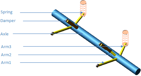
Description
The template represents a simple rigid axle trailing-arm suspension with springs and shock absorbers. Dual wheels are mounted on the axle to make the complete suspension system. It also connects to the brake templates.
Files referenced
msc_truck_trailer_axle_airbag.spr
msc_truck_trailer_axle.dpr
msc_truck_trailer_axle_shock.bus
msc_truck_trailer_A_frame.bus
msc_truck_trailer_arm_to_axle.bus
Topology
Hub parts are connected to the solid axle via rotational joints. Dual wheel template mounts to the hubs. The suspension is connected to the trailer subsystem via mount parts at the springs and dampers.
The following table maps the topology of the template:
The joint: | Connects the part: | To the part: |
|---|---|---|
jo[lr]cyl_shock | ge[lr]_shock_top | ge[lr]_shock_bottom |
bg[lr]_shock_to_frame_field | mt[lr]_shock_top | ge[lr]_shock_top |
bg[lr]_shock_to_trail_arm.field | ge[lr]_trail_arm | ge[lr]_shock_bottom |
bg[lr]_trail_arm_to_axle.field | ges_axle | ge[lr]_trail_arm |
da[lr]_damper.force | ge[lr]_shock_bottom | ge[lr]_shock_top |
bg[lr]_trail_arm_to_frame.field | mt[lr]_trail_arm_to_frame | ge[lr]_trail_arm |
ns[lr]_spring.force | ge[lr]_trail_arm | mt[lr]_airbag_to_frame |
ns[lr]_spring.spdp_force | ge[lr]_trail_arm | mt[lr]_airbag_to_frame |
Hub Compliance on | ||
jo[lr]sph_hub_compliance | ge[lr]_spindle | ge[lr]_axle |
bg[lr]_hub_compliance | ge[lr]_spindle | ge[lr]_axle |
Hub Compliance off | ||
jo[lr]rev_spindle | ge[lr]_spindle | ge[lr]_axle |
Parameters
The following table lists the parameters in the template:
The parameter: | Takes the value: | Its units are: |
|---|---|---|
pvs_hub_compliance_active | Integer | no units |
pv[lr]_camber_angle | Real | angle |
pv[lr]_toe_angle | Real | angle |
pvs_hub_compliance_offset | Real | length |
Communicators
Mount parts provide the connectivity to the trailer and wheel subsystems. Input communicators receive information about the toe and camber suspension orientation and the wheel-center location.
The following table lists the communicators in the template:
The communicator: | Belongs to the class: | Has the role: |
|---|---|---|
ci[lr]_airbag_to_frame | mount | real |
ci[lr]_shock_top | mount | inherit |
ci[lr]_trail_arm_to_frame | mount | inherit |
co[lr]_camber_angle | parameter_real | inherit |
co[lr]_pad_axle | mount | inherit |
co[lr]_pad_axle | mount | inherit |
co[lr]_toe_angle | parameter_real | inherit |
co[lr]_trl_outside_wheel_center | location | inherit |
co[lr]_trl_outside_whl_mount | mount | inherit |
co[lr]_trl_suspension_mnt | mount | inherit |
co[lr]_trl_suspension_upright | mount | inherit |
co[lr]_trl_wheel_center | location | inherit |
co[lr]_wheel_mount | mount | inherit |
cos_suspension_parameters_ARRAY | array | inherit |
Note: | The integer parameter variables let you activate and deactivate the Hub Compliance. |
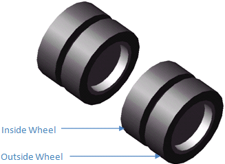
msc_truck_wheels_dual
Overview
The dual wheel template represents a dual wheel arrangement on drive and trailer axles of the truck. It uses the tire property file and supports three basic functions:
■Supports vertical load
■Develops longitudinal forces for acceleration and braking
■Develops lateral forces for cornering
Template name
_msc_truck_wheel_dual
Major role
Wheel
Application
Full-vehicle analyses
Description
The dual wheel system template consists of wheel parts rigidly connected to mount parts. The tire contact patch forces are transformed in forces and torques applied at the hub. A series of user-written subroutines perform the force calculation depending on the tire property file that you selected. The road property file determines the road contact model. For additional information about using tire and road models, see the Adams Tire online help.
Files referenced
The wheel system template references a tire property file for each wheel part. The default tire property file is msc_truck_fiala.tir, stored in the tires.tbl directory of the Adams Car Truck shared database.
Topology
The outside and inside wheel are rigidly connected by fixed joint, and the inside wheel in turn is connected to spindle.
Communicators
Mount parts provide connectivity to the suspension subsystems, and output communicators publish information about tire forces and wheel orientation. Tire force output communicator is used by the drive axle template in order to evaluate the halfshaft angular velocity during a quasi static analysis. The halfshaft velocity contributes to the calculation of the engine speed during quasi-static analysis.
The following table lists the communicators in the wheel system template.
The communicator: | Belongs to the class: | Has the role: |
|---|---|---|
ci[lr]_camber_angle | parameter_real | inherit |
ci[lr]_outside_wheel_center | location | inherit |
ci[lr]_suspension_upright | mount | inherit |
ci[lr]_suspension_mount | mount | inherit |
ci[lr]_toe_angle | parameter_real | inherit |
ci[lr]_wheel_center | location | inherit |
co[lr]_outside_tire_force | force | inherit |
co[lr]_rotor_to_wheel | mount | inherit |
co[lr]_tire_force | force | inherit |
co[lr]_wheel_orientation | orientation | inherit |
cos_tire_forces_array_left | array | inherit |
cos_tire_forces_array_right | array | inherit |
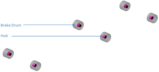
msc_truck_air_drum_brakes
Overview
The drum-brake system template represents an air brake device that applies resistance to the motion of a vehicle.
Template name
_msc_truck_air_drum_brakes
Major role
Brake_system
Application
Full-vehicle analysis to simulate the effect of braking on the dynamics of the vehicle
Description
The drum-brake system template represents a model of air brake system. It converts the brake line pressure to brake torque which is applied to the wheels. This template models the brakes at three axles.
Files referenced
None
Topology
An ac_point_torque_actuator acts between the suspension upright and wheel part. The brake line pressure is converted to brake_ torque based upon the friction coefficient and load sensitive pressure metering.
Parameters
The braking torque is expressed as a function of a number of parameters as listed below:
The parameter: | Takes the value: | Its units are: |
|---|---|---|
pvs_front_axle_load_at_max_braking | real | force |
pvs_drive_axle_load_at_max_braking | real | force |
pvs_brake_mu | real | no_units |
pvs_demand_to_pressure_cnvt | real | no_units |
pvs_drum_radius | real | length |
pvs_drum_width | real | length |
pvs_hub_wheel_offset | real | length |
pvs_pressure_to_torque_cnvt | real | torque |
Communicators
Mount parts provide connectivity between the template and suspension subsystems. Input communicators receive information about the toe and camber suspension orientation and the wheel-center location. Input to the brake system is brake demand.
The following table lists the communicators in the template:
The communicator: | Belongs to the class: | Has the role: |
|---|---|---|
ci[lr]_camber_angle | parameter_real | front |
ci[lr]_camber_angle_front_drive | parameter_real | rear |
ci[lr]_camber_angle_rear_drive | parameter_real | rear_2 |
ci[lr]_inside_tire_force_front_drive | force | rear |
ci[lr]_inside_tire_force_rear_drive | force | rear_2 |
ci[lr]_outside_tire_force_front_drive | force | rear |
ci[lr]_outside_tire_force_rear_drive | force | rear_2 |
ci[lr]_suspension_upright | mount | front |
ci[lr]_suspension_upright_front_drive | mount | rear |
ci[lr]_suspension_upright_rear_drive | mount | rear_2 |
ci[lr]_tire_force | force | front |
ci[lr]_toe_angle | parameter_real | front |
ci[lr]_toe_angle_front_drive | parameter_real | rear |
ci[lr]_toe_angle_rear_drive | parameter_real | rear_2 |
ci[lr]_wheel | mount | front |
ci[lr]_wheel_front_drive | mount | rear |
ci[lr]_wheel_rear_drive | mount | rear_2 |
ci[lr]_wheel_center | location | front |
ci[lr]_wheel_center_front_drive | location | rear |
ci[lr]_wheel_center_rear_drive | location | rear_2 |
cis_brake_demand | solver_variable | any |
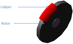
msc_truck_brake
Overview
The tractor disc-brake system template represents a device that applies resistance to the motion of a vehicle.
Template name
_msc_truck_tractor_brake
Major role
Brake_system
Application
Full-vehicle (tractor only) analysis to simulate the effect of braking on the dynamics of the vehicle.
Description
The disc-brake system template represents a simple model of a brake system. It applies a rotational torque between the caliper and the rotor. A pair of disc brakes is mounted on each axle. The brake line pressure is divided into two channels, front and rear, depending on the brake_bias. This brake line pressure is converted to brake torque depending upon the brake_demand, coefficient of friction, effective piston radius and the velocity of the vehicle.
Files referenced
None
Topology
The rotor is rigidly attached to the wheel. A caliper is fixed to the suspension, housing any number of pistons, the effective area of which is specified as a parameter. The brake bias determines the amount of braking line pressure distributed to each axle. Effective piston radius and the friction coefficient are used to convert the brake line pressure into braking torque. The disc-brake template is a simple model of a brake system. It does not model the complex interaction between the rotor and caliper.
Parameters
The following table lists the parameters in the template.
The parameter: | Takes the value: | Its units are: |
|---|---|---|
pvs_front_brake_bias | Real | No units |
pvs_front_brake_mu | Real | No units |
pvs_front_effective_piston_radius | Real | mm |
pvs_front_piston_area | Real | mm2 |
pvs_front_rotor_hub_wheel_offset | Real | mm |
pvs_front_rotor_hub_width | Real | mm |
pvs_front_rotor_width | Real | mm |
pvs_max_brake_value | Real | No units |
pvs_rear_brake_bias | Real | No units |
pvs_rear_brake_mu | Real | No units |
pvs_rear_effective_piston_radius | Real | mm |
pvs_rear_piston_area | Real | mm2 |
pvs_rear_rotor_hub_wheel_offset | Real | mm |
pvs_rear_rotor_hub_width | Real | mm |
pvs_rear_rotor_width | Real | mm |
Communicators
Mount parts provide the connectivity to the axle and wheels. Input communicators receive information about the toe and camber suspension orientation and the wheel-center location. Input to the brake system is brake demand.
The following table lists the communicators in the template.
The communicator: | Belongs to the class: | Has the role: |
|---|---|---|
ci[lr]_front_camber_angle | parameter_real | front |
ci[lr]_front_rotor_to_wheel | mount | front |
ci[lr]_front_tire_force | force | front |
ci[lr]_front_toe_angle | parameter_real | front |
ci[lr]_front_wheel_center | location | front |
ci[lr]_front_suspension_ upright | mount | front |
ci[lr]_rear_rotor_ro_wheel_1 | mount | rear |
ci[lr]_rear_rotor_ro_wheel_2 | mount | rear_2 |
ci[lr]_rear_suspension_ upright_1 | mount | rear |
ci[lr]_rear_suspension_ upright_2 | mount | rear_2 |
ci[lr]_rear_toe_angle | parameter_real | rear |
ci[lr]_rear_tire_force | force | rear |
ci[lr]_rear_camber_angle | parameter_real | rear |
ci[lr]_rear_wheel_center_1 | location | rear |
ci[lr]_rear_wheel_center_2 | location | rear_2 |
cis_brake_demand | solver_variable | any |
cos_max_brake_value | parameter_real | inherit |
msc_truck_trailer_brake
Overview
The trailer disc-brake system template represents a device that applies resistance to the motion of a vehicle.
Template name
_msc_truck_trailer_brake
Major role
Brake_system
Application
Full-vehicle (tractor and semi-trailer) analysis to simulate the effect of braking on the dynamics of the vehicle
Description
The disc-brake system template represents a simple model of a brake system. It applies a rotational torque between the caliper and the rotor. A pair of disc brake is mounted on each axle. The brake line pressure is divided into three channels, front, rear, and trailer depending upon the brake bias. This brake demand is converted to line pressure and brake torque depending upon the coefficient of friction, effective piston radius and the velocity of the vehicle.
Files referenced
None
Topology
Topology is same as _msc_truck_brake.
Parameters
The following table lists the parameters in the template.
The parameter: | Takes the value: | Its units are: |
|---|---|---|
pvs_front_brake_bias | real | No units |
pvs_front_brake_mu | real | No units |
pvs_front_effective_piston_radius | real | mm |
pvs_front_piston_area | real | mm2 |
pvs_front_rotor_hub_wheel_offset | real | mm |
pvs_front_rotor_hub_width | real | mm |
pvs_front_rotor_width | real | mm |
pvs_max_brake_value | real | No units |
pvs_rear_brake_bias | real | No units |
pvs_rear_brake_mu | real | No units |
pvs_rear_effective_piston_radius | real | mm |
pvs_rear_piston_area | real | mm2 |
pvs_rear_rotor_hub_wheel_offset | real | mm |
pvs_rear_rotor_hub_width | real | mm |
pvs_rear_rotor_width | real | mm |
pvs_trailer_brake_bias | real | No units |
pvs_trailer_brake_mu | real | No units |
pvs_trailer_effective_piston_radius | real | mm |
pvs_trailer_piston_area | real | mm2 |
pvs_trailer_rotor_hub_wheel_offset | real | mm |
pvs_trailer_brake_bias | real | no units |
pvs_trailer_rotor_hub_width | real | mm |
pvs_trailer_rotor_width | real | mm |
Communicators
Mount parts provide the connectivity between the template and axle, wheel subsystems. Input communicators receive information about the toe and camber suspension orientation and the wheel-center location. Input to the brake system is brake demand.
The following table lists the communicators in the template.
The communicator: | Belongs to the class: | Has the role: |
|---|---|---|
ci[lr]_front_camber_angle | parameter_real | front |
ci[lr]_front_rotor_to_wheel | mount | front |
ci[lr]_front_tire_force | force | front |
ci[lr]_front_toe_angle | parameter_real | front |
ci[lr]_front_wheel_center | location | front |
ci[lr]_front_suspension_ upright | mount | front |
ci[lr]_rear_rotor_ro_wheel_1 | mount | rear |
ci[lr]_rear_rotor_ro_wheel_2 | mount | rear_2 |
ci[lr]_rear_suspension_ upright_1 | mount | rear |
ci[lr]_rear_suspension_ upright_2 | mount | rear_2 |
ci[lr]_rear_toe_angle | parameter_real | rear |
ci[lr]_rear_tire_force | force | rear |
ci[lr]_rear_camber_angle | parameter_real | rear |
ci[lr]_rear_wheel_center_1 | location | rear |
ci[lr]_rear_wheel_center_2 | location | rear_2 |
ci[lr]_trailer_camber_angle | parameter_real | trailer |
ci[lr]_trailer_rotor_to_wheel_1 | mount | trailer |
ci[lr]_trailer_rotor_to_wheel_2 | mount | trailer_2 |
ci[lr]_trailer_suspension_upright_1 | mount | trailer |
ci[lr]_trailer_suspension_upright_2 | mount | trailer_2 |
ci[lr]_trailer_wheel_center_1 | location | trailer |
ci[lr]_trailer_wheel_center_2 | location | trailer_2 |
ci[lr]_trailer_toe_angle | parameter_real | trailer |
cis_brake_demand | solver_variable | any |
cos_max_brake_value | parameter_real | inherit |
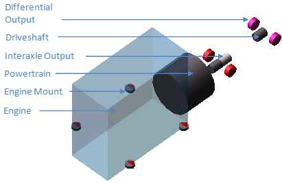
msc_truck_powertrain
Overview
This template represents the powertrain including the clutch and gear box.
Template name
_msc_truck_powertrain
Major role
powertrain
Application
Full-vehicle analysis
Description
The powertrain template is functional representation based on an internal combustion engine, clutch and a gearbox model. The engine combustion model takes the throttle demand and produces a crankshaft torque as a result of a three dimensional spline interpolation. Independent variables are engine RPM and throttle position. Torque is divided with inter- and intra-axle differentials.
Files referenced
mdi_0001.bus
V12_engine_map.pwr
MDI_viscous.dif
Topology
The powertrain produces a transmission output torque acting on the front driveshaft, reacted on the powertrain part. The front driveshaft drives a coupler splitting torque between the front and rear axles. The front and rear axles then split torque left and right through differentials.
The following table maps the topology of the template.
The joint: | Connects the part: | To the part: |
|---|---|---|
jo[lr]rev_diff_output_F | ge[lr]_diff_output_F | mts_diff_mount_F |
jo[lr]rev_diff_output_R | ge[lr]_diff_output_R | mts_diff_mount_R |
josrev_front_driveshaft_to_axle | ges_front_driveshaft | mts_diff_mount_F |
josrev_interaxle_diff_output_to_axle | ges_interaxle_diff_output | mts_diff_mount_F |
josrev_rear_driveshaft_to_axle | ges_rear_driveshaft | mts_diff_mount_R |
grsdif_front_drive_axle | josrev_interaxle_diff_output_to_axle | jolrev_diff_output_F jorrev_diff_output_F |
grsdif_interaxle_diff | josrev_front_driveshaft_to_axle | josrev_interaxle_diff_output_to_axle josrev_rear_driveshaft_to_axle |
grsdif_rear_drive_axle | josrev_rear_driveshaft_to_axle | jolrev_diff_output_R jorrev_diff_output_R |
bkl_front_engine_mount.field | mts_powertrain_to_body | ges_powertrain |
bkl_rear_engine_mount.field | mts_powertrain_to_body | ges_powertrain |
bkr_front_engine_mount.field | mts_powertrain_to_body | ges_powertrain |
bkr_rear_engine_mount.field | mts_powertrain_to_body | ges_powertrain |
Parameters
The following table lists the parameters used in the template:
The parameter: | Takes the value: | Its units are: |
|---|---|---|
pvs_clutch_capacity | Real | troque |
pvs_clutch_close | Real | no units |
pvs_clutch_damping | Real | torsion_damping |
pvs_clutch_open | Real | no units |
pvs_clutch_stiffness | Real | none |
pvs_clutch_tau | Real | time |
pvs_ems_gain | Real | none |
pvs_ems_max_throttle | Real | no units |
pvs_ems_throttle_off | Real | no units |
pvs_engine_idle_speed | Real | no units |
pvs_engine_inertia | Real | inertia |
pvs_engine_rev_limit | Real | no units |
pvs_final_drive | Real | no units |
pvs_gear_1 … to … 18 | Real | no units |
pvs_gear_r | Real | no units |
pvs_graphics_flag | Integer | no units |
pvs_max_gears | Integer | no units |
pvs_max_throttle | Real | no units |
Communicators
The following table lists the communicators in the template:
The communicator: | Belongs to the class: | Has the role: |
|---|---|---|
ci[lr]_diff_tripot_F | location | rear |
ci[lr]_diff_tripot_R | location | rear_2 |
ci[lr]_tire_force_F | force | rear |
ci[lr]_tire_force_R | force | rear_2 |
cis_clutch_demand | solver_variable | inherit |
cis_diff_mount_F | mount | rear |
cis_diff_mount_R | mount | rear_2 |
cis_initial_engine_rpm | parameter_real | any |
cis_powertrain_to_body | mount | inherit |
cis_sse_diff1 | diff | inherit |
cis_throttle_demand | solver_variable | inherit |
cis_transmission_demand | solver_variable | inherit |
co[lr]_tripot_to_differential_F | mount | rear |
co[lr]_tripot_to_differential_R | mount | rear_2 |
cos_clutch_displacement_ic | solver_variable | inherit |
cos_default_downshift_rpm | parameter_real | inherit |
cos_default_upshift_rpm | parameter_real | inherit |
cos_diff_ratio | parameter_real | inherit |
cos_engine_idle_rpm | parameter_real | inherit |
cos_engine_map | spline | inherit |
cos_engine_max_rpm | parameter_real | inherit |
cos_engine_rpm | solver_variable | inherit |
cos_engine_speed | solver_variable | rear_2 |
cos_max_engine_braking_torque | solver_variable | inherit |
cos_max_engine_driving_torque | solver_variable | inherit |
cos_max_gears | parameter_integer | inherit |
cos_max_throttle | parameter_real | inherit |
cos_powertrain_gse | general_state_equation | inherit |
cos_transmission_input_omega | solver_variable | inherit |
cos_transmission_spline | spline | inherit |
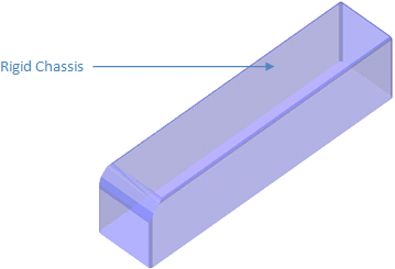
msc_bus_rigid_chassis
Overview
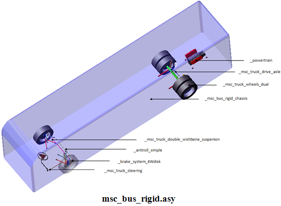
This template represents the chassis frame to which other subassemblies are attached.
Template name
_msc_bus_rigid_chassis
Major role
Body
Application
Full-vehicle analysis
Description
The template represents the chassis frame to which other subassemblies like suspension, steering and powertrain etc. are attached. The frontal area and aero drag coefficient parameters are used to calculate the aerodynamic drag.
Files referenced
none
Topology
Aero forces are applied to ges_frame.
Parameters
The following table lists the parameters used in the template:
The parameter: | Takes the value: | Its units are: |
|---|---|---|
pvs_aero_frontal_area | real | area |
pvs_air_density | real | density |
pvs_body_height | real | length |
pvs_body_length | real | length |
pvs_body_width | real | length |
pvs_drag_coefficient | real | no units |
Communicators
Mount parts provide the connectivity between the template and suspension, powertrain, and wheel subsystems etc. Input communicators receive information about the tire reference locations.
The following table lists the communicators in the template:
The communicator: | Belongs to the class: | Has the role: |
|---|---|---|
cis_std_tire_ref | location | inherit |
co[lr]_front_susp_to_body | mount | front |
co[lr]_suspension_to_frame_rear | mount | rear |
co[lr]_suspension_to_frame_rear_2 | mount | rear_2 |
cos_aero_drag_force | solver_varible | inherit |
cos_aero_frontal_area | parameter_real | inherit |
cos_air_density | parameter_real | inherit |
cos_body_subsystem | mount | inherit |
cos_chassis_path_reference | marker | inherit |
cos_drag_coefficient | parameter_real | inherit |
cos_driver_reference | marker | inherit |
cos_fd_panhard_rod_to_frame | mount | rear |
cos_lateral_rod_to_frame | mount | any |
cos_lower_bump_stop_to_frame | mount | inherit |
cos_measure_for_distance | mount | inherit |
cos_pitman_mount | mount | inherit |
cos_powertrain_to_body | mount | any |
cos_press_valve_link_to_frame | mount | inherit |
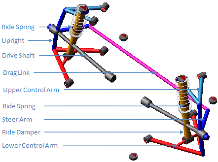
msc_truck_double_wishbone_suspension
Overview
This template represents the double wishbone (upper-lower A arm) suspension system.
Template name
_msc_truck_double_wishbone_suspension
Major role
Suspension
Application
suspension analysis.
Description
The template represents the double-wishbone (also known as double A arm) independent suspension system.
Files referenced
mdi_0004.bus
mdi_0001.bus
mdi_shk_0001.dpr
mdi_0001.bum
mdi_0001.spr
Topology
The following table maps the topology of the template.
The joint: | Connects the part: | To the part |
|---|---|---|
jk[lr]hoo_lwr_strut_kinematic | ge[lr]_lower_strut | ge[lr]_lower_control_arm |
jk[lr]hoo_top_mount_kinematic | ge[lr]_upper_strut | mt[lr]_strut_to_body |
jk[lr]rev_lca | ge[lr]_lower_control_arm | ges_subframe |
jk[lr]rev_uca | ge[lr]_upper_control_arm | mt[lr]_uca_to_body |
jo[lr]con_drive_sft_int_jt | ge[lr]_tripot | ge[lr]_drive_shaft |
jo[lr]con_drive_sft_otr | ge[lr]_drive_shaft | ge[lr]_spindle |
jo[lr]cyl_lwr_upr_strut | ge[lr]_lower_strut | ge[lr]_upper_strut |
jo[lr]sph_lca_balljoint | ge[lr]_upright | ge[lr]_lower_control_arm |
jo[lr]sph_uca_balljoint | ge[lr]_upper_control_arm | ge[lr]_upright |
jo[lr]tra_tripot_to_differential | ge[lr]_tripot | mt[lr]_tripot_to_differential |
joscon_left_upright_to_draglink | ge[lr]_upright | ge[lr]_draglink |
josfix_subframe_rigid | ges_subframe | mts_subframe_to_body |
jossph_right_upright_to_draglink | ger_upright | ges_draglink |
bg[lr]_subframe_front.field | mts_subframe_to_body | ges_subframe |
bg[lr]_subframe_rear.field | mts_subframe_to_body | ges_subframe |
bk[lr]_lca_front.field | ges_subframe | ge[lr]_lower_control_arm |
bk[lr]_lca_rear.field | ges_subframe | ge[lr]_lower_control_arm |
bk[lr]_lwr_strut.field | ge[lr]_lower_control_arm | ge[lr]_lower_strut |
bk[lr]_top_mount.field | mt[lr]_strut_to_body | ge[lr]_upper_strut |
bk[lr]_uca_front.field | mt[lr]_uca_to_body | ge[lr]_upper_control_arm |
bk[lr]_uca_rear.field | mt[lr]_uca_to_body | ge[lr]_upper_control_arm |
bu[lr]_jounce_stop.force | ge[lr]_lower_strut | ge[lr]_upper_strut |
da[lr]_ride_damper.force | ge[lr]_lower_strut | ge[lr]_upper_strut |
ns[lr]_ride_spring.force | ge[lr]_lower_strut | mt[lr]_strut_to_body |
ns[lr]_ride_spring.spdp_force | ge[lr]_lower_strut | mt[lr]_strut_to_body |
Hub Compliance on | ||
jo[lr]sph_hub_compliance | ge[lr]_spindle | ge[lr]_upright |
bg[lr]_hub_compliance | ge[lr]_spindle | ge[lr]_upright |
Hub Compliance off | ||
jo[lr]rev_spindle_upright | ge[lr]_spindle | ge[lr]_upright |
Parameters
The following table lists the parameters in the template.
The parameter: | Takes the value: | Its units are: |
|---|---|---|
pv[lr]_camber_angle | real | angle |
pv[lr]_drive_shaft_offset | real | length |
pv[lr]_toe_angle | real | angle |
pvs_hub_compliance_offset | real | length |
phs_driveline_active | integer | no units |
phs_kinematic_flag | integer | no units |
pvs_subframe_active | integer | no units |
pvs_hub_compliance_active | integer | no units |
Communicators
Mount parts provide the connectivity between the template and suspension mounts on chassis. Output communicator provide toe-camber angle and tire location information.
The following table lists the communicators in the template.
The communicator: | Belongs to the class: | Has the role: |
|---|---|---|
ci[lr]_ARB_pickup | location | inherit |
ci[lr]_strut_to_body | mount | inherit |
ci[lr]_tripot_to_differential | mount | inherit |
ci[lr]_uca_to_body | mount | inherit |
cis_subframe_to_body | mount | inherit |
co[lr]_arb_bushing_mount | mount | inherit |
co[lr]_camber_angle | mount | inherit |
co[lr]_droplink_to_suspension | mount | inherit |
co[lr]_suspension_mount | mount | inherit |
co[lr]_suspension_upright | mount | inherit |
co[lr]_toe_angle | parameter_real | inherit |
co[lr]_tripot_to_differential | location | inherit |
co[lr]_wheel_center | location | inherit |
cos_driveline_active | parameter_integer | inherit |
cos_engine_to_subframe | mount | inherit |
cos_rack_housing_to_suspension_subframe | mount | inherit |
cos_strarm_to_spindle | mount | front |
cos_suspension_parameters_ARRAY | array | inherit |
Note: | The integer parameter variables let you activate and deactivate the driveshafts and the Hub Compliance. The kinematic flag variable toggles between kinematic and compliant mode. |
The following figures show the location of the templates in the assembly