Working with the TASA Test Rig
TASA stands for Tandem Axle Suspension Analysis. Adams Car Truck uses the new test rig, named __MDI_TASA_TESTRIG, in all suspension analyses of tandem (twin) axle suspension systems. When you create a suspension assembly, Adams Car Truck assembles the TASA test rig with the selected suspension and steering subsystems.
This test rig is based on __MDI_SUSPENSION_TESTRIG which is used for suspension analysis of single axles. The new __MDI_TASA_TESTRIG includes an additional set of jacks to actuate aft axle.
Learn about the suspension test rig:
Benefits of Using the TASA Test Rig
Adams Car Truck provides off-the-shelf access to a new test rig named __MDI_TASA_TESTRIG, which is an extended version of __MDI_SUSPENSION_TESTRIG, to support analysis of tandem axles. It therefore eliminates the need to spend the effort creating and maintaining a custom test rig, events and output to perform analyses on suspensions that have multiple (that is, "tandem") axles.
You can use the TASA test rig to:
Do suspension analysis of tandem axle suspension systems.
■Perform Pitch Wheel Travel and Articulation Wheel Travel analyses.
■Perform kinematic and compliance analysis of tandem axle suspension systems.
■Include dual wheels as needed.
■Study the effect of load transfer due to equalizer.
Learn about the benefits of using the standard suspension test rig:
Communicators in the TASA Test Rig
The following tables describe the input and output communicators in the TASA test rig (__MDI_TASA_TESTRIG). In the tables, the notation:
■[lr] indicates that there is both a left and right communicator of the specified name, as in ci[lr]_camber_angle.
■s indicates a single communicator, as in cis_steering_rack_joint.
Input Communicators in TASA Test Rig
The communicator: | Belongs to the class: | From minor role: | Receives: |
|---|---|---|---|
ci[lr]_camber_angle | parameter_real | rear | Camber angle value from the fore suspension subsystem. Sets the correct orientation of the test rig wheels. |
ci[lr]_camber_angle_aft | parameter_real | rear_2 | Camber angle value from the aft suspension subsystem. Sets the correct orientation of the test rig wheels. |
ci[lr]_diff_tripot | location | rear | Location of the fore differential. |
ci[lr]_diff_tripot_aft | location | rear_2 | Location of the aft differential. |
ci[lr]_toe_angle | parameter_real | rear | Toe angle value from the fore suspension subsystem. Sets the correct orientation of the test rig wheels. |
ci[lr]_toe_angle_aft | parameter_real | rear_2 | Toe angle value from the aft suspension subsystem. Sets the correct orientation of the test rig wheels. |
ci[lr]_suspension_mount | mount | rear | Fore subsystem part to which the test rig wheels can attach. |
ci[lr]_suspension_mount_aft | mount | rear_2 | Aft subsystem part to which the test rig wheels can attach. |
ci[lr]_suspension_upright | mount | rear | Fore subsystem upright part from suspension subsystem. |
ci[lr]_suspension_upright_aft | mount | rear_2 | Aft subsystem upright part from suspension subsystem. |
ci[lr]_jack_frame | mount | rear | Not matched (fixed to ground). |
ci[lr]_jack_frame_aft | mount | rear_2 | Not matched (fixed to ground). |
ci[lr]_wheel_center | location | rear | Location of the wheel center from the fore suspension subsystem. Test rig wheels attach to the suspension at that location. |
ci[lr]_wheel_center_aft | location | rear_2 | Location of the wheel center from the aft suspension subsystem. Test rig wheels attach to the suspension at that location. |
cis_driveline_active | parameter_integer | rear | Integer value stored in the fore suspension template/subsystem that indicates the activity of the drivetrain. |
cis_driveline_active_aft | parameter_integer | rear_2 | Integer value stored in the aft suspension template/subsystem that indicates the activity of the drivetrain. |
cis_powertrain_to_body | mount | any | Part to which differential outputs are constrained. |
cis_steering_rack_joint | joint_for_motion | any | Steering-rack translational joint from the steering subsystem. |
cis_steering_wheel_joint | joint_for_motion | any | Steering-wheel revolute joint from the steering subsystem. |
cis_suspension_parameters_ARRAY | array | rear | Array used in the fore suspension characteristic calculations; comes from the fore suspension subsystems. |
cis_suspension_parameters_ARRAY_aft | array | rear_2 | Array used in the aft suspension characteristic calculations; comes from the aft suspension subsystems. |
cos_leaf_adjustment_multiplier | array | rear | For Leaf Spring toolkit. It is currently not supported in the standard product. |
cos_leaf_adjustment_multiplier_aft | array | rear_2 | For Leaf Spring toolkit. It is currently not supported in the standard product. |
cos_characteristics_input_ARRAY | array | rear | Suspension, vehicle, and test-rig parameters array IDs used by fore template/subsystem suspension characteristics calculations routines. |
cos_characteristics_input_ARRAY_aft | array | rear_2 | Suspension, vehicle, and test-rig parameters array IDs used by aft template/subsystem suspension characteristics calculations routines. |
co[l,r]_tripot_to_differential | mount | rear | Outputs the ge[lr]_diff_output parts. |
co[l,r]_tripot_to_differential_aft | mount | rear_2 | Outputs the ge[lr]_diff_output_aft parts. |
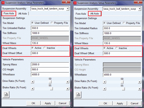
About Dual Wheels:
The __MDI_TASA_TESTRIG (__MDI_SUSPENSION_TESTRIG) test rig allows you to model dual tires (wheels) in your suspension assembly.
You can activate or deactivate dual wheels through Set Suspension Parameters dialog box from Simulate > Suspension Analysis> Set Suspension Parameters.
You can set dual wheels for each axle by activating or deactivating it on "Fore Axle" and "Aft Axle" tab.
The "Dual Wheel Offset" field is used to specify the lateral offset for the placement of the outside wheel from inside wheel center. The mass, inertia and tire properties (that is, tire radius, stiffness and so on.) of the inside wheel part (tire) will be set to the outside wheel part (tire).
When dual wheels are active, tire forces (reactions) gets distributed on inside and outside wheels.
Creating Assemblies with __MDI_TASA_TESTRIG
Two methods are available for creating a TASA assembly:
Using two subsystems.
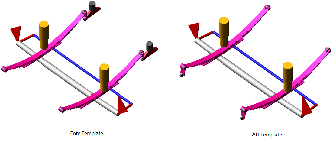
You can create a TASA assembly using two subsystems, one for fore axle and one for aft axle.
To create a TASA assembly:
1. Create template(s) for fore and aft axles.
2. Perform communicator testing between the suspension template(s) and __MDI_TASA_TESTRIG.
3. Create subsystems for fore and aft axle with different minor roles (for example, rear and rear_2).
4. In the Standard Interface, from the File menu, point to New, and then select Suspension Assembly…
5. Press F1 and then follow the instructions in the dialog box help for New Suspension Assembly.
6. Select "__MDI_TASA_TESTRIG" in Suspension Test Rig option menu.
7. Select or browse subsystem for fore axle in "Suspension Subsystem 1" field.
8. After selecting __MDI_TASA_TESTRIG you will see toggle button of "Suspension Subsystem 2".
9. Select toggle button of "Suspension Subsystem 2", it will activate field, select or browse subsystem for aft axle.
10. Select OK.
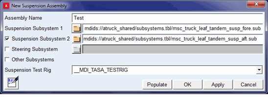
The "Suspension Subsystem 2" is an optional field as it isn't required for single subsystem method (see below).
The fore subsystem should be created with minor role as "rear" and aft subsystem should be created with minor role as "rear_2". This method is recommended for creating TASA assembly.
Using single subsystem
You can create single template in which both axles (fore and aft suspension) are modeled in a template.
The sample template msc_truck_tandem_drive_axle.tpl is available in atruck_shared database.
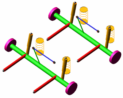
This template represents the solid twin axle suspension in which both axles are modelled in a template. The subsystem can be created using such template, and TASA assembly can be created using single suspension subsystem.
To create a TASA assembly:
1. Create a single template for both fore and aft axles.
2. Perform communicator testing between the template and __MDI_TASA_TESTRIG.
3. Create a subsystem using the template.
4. In the Standard Interface, from the File menu, point to New, and then select Suspension Assembly…
5. Press F1 and then follow the instructions in the dialog box help for New Suspension Assembly.
6. Select "__MDI_TASA_TESTRIG" in Suspension Test Rig option menu.
7. Select or browse subsystem in "Suspension Subsystem 1" field.
8. Select OK.
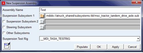
The "Suspension Subsystem 2" is an optional field as it is only required for the two subsystems method.
The __MDI_TASA_TESTRIG has two minor roles "rear and "rear_2", so you need to give attention to the communicators' minor roles defined in the template for proper communication with the test rig. For example, in the template msc_truck_tandem_drive_axle.tpl you can see two output communicators for toe_angle, one defined with minor_role as "rear" and the other defined with minor_role as "rear_2".
Examples of both methods are available in atruck_shared database as shown below:
Method | Using two subsystems | Using single subsystems |
|---|---|---|
Assembly | tasa_truck_leaf_tandem_susp.asy | tasa_msc_tractor_tandem_drive_axle.asy |
Subsystems | msc_truck_leaf_tandem_susp_fore.sub msc_truck_leaf_tandem_susp_aft.sub | msc_tractor_tandem_drive_axle.sub |
Templates | msc_truck_leaf_tandem_susp_fore.tpl msc_truck_leaf_tandem_susp_aft.tpl | msc_truck_tandem_drive_axle.tpl |