Reverting to Rigid from Flexible and Back Again
Switching from Rigid to Flex can be either by creating new flexible body using ViewFlex or importing a flexible body to replace a rigid body. You may want to go through the tutorial, Exchanging a Rigid Body with a Flexible Body, or Getting Started Using Adams Flex, as these resources will guide you through the steps of substituting a rigid body with a flexible body.
This section describes reverting back to the original rigid body and, subsequently from there, choosing to use the most recently used flexible body.
Overview of Replacing Rigid and Flexible Bodies
About Reverting to Rigid from Flexible Bodies
A rigid body is replaced by flexible body in following ways  :
:
:■The rigid body can be substituted with existing flexible body. When replacing rigid bodies, the replacement flexible bodies can either be an existing flexible body or a Modal Neutral File (MNF), MD DB or BDF file. When replacing flexible bodies, the replacement flexible bodies must be specified as an MNF or MD DB.
■The rigid body can be replaced by creating corresponding MNF file using ViewFlex option.
The Rigid to Flex swapping process identifies the connections on the existing body to other objects in the model, such as motions, forces, and joints. All markers are copied to the replacement flexible body even if the markers have no connections. This is because you may have user-written subroutines or Measures that reference the markers. The original rigid body is deactivated and hidden. Note that if a marker on the rigid body has a node-id which is not present on flexible body, then the marker is not copied to flexible body. A marker with a valid node-id has its motion associated to the corresponding node on flexible body. Thus, the locations of markers on flexible bodies may differ from those on rigid body. Motion, constraints and forces are transferred to the flexible body and its reference markers refer to flexible bodies as either the action or reaction body.
There are two ways go to a rigid body representation from a flexible body:
Note: | Adams Flex only transfers markers and any connections they define to the rigid body. It does not transfer string variables and other children of the flexible body. |
Make Rigid – Retain Mesh
This process does not reinstate the rigid part in place. The flexible body’s inertial modeling is set to ‘rigid coupling’ by the command:
‘part modify flexible_body name flexible_body_name=flex_body_1 invariants=yes,yes,no,no,no,no,yes,no,no’
It disables invariant 6, and the flexible body is considered rigid by ignoring all active modes.
Note: | Adams Flex only transfers markers and any connections they define to the rigid body. It does not transfer string variables and other children of the flexible body. |
Make Rigid – Original Geometry
After swapping the original rigid body with a flexible body, the user may have modified the flexible body marker locations and the flexible body may have differing mass properties than the original rigid part. It’s also possible that a few markers may have snapped their locations to their respective nodes on the flexible body. Hence, while reverting to the rigid part, the user has the option to use mass and marker locations from either the rigid or flexible bodies.
Mass and locale option
The following dialog helps users choose which mass and marker locations to use:
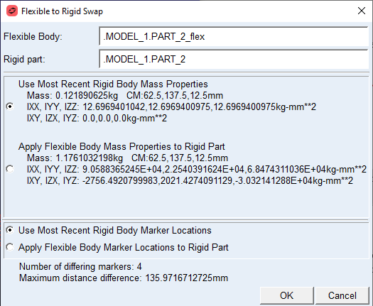
■Note that flexible body inertia properties are calculated with reference to the rigid body’s center_of_mass_marker or inertia marker, whichever is available.
■The above dialog box also shows the number of markers which have location differences. Maximum distance refers to the distance measured between two corresponding markers on rigid and flexible bodies.
■Note that node interface markers are not transferred to rigid body. (Typically node interface markers are identified by the naming convention ‘INT_NODE*’)
About Reverting to Flexible from Rigid Bodies
This section describes the reverting back to flexible body modeling after the rigid body has been recovered by either of the two above mentioned methods, namely, 1. Make Rigid (Retain Mesh) and 2. Make Rigid (Original Geometry)
Learn about:
Make Flexible (Import)
User can replace rigid body with a flexible body by importing MNF, MD-DB or BDF files. You may refer to section Replacing Existing Bodies with Flexible Bodies. If the rigid body has associated flexible body (by previous import and subsequent MakeRigid(Original Geometry) option), then previous import history will be overwritten with newly imported MNF.
Make Flexible (ViewFlex)
User can replace rigid body with flexible body by creating new flexible body using ViewFlex. For more details, you may refer to section Replacing Existing Bodies with Flexible Bodies.
Make Flexible (Use Previous)
If the rigid body had been reverted to by the option Make-Rigid (Original Geometry), then user can go back to the previous flexible body state again. Ideally, the user can keep switching between rigid and flexible body modeling via the options [Make Rigid (Original Geometry) ← → Make Flexible (Use Previous)]
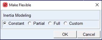
If the rigid body had been created using the option Make-Rigid (Retain Mesh), then the user is presented with following options of inertia modeling to make it flexible again: