Replacing Existing Bodies with Flexible Bodies
It is easy to replace a rigid body with a flexible body to more realistically model your mechanism. Because it is easy to replace rigid bodies with other flexible bodies, you can start gradually and slowly add complexity to your model as you need it. You may want to go through the tutorial, Exchanging a Rigid Body with a Flexible Body, or Getting Started Using Adams Flex, to step through the process of replacing a rigid body with a flexible body.
In addition to replacing a rigid body with a flexible body, you can replace an existing flexible body with a new flexible body. This may be useful if you want to modify the design of your flexible component.
Learn more about replacing rigid and flexible bodies:
Overview of Replacing Rigid and Flexible Bodies
Detailed Procedures
About Replacing Bodies with Flexible Bodies
To replace a rigid or flexible body with a flexible body, you start by specifying:
■The rigid or flexible body to be substituted and then the replacement flexible body. When replacing rigid bodies, the replacement flexible bodies can either be an existing flexible body or a Modal Neutral File (MNF) or MD DB. When replacing flexible bodies, the replacement flexible bodies must be specified as an MNF or MD DB.
■The position and orientation of the new flexible body. You specify the position and orientation of the replacement flexible body using one of three convenient alignment tools.
Adams Flex then identifies the connections on the existing body to other objects in the model, such as motions, forces, and joints. It displays the markers on the existing body through which the connections are made. Because the connections to flexible bodies are through markers, you will transfer the markers to the flexible body, thereby transferring the connections.
■If the existing body is a rigid body, Adams Flex searches for the markers on the rigid body, and transfers these markers to the nodes on the replacement flexible body that are closest to the markers. If a marker is used to define joints or forces, Adams Flex searches for interface nodes. For all other markers, it searches the entire set of nodes.
■If the existing body is another flexible body, the markers are already attached to nodes. Therefore, Adams Flex searches for the node closest to the attached node on the existing body. If the marker is attached to multiple nodes, Adams Flex searches for the closest node for each connection. Again, if a marker is used to define joints or forces, Adams Flex searches for interface nodes.
Adams Flex displays a Marker and Node Table to let you make any changes, such as change the node to which a marker will be moved.
Adams Flex moves all markers to the replacement flexible body even if the markers have no connections. This is because you may have User-written subroutines or Measures that reference the markers. By transferring all markers to flexible bodies, you ensure that all your subroutines and measures work. You can delete the markers if you want.
Because Adams Flex moves all markers, it also moves the center of mass (CM) marker. Once the marker is on the flexible body, however, it no longer indicates the CM nor does it stay coincident with the CM during a simulation. To eliminate confusion, Adams Flex renames the CM marker from the substituted rigid body to original_rigid_cm.
Note: | Adams Flex only transfers markers and any connections they define to the flexible body. It does not transfer string variables and other children of the rigid body. |
Overall Procedure for Replacing Rigid Bodies with Flexible Bodies
To replace a rigid body with a flexible body, perform the following steps:
Each step is briefly outlined below with links to more complete procedures.
Selecting the Bodies to be Replaced
You can replace a rigid body with a flexible body that is already in your model or you can specify an MNF or MD DB and Adams Flex creates a new flexible body. The following explains how to specify a flexible body already in your model. Learn more about selecting the body to be replaced.
To select the bodies:
1. On the screen, select the rigid body to be replaced.
2. Click the Bodies tab. From the Flexible Bodies container, select Rigid to Flex .
.
.(Classic Interface) From the Build menu, point to Flexible Bodies, and then select Rigid to Flex.
3. Under the Alignment tab, select Flex Body, and then select a flexible body that has already been imported into your model.
Position and Orient Replacement Body
You use the positioning options in the Alignment tab of the Swap rigid/flexible body dialog box to move the flexible body so that it is aligned with the existing body that it is replacing. Three alignment tools are available:
You can use one or more of the tools to position and orient the flexible body consistently with the rigid body. Once you've used these tools, you can use the Flip about buttons to rotate the body 180° into position.
Transferring the Connections
You use the Connections tab on the Swap rigid body dialog box to display and transfer the connections on the rigid body to the replacement flexible body. The Connections tab displays a Marker and Node table listing the connections and how they will be transferred. It also provides options for positioning the markers relative to the attachment nodes on the replacement flexible body. You can also launch a Node Finder Dialog Box to search for a different node.
To transfer the connections:
1. Review the list of marker connections and how Adams Flex will transfer them to the flexible body.
2. To change the node to which the marker will be transferred, enter the new node ID in the Node ID text box, and then select Apply. Learn more.
Use environment variable MSC_AVIEW_ERROR_ON_MISSING_NODE_ID = yes to abort the swap procedure if the rigid body marker has a node id bigger than the node count of the flexible body selected. Otherwise, the swap procedure is continued by assigning nearest node id to the marker.
3. If the attachment nodes are offset from the marker locations, you have three options:
■Do nothing, and simply select OK as explained in the next procedure. In which case, the Adams Solver (C++) creates a marker with an offset, while Adams Solver (FORTRAN) automatically introduces a massless part and fixed joint pair. You are not responsible for creating dummy parts.
■Move the marker to node location. Learn about this method.
■Maintain any parameterization that was set up through Adams View. Learn about this method.
Replacing the Rigid Body
Once you've set the alignment and connections, you can replace the existing body with the replacement flexible body. Learn about the complete procedure.
To replace the body:
■Select OK.
Note: | Adams Flex only transfers markers and any connections they define to the flexible body. It does not transfer string variables and other children of the rigid body. |
Overall Procedure for Replacing Flexible Bodies with Flexible Bodies
To replace a flexible body with a flexible body, perform the following steps:
Each step is briefly outlined below with links to more complete procedures.
Selecting the Bodies to be Replaced
To replace a flexible body with a flexible body, you must create the replacement flexible body by specifying an MNF an MD DB. Learn more about selecting the body to be replaced.
To select the flexible bodies:
1. Click the Bodies tab. From the Flexible Bodies container, select Flex to Flex .
.
.(Classic Interface) From the Build menu, point to Flexible Bodies, and then select Flex to Flex.
2. Under the Alignment tab, in the Flexible Body text box, enter an existing flexible body in your model.
3. First select whether you want to use MNF file or MD DB file from the dropdown box.
4. Enter the MNF file or MD DB file name in the text box or browsing for one.
5. If you select MD DB file, click  button right to the "Index in DB" text box to bring out a list of flexible bodies in the DB file. Then select one, the index of the selected body will be input in the "Index in DB" textbox.
button right to the "Index in DB" text box to bring out a list of flexible bodies in the DB file. Then select one, the index of the selected body will be input in the "Index in DB" textbox.Aligning the Bodies
You use the positioning options in the Alignment tab of the Swap rigid body dialog box to move the flexible body so that it is aligned with the existing flexible body. Three alignment tools are available:
You can use one or more of the tools to position and orient the flexible body consistently with the rigid body. Once you've used these tools, you can use the Flip about buttons to rotate the body 180° into position.
Transferring the Connections
You use the Connections tab on the Swap rigid body dialog box to display and transfer the connections on the existing flexible body to the replacement flexible body. The Connections tab displays a Marker and Node table listing the connections and how they will be transferred. It also provides options for positioning the markers relative to the attachment nodes on the replacement flexible body.
1. Review the list of marker connections and how Adams Flex will transfer them to the flexible body.
2. To change the node to which the marker will be transferred, enter the new node ID in the Node ID text box, and then select Apply. Learn more.
3. If the attachment nodes are offset from the marker locations, you have three options:
■Do nothing, and simply select OK as explained in the next procedure. In which case, the Adams Solver (C++) creates a marker with an offset while Adams Solver (FORTRAN) automatically introduces a massless part and fixed joint pair. You are not responsible for creating dummy parts.
■Move the marker to node location. Learn about this method.
■Maintain any parameterization that was set up through Adams View. Learn about this method.
Replacing the Body
Once you've set the alignment and connections, you can replace the existing body with the replacement flexible body.
To replace the body:
■Select OK.
Marker and Node Table
The Connections tab on the Swap a rigid body for another flexible body or Swap a flexible body for another flexible body dialog boxes displays a Marker and Node table. It displays a list of markers on the rigid body that will be transferred to the flexible body. The Connections column identifies the names of constraints or forces that exist on the rigid body that you are replacing. The nodes on the flexible body that are nearest to the markers are listed in the Node ID column.
The following figures show the Marker and Node table as it appears when you are replacing a rigid and flexible body.
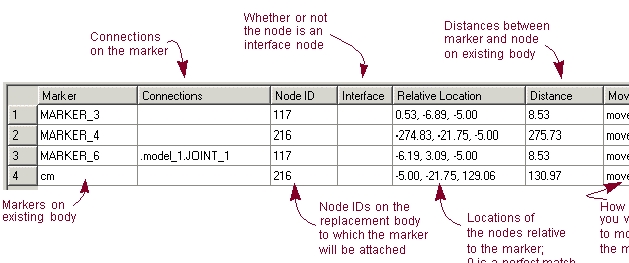
Marker and Node Table when Replacing Rigid Body
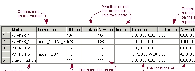
Marker and Node Table When Replacing Flexible Body
Attributes Inherited
When you substitute either a rigid or flexible body for a flexible body, the new flexible body takes on the following attributes of the rigid or flexible body that it replaced:
■Color
■Visibility
■Name visibility
■Icon size
■Exact position initial conditions
■Velocity initial conditions
If you replace a flexible body with another flexible body, the new flexible body also receives the attributes of:
■Selected modes
■Invariant selection
■Modal displacement and velocity initial conditions
■Modal exact displacements
Substitution Limitations
Note the following before you substitute rigid and flexible bodies:
■The closer the geometry of the flexible body matches that of the rigid body, the easier it is to substitute the flexible body for the rigid body.
■When you modify a joint so that it connects to a flexible body instead of a rigid body, Adams View moves the markers defining the attachments to the flexible body at the closest node locations. If the markers are being used by other elements in your model, Adams View leaves the markers at their current locations and creates new markers that connect the joints to the flexible body at the node locations.
As Adams View moves the markers, the joint may appear to be broken. When Adams View simulates the model, its first step will be to repair any broken joints. This may require Adams View to contort the flexible body, and possibly making the simulation fail. You should then move the marker that is not on the flexible body so it coincides with the marker on the flexible body. If this is not possible, bridge the offset between the two markers by creating a massless link that connects the parts (see Using Massless Links) or use an offset marker (see Adding Markers to Flexible Bodies).
■After substituting a body with a (different) flexible body, if one or more analyses which reference the original representation of this body exists in the session, the body will not appear correctly in subsequent animations of those analyses. See Animating After a Flexible Body Swap for details.
Handling of Expressions and Design Variables
When replacing a rigid body with a flexible body, the markers on the rigid body are transferred to the flexible body. By moving the markers, all joints and applied forces on the rigid body will also be moved to the flexible body.
When replacing a rigid body with a flexible body, special treatment is given to the following:
■The center of mass marker on the rigid body is moved to the flexible body. Its position on the flexible body, however, may not be consistent with the flexible body center of mass. The rigid body center of mass marker is also renamed after being transferred to the flexible body.
■Other than the markers, all other children of the rigid body are not transferred to the flexible body. For example, geometry and design points remain on the rigid body.
■When an expression references a rigid part, it automatically will be updated to reference the new flexible body.
■Object type design variables not belonging to the rigid body, but referencing it, will be updated to reference the flexible body. All design variables that are children of the rigid body will not be modified.
Selecting the Existing and Replacement Bodies
You can replace a rigid body with a flexible body that is already in your model or you can specify an MNF or an MD DB to let Adams Flex creates a new flexible body. To replace a flexible body with another flexible body, you must create the replacement flexible body by specifying an MNF or an MD DB.
Learn about:
Selecting Existing Rigid and Replacement Flexible Bodies
To select the bodies:
1. Click the Bodies tab. From the Flexible Bodies, select Rigid to Flex .
.(Classic Interface) From the Build menu, point to Flexible Bodies, and then select Rigid to Flex.
If a rigid body was not selected on the screen, the Database Navigator appears and lets you select the rigid body to be replaced. Learn about the Database Navigator.
The Swap a rigid body for another flexible body dialog box appears.
2. Under the Alignment tab, select how you will specify the replacement flexible body:
■Flex Body, and then select a flexible body that has already been imported into your model. Tips on Entering Object Names in Text Boxes.
■MD DB, select the name of the MD DB, then select the index of the flexible body in DB.
Selecting Existing and Replacement Flexible Bodies
To replace a flexible body with another flexible body, you must create the replacement flexible body by specifying an MNF.
To select the flexible bodies:
1. Click the Bodies tab. From the Flexible Bodies, select Flex to Flex .
.(Classic Interface) From the Build menu, point to Flexible Bodies, and then select Flex to Flex.
The Swap a flexible body for another flexible body dialog box appears.
2. Under the Alignment tab, in the Flexible Body text box, enter an existing flexible body in your model.
3. First select MNF or MD DB in the dropdown box. Then specify the file name in the text box. If you selected an MD DB, you need to specify the Index as well.
Aligning Replacement Body
When replacing rigid or flexible bodies with a replacement flexible body, you have the following options available in the Alignment tab of the Swap a rigid body for another flexible body or Swap a flexible body for another flexible body dialog box for aligning the replacement body with the existing body:
Tip: | To facilitate the alignment, you can select either of the following from the bottom of the Alignment tab: |
■Select View Parts only to display only the existing body and its replacement.
■Select View Topology to display a representation of the existing body and its connections to other parts. Learn about Graphically Viewing Model Topology.
Aligning Center of Mass of Bodies
The Align Flex Body CM with CM of Current Part button aligns the replacement flexible body with an existing body by comparing the center of mass and inertia tensor of the two bodies. The replacement flexible body is:
■Positioned such that its center of mass (CM) is coincident with the flexible body CM.
■Oriented such that its principal inertia directions are coincident with the body's principal inertia directions.
If the inertia properties of the two bodies are similar, this method closely aligns the flexible body with the existing body. If the bodies are symmetric about a plane, this method may rotate the flexible body 180° from the existing body. In this case, you can use the Flip about buttons to rotate the flexible body 180° back into position.
To align the center of mass of the replacement flexible body with that of the existing body:
■In the Alignment tab, select Align Flex Body CM with CM of Current Part
To rotate the flexible body about an axis:
■Select one of the following to rotate the flexible about the corresponding axis:
■X axis - Rotate flexible body 180° about its largest principal inertia direction
■Y axis - Rotate flexible body 180° about its second largest principal inertia direction
■Z axis - Rotate flexible body 180° about its smallest principal inertia direction
Aligning Using Precision Move Dialog Box
The Precision Move dialog box lets you to move bodies by increments or precise coordinates.
To use the Precision Move dialog box to align the bodies:
■In the Alignment tab, select Launch Precision Move Panel. Learn about Moving Objects Using the Precision Move Dialog Box.
Aligning by Defining Three Points
This method uses three unique points to position and orient the flexible body.
To define the alignment by specifying three points:
1. In the Alignment tab, select 3 Point Method.
2. Select a point on the existing body and a point on the flexible body. Adams Flex will position the flexible body so that the point on it is coincident with the point on the rigid body.
3. Now select two more point pairs, one point on each body, to define the x- and y-axes. Adams Flex will orient the flexible body by making points 2 and 3 on the flexible body reside in the plane defined by points 2 and 3 on the rigid body.
Transferring Connections
The following sections explain how to transfer connections from an existing rigid or flexible body to a replacement flexible body:
Changing the Node to Which to Transfer Marker
To change the node to which a marker will be transferred:
1. In the Marker and Node table of the Swap a rigid body for another flexible body or Swap a flexible body for another flexible body dialog boxes, select the row containing the marker.
2. In the Node ID text box, enter the node ID to which you want to transfer the marker.
Tip: | To find a node, select Node Finder to select the Node Finder Dialog Box, and search for all nodes within a specified radius or number of nodes from a given marker. |
3. Select Apply (located to the right of the Node ID text box).
Changing the Location of the Marker
By default, Adams Flex moves the marker to the attachment node specified in the Marker and Node table. If the distance between the attachment node and the marker is nonzero, you may want to preserve the marker location so you do not break any joints on the flexible body or incorrectly define the point of application of a force. In addition, the marker's position may be parameterized. Moving the marker to the chosen attachment node will destroy the parameterization. To prevent this from adversely affecting the flexible body's connectivity with the rest of the model, Adams Flex provides three choices to treat the marker's position:
■Simply move the markers to the location of the specified nodes.
■Transfer the markers but maintain any parameterization that was set up through an Adams View expression to define the location of the marker. This will keep the marker position at its parameterized position.
■Transfer the marker but keep it in its current position, offset from the node. This is helpful if you have defined a joint location using the marker. It keeps the joint from breaking.
To change the location of a marker:
1. In the Marker and Node table of the Swap a rigid body or Swap a flexible body dialog boxes, select the row containing the marker.
2. Select one of:
■Move to node
■Preserve expression
■Preserve location
Adams Flex changes the Move column to reflect the changes.
Replacing the Existing Body
Once you've set the alignment and connections, you can replace the existing body with the replacement flexible body. You can also select to keep the rigid body in the modeling database. Otherwise, Adams Flex deletes the rigid body.
To replace the body:
1. Select Copy original part to keep the existing body in the modeling database for later use.
2. Select OK.
Note: | Adams Flex only transfers markers and any connections they define to the flexible body. It does not transfer string variables and other children of the rigid body. |
Sorting Objects in Marker and Node Table
To help you view the markers and their connections listed in the Marker and Node table, you can sort them based on the headings of the columns. For example, you can sort the table by the marker that is the most distant from its selected node.
To sort objects in the table:
1. In either of the following dialog boxes, select the Connections tab:
2. Set the Sort by option to one of the following:
■Marker - Sort alphabetically by marker name.
■Connections - Sort by those markers with connections.
■Node ID - Sort by the ID of the node.
■Interface - Sort by those nodes that are interface nodes
■Distance - Sort by those markers the most distant from the selected node.
■Move - Sort by the values in the Move column.