Example of Modeling Nonlinear Deformations
Overview
Adams Flex models deformations that are always linear. You can easily model nonlinear deformations, however, by piecing together smaller elements that each deform linearly but together represent nonlinear deformations. This example steps you through how you would model nonlinear deformations.
About the Example
To illustrate how you would model nonlinear deformations, we’ve provided an example based on the problem of the spin-up cantilever beam (“Dynamics of a Cantilever Beam Attached to a Moving Base,” Kane, T.R., Ryan, R.R. and Banarjee, A.K., 1987, Journal of Guidance, Control and Dynamics, Vol.13, No.2). The cantilever beam is shown in Figure 2.
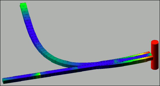
Figure 2 Cantilever Beam
The modal formulation of a flexible body is inherently linear. This example demonstrates how this premature linearization assumption prevents Adams from recognizing the stiffening of the beam due to centrifugal forces. When the nonlinear effects are not modeled, Adams can only predict that the beam will collapse.
To show you how you can avoid this problem, we’ll have you create two beams. One beam you’ll create by piecing together smaller beams and the second beam you’ll create using a single, continuous beam part. You’ll connect both beams to a spinning shaft. You’ll then run a simulation to compare the results for the two types of beams. During the simulation, you’ll discover that the single, continuous beam fails due to divergence.
Starting Adams View and Integrating the MNF
You’ll start the example by running Adams View and creating a new model. You’ll then integrate the MNF into the new model.
To start Adams View and create a database for the flexible body:
1. Copy the file quarter_beam.mnf and full_beam.mnf to your local directory. This file is located in install_dir/flex/examples/mnf, where install_dir is the directory where the Adams software is installed.
2. Start Adams View and create a new model named spin that has no gravity. Use the default units.
Integrating the Short Flexible Beam
Now you’ll integrate the MNF containing a definition of a short flexible beam to be used as the base for the sectioned beam. You’ll also disable several of its modes. You’ll disable its modes before you copy the beam so that each copy has the appropriate modes disabled.
To import the beam:
1. Import quarter_beam.mnf into your model using the default damping ratio. Name the flexible body SHORT_1.
A 500 mm solid element beam appears.
2. To see the flexible body more clearly, color it yellow. To color it, select the flexible body, and then, from the Entity Color tool stack in the Main toolbox, select the color yellow.
3. Display the Flexible Body Modify dialog box.
4. Select Modal ICs.
The Modify Modal ICs dialog box appears as shown below.
5. Disable all modes except 8, 11, 14, 15, 19, 23, 27, 29, 30, and 32.
6. Select Close.
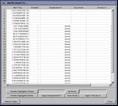
Figure 3 Modify Modal ICs Dialog Box
Assembling a Sectioned Beam
Now you’ll copy the beam three times, adding each copy to the end of the next. Finally, to assemble a sectioned beam, you’ll attach the beams to each other using fixed joints.
1. Select the SHORT_1 geometry.

3. In the Move container, select the Selected, Copy, and From To options.
4. Following the instructions in the status bar, select Node 1000 at the left end of the flexible body for the point to move from and Node 1001 at the right end as the point to move to.
A second flexible body appears at the right end of the first flexible beam.
5. Repeat Steps 2 through 4 two more times until you have four flexible bodies arranged end-on-end to form a 2000 mm beam. You may want to zoom out on the view or translate the view to see all the beams.
6. To ensure that the segments are correctly copied, select the last one and select the Info tool  on the Status Toolbar. Verify that the list of selected modes includes only 8, 11, 14, 15, 19, 23, 27, 29, 30, and 32.
on the Status Toolbar. Verify that the list of selected modes includes only 8, 11, 14, 15, 19, 23, 27, 29, 30, and 32. 7. Create three fixed joints using the 1 Location construction method and attach the flexible bodies to each other at Nodes 1000 and 1001 as shown in Figure 3 on page 6.
Tip: | It is easier to see the nodes on the flexible bodies if you set each beam to a different color. |
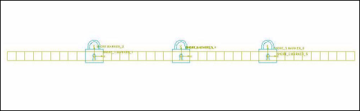
Figure 4 Four Flexible Bodies Arranged End-on-End
Building a Single Flexible Body Beam
Now, you’ll integrate a single flexible beam, called LONG, into your model and disable some of its modes.
To integrate the beam into Adams View:
1. Integrate the file full_beam.mnf and rename it LONG_1 using the default damping ratio. The new beam should be superimposed over the sectioned beam. You can use the Select List command on the Edit menu to select LONG_1 if you cannot select it in the window.
2. Color the geometry LONG_1 red so that it contrasts well with the sectioned beam.
3. Disable all modes on the geometry LONG_1 except 8, 10, 12, 15, 18, 20, 22, 24, 28, 29, and 31.
Adding a Spinning Shaft
In this section, you’ll create a spinning shaft from cylinder geometry and create a motion generator on the shaft.
To create a spinning shaft:
1. Click the Bodies tab. From the Solids container, select the Cylinder tool  . Create a cylinder approximately 500 mm long, 50 mm in diameter, and aligned with the global y-axis. Position it flush with the left end of the two beams as shown in the figure below.
. Create a cylinder approximately 500 mm long, 50 mm in diameter, and aligned with the global y-axis. Position it flush with the left end of the two beams as shown in the figure below. 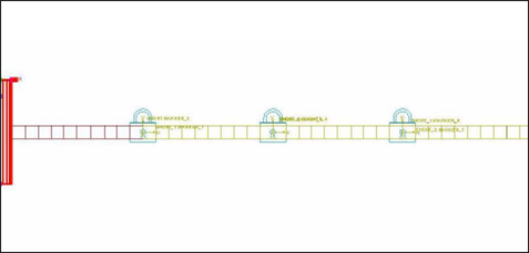
Figure 5 Spinning Shaft
2. Fasten the two beams to the cylinder using two fixed joints. Use the 2 Bod - 1 Loc construction method.
3. View your model from the top by pressing T.
4. Click the Connectors tab. Select Joints container and select the Revolute tool  . Create a revolute joint between the cylinder center of mass and ground. Before creating the revolute joint, turn off the grid to ensure that the revolute joint aligns normal to the view.
. Create a revolute joint between the cylinder center of mass and ground. Before creating the revolute joint, turn off the grid to ensure that the revolute joint aligns normal to the view. 5. Right-click the revolute joint. From the pop-up menu that appears, point to the joint corresponding to the revolute joint, and then select Modify.
6. In the Modify Joint dialog box, select Impose Motion(s).
7. In the Impose Motion dialog box, from the pull-down menu next to Rot Z, select acce(time).
8. In the text box that appears directly to the right of the pull-down menu, enter:
6/15*(1-COS(2*PI*TIME/15))
9. Be sure that the displacement and velocity initial conditions (Disp. IC and Velo. IC) are zero (the default).
10. Select OK.
11. Select OK.
Simulating the Beams
In this last step, you’ll simulate the two beams to see how they respond.
To simulate the beams:
1. Center the cylinder in the view and zoom out to allow the beam to stay in the view as it spins. You may also want to switch to a top view so that you can see it spin better.
2. Simulate for 15 seconds with 1000 output steps.
This simulation will take approximately 15 minutes, depending on your hardware. Since the movement of the beam starts gradually, you will not notice any motion in the first few seconds of the simulation. Also note that the simulation fails at approximately 10 seconds due to divergence of the single, continuous beam.
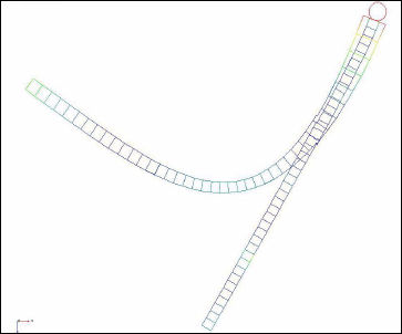
Figure 6 Results of Simulation
Animating the Results from a Top View
Now, to see the cantilever beam spin, you’ll run an animation of the results from a top view.
To animate from top view:
1. In the main window, press T.
2. Click Animation tool.
3. Select the Play tool. 
You will notice that the single, long beam deforms unrealistically because Adams assumes linear deformations. If you want to simulate nonlinear behavior, you need to break a flexible body into segments that behave linearly as you have done here with the sectioned beam.