Preprocess Ball Bearing FE mesh
Machinery → Bearing AT → Ball Bearing → Preprocessing → Mesh
Bearing AT has a built-in catalogue of many bearings, and after selecting any bearing based on the internal diameter, the macro-geometry of the selected bearing is automatically calculated.
In Create mode you define a new property file by selecting one of available bearings from catalogue and calculating the macro-geometry by using Compute geometry button. This can be also done by entering the basic bearing dimensions (inner diameter, outer diameter, bearing width) and the static load rating.
In Edit mode is possible to load already existing property file and change the macro-geometric parameters of the bearings manually. How to proceed not only in the Edit mode case, is explained in the following steps in Bearing AT Online Help. Meaning of all required input parameters is explained below.
In both modes, it is possible to make a preview of bearing macro-geometry. There are also sketches, which show the meaning of each macro-geometry parameter.
This dialog box allows you to create ball bearing property file (*.bpf) or modify existing one. There are geometrical data of the bearing stored in this file. This preprocessing step will automatically generate FE meshes of bearing inner and outer ring and rolling element and submit Nastran computation (SOL101) which provides intermediate results (*.PCH) required for contact preprocessing.
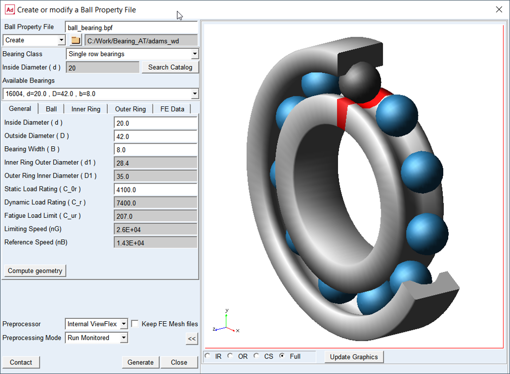
Figure 5 Deep groove ball bearing geometry preview
Main
For the options | Do the following |
|---|---|
Ball Property File | Enter the name or browse for the ball property file (*.bpf). It contains input for geometry and material data. |
Create/Edit mode | Choose one of the options. In Create mode you can choose from a wide range of catalogue bearings. In Edit mode you can load existing *.bpf file and adjust bearing macro-geometrical parameters. |
Destination folder | It is possible to select the destination folder for saving the property files via the button with the folder icon. |
Bearing Class | Select from available classes. |
Inside Diameter (d) | Enter the required inner diameter of the bearing. |
Search Catalogue | Click on this button after the internal diameter of the bearing has already been entered. |
Available Bearings | From option menu select one of required bearings. |
Compute geometry | Click on Compute geometry button - all required values in all tabs will be calculated. |
Preview >> | Show preview of bearing geometry after filling all parameters (Figure 5). |
Preprocessor | Select one of following options. ■External ViewFlex: use this option when there is no Nastran installation available. On background there is SOL101 running by Adams embedded Nastran Solver ■External Nastran: use this option when you have Nastran installation available. This option allows you to continue working since standalone Nastran is executed in external shell window hence the main window remains active. Please note that additional Nastran license is required. It makes use of Nastran SMP license if available. This option is not available on linux ■Internal Nastran: use this option when you have Nastran installation available. It makes use of Nastran SMP license if available ■Mesher Only: use this option to verify that FE Mesh is valid before running SOL101 |
Preprocessing Mode | Select one of following options for running mesh pre-processor. ■Run Quiet: executes mesher without any output to the screen ■Run Monitored: executes mesher with output to the screen ■Files Only: the batch file is created but not submitted to execution, one has to launch it manually |
Contact | Open contact preprocessing dialog box after FE meshes are created and Nastran SOL101 is completed (Preprocess Ball Bearing Contact ) |
Ball
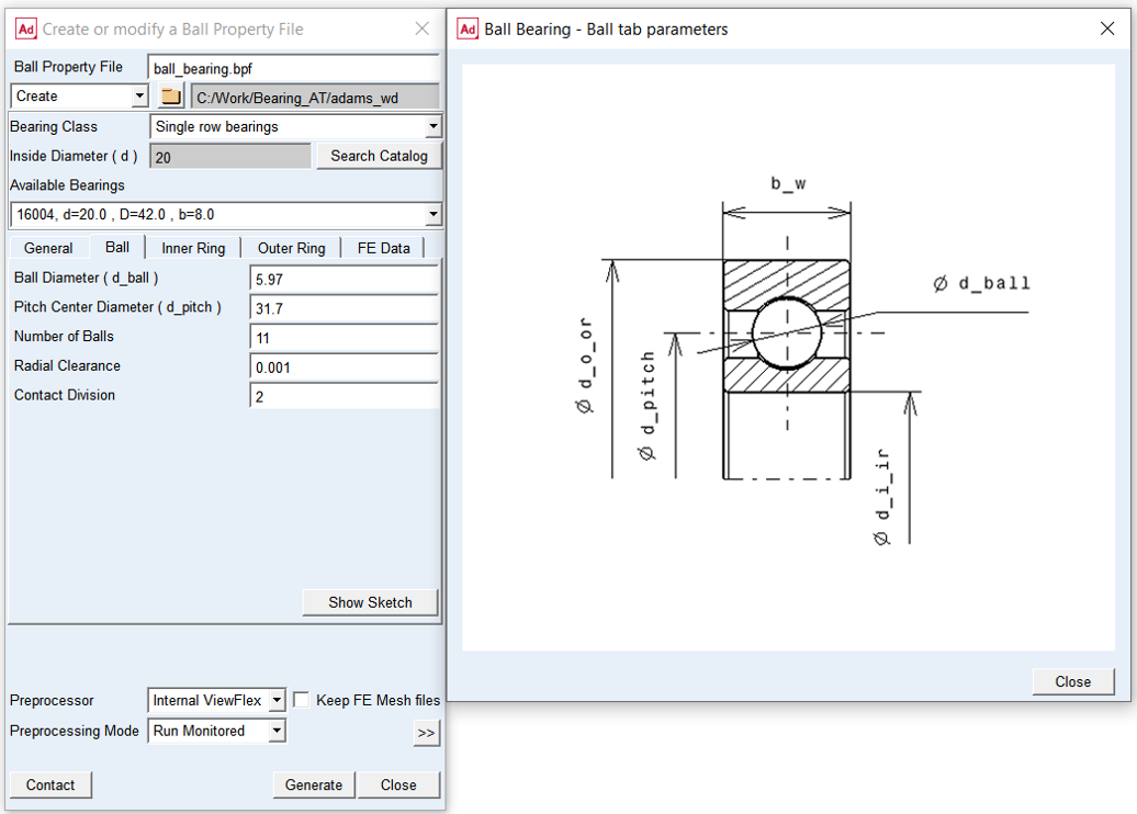
Figure 6 Ball tab and geometry
For the options | Do the following |
|---|---|
Ball Diameter ( d_ball ) | Enter the ball diameter. |
Pitch Centre Diameter ( d_pitch ) | In the design position, all centres of the balls are located on the pitch centre diameter. |
Number of Balls | The number of virtual rolling elements for the bearing element. |
Radial Clearance | The radial clearance is defined in the design position. It is the total clearance. |
Contact Division | Define size of load mesh for contact definition. Set value either to 1 or 2. |
Inner Ring
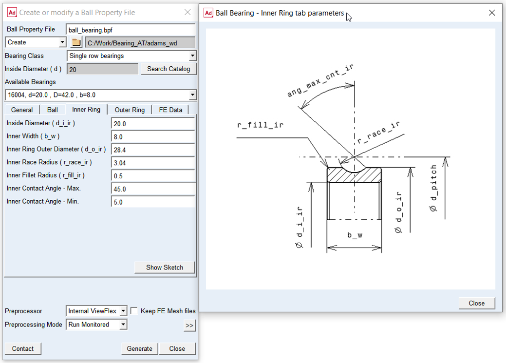
Figure 7 Inner ring tab and geometry
For the options | Do the following |
|---|---|
Inside Diameter ( d_i_ir ) | The inner diameter of the inner ring fits normally to a shaft or a pin. |
Inner Width ( b_w ) | Width of inner ring. |
Inner Ring Outer Diameter ( d_o_ir ) | The outer diameter of the inner ring has to be smaller than the pitch diameter and larger than the inside diameter. |
Inner Race Radius ( r_race_ir) | The inner race radius has to be slightly larger than the ball radius. The ratio between 'inner race radius' and ball radius is often selected between 1.02 and 1.03; however it may be different to fulfil specific design requirements. |
Fillet Inner Radius ( r_fill_ir ) | The fillet is between the inside diameter and the flanges of a ring. |
Inner Contact Angle - Max. ( ang_max_cnt_ir ) | The maximum angle of inner contact defines the size of the contact patch on the ball surface. It represents half of the angle of the contact patch along the race radius - bearing axial (XZ) plane; supported range of values are 5 to 45 [degrees]. |
Inner Contact Angle - Min. | The minimum angle of inner ring defines the size of the contact patch on the ball surface. It represents the angle of the contact patch along the ring circumference - bearing normal (XY) plane; supported values are 4 to 10 [degrees]. |
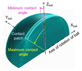
Figure 8 Contact patch and contact angles on the ball
Outer Ring
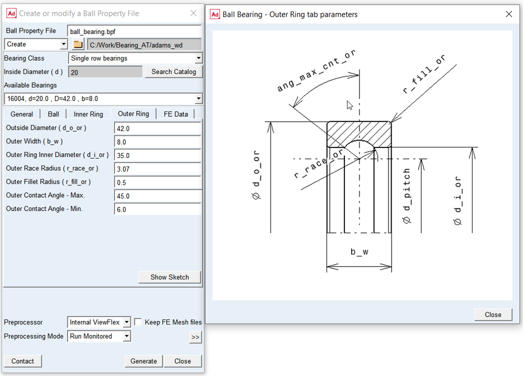
Figure 9 Outer ring geometry
For the options | Do the following |
|---|---|
Outside Diameter ( d_o_or ) | The outer diameter of the outer ring fits normally to a bore in a housing. |
Outer Width ( b_w ) | Width of outer ring. |
Outer Ring Inner Diameter ( d_i_or ) | The inner diameter of the outer ring has to be larger than the pitch diameter and smaller than the outer diameter. |
Outer Race Radius ( r_race_or ) | The outer race radius has to be slightly larger than the ball radius. The ratio between 'outer race radius' and ball radius is often selected between 1.05 and 1.06; however it may be different to fulfil specific design requirements. |
Outer Fillet Radius ( r_fill_or ) | The fillet is between the outer diameter and the flanges of ring. |
Outer Contact Angle - Max. ( ang_max_cnt_or ) | The maximum angle of outer contact defines the size of the contact patch on the ball surface. It represents half of the angle of the contact patch along the race radius - bearing axial (XZ) plane; supported values are 5 to 45 [degrees]. |
Outer Contact Angle - Min. | The minimum angle of inner ring defines the size of the contact patch on the ball surface. It represents the angle of the contact patch along the ring circumference - bearing normal (XY) plane; supported values are 4 to 10 [degrees]. |
FE Data
For the options | Do the following |
|---|---|
Young’s Modulus | Enter Young‘s Modulus bearing material The Young‘s Modulus E defines the relation between tensile strain e and tensile stress S by Hooke’s law; see equation below. For more detailed information: see literature about ‘theory of elasticity’ S = E * e Young's modulus for steel is around 2.1E5 N/mm^2 |
Poisson’s Ratio | Enter Poisson's Ratio bearing material An extension ex of a linear elastic material is accompanied by lateral strains ey and ez. Poisson's ratio ν defines this relation by following equations ey = -ν * ( ex / E ) ez = -ν * ( ex / E ) Poisson's ratio can also be derived from the shear modulus G, please look at the literature for more details. G = E / ( 2 * ( 1 + ν) ) Poisson's ratio ν for steel is around 0.3. |
Mass Density | Enter Mass Density bearing material The mass m of a solid body is computed from its volume V multiplied by the Mass Density r. m = V * r Mass Density for steel is around 7.8E-6 kg/mm^3 |