Pulley Set
The Pulley set consist of the following options:
Poly-V Grooved
Poly-V Pulley
The poly-v grooved belt system employs a cord-reinforced belt which is grooved along its primary axis on one side, to mate with similarly grooved pulleys, and smooth on the other (back) side.
Schematic Representation of Poly-V Pulley | Poly-V Pulley Geometry  |
Belt
Poly-V Belts provide smooth running, low noise operation at high speeds, small pulley diameters and large transmission ratios. Poly V-Belts are also called "Multi Ribbed Belts." The back side of the Poly-V Belt (that is, side which does not contact a Poly-V Pulley) is smooth.
Methods
The following methods are available for modeling Poly-V Grooved type belt systems.
1. Constraint
This is a simple method used to transmit the velocity through a ratio. This method is used when forces and components involved are neglected and only speed reduction or multiplication is of interest.
2. 2D Links
The belt is constrained to a plane. The belt is modeled with planer part segments connected to each other with stiffness elements and analytically calculated contact forces between the segments and pulleys. This modeling method is faster to simulate than 3D links but the axis of rotation must be parallel to one of the global axes.
3. 3D Links
The belt is constrained to a plane. The belt is modeled with 3D part segments connected to each other with stiffness elements and analytically calculated contact forces between the segments and pulleys. Use this method when the axis of rotation is not parallel to one of the global axes.
Trapezoidal Toothed
Pulley
The Trapezoidal Pulley is so named due to its continuous trapezoidal shaped teeth. As a result, the profile of the pulley teeth is involute. The pulley must reference a trapezoidal toothbelt component.
Schematic Representation of Trapezoidal Pulley | Trapezoidal Pulley Geometry 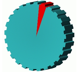 |
Belt
The trapezoidal toothbelt property is an array referenced by pulleys. It contains all belt parameters. To create the belt segments, you have to wrap the belt. Belt type must reference Pulley of similar type.
Methods
The following methods are available for modeling Trapezoidal Toothed type belt systems.
1. Constraint
This is a simple method used to transmit the velocity through a ratio. This method is used when forces and components involved are neglected and only speed reduction or multiplication is of interest.
2. 2D Links
The belt is constrained to a plane. The belt is modeled with planer part segments connected to each other with stiffness elements and analytically calculated contact forces between the segments and pulleys. This modeling method is faster to simulate than 3D links but the axis of rotation must be parallel to one of the global axes.
3. 3D Links
The belt is constrained to a plane. The belt is modeled with 3D part segments connected to each other stiffness elements and analytically calculated contact forces between the segments and pulleys. Use this method when the axis of rotation is not parallel to one of the global axes.
Smooth
Pulley
Also known as a flat belt system, the smooth belt system employs a cord-reinforced belt which is smooth on both sides wound through a series of smooth pulleys.
Belt
Also known as "Flat belt drives," these can be used for a large amount of power transmission and there is no upper limit of distance between the two pulleys. It is smooth and flat on both sides and it is more efficient than Poly-V Belt.
Note: | Checking general parameters on individual pulleys. ■Pulley_set holds the information of type and number-of-pulleys in respective pulley_set. Details of individual pulley may be different and needs to be checked in through database-navigator as shown below (Individual pulleys are not shown in model_browser): |
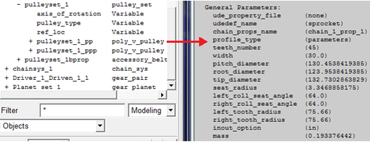 | |
See section Viewing Object Information Through Database Navigator for more information. | |
Methods
The following methods are available for modeling Smooth type belt systems.
1. Constraint
This is a simple method used to transmit the velocity through a ratio. This method is used when forces and components involved are neglected and only speed reduction or multiplication is of interest.
2. 2D Links
The belt is constrained to a plane. The belt is modeled with planer part segments connected to each other with stiffness elements and analytically calculated contact forces between the segments and pulleys. This modeling method is faster to simulate than 3D links but the axis of rotation must be parallel to one of the global axes.
3. 3D Links
The belt is constrained to a plane. The belt is modeled with 3D part segments connected to each other stiffness elements and analytically calculated contact forces between the segments and pulleys. Use this method when the axis of rotation is not parallel to one of the global axes.
4. 3D Links Nonplanar
The belt is modeled with 3D part segments connected to each other with stiffness elements and analytically calculated contact forces between the segments and the pulleys. The belt can move laterally across the pulleys and accommodate small amounts of out of plane offset and misalignment in the pulleys.
Note: | When pulleys are misaligned (that is, rotated out of plane relative to each other), the belt segments will not be rotated to match the alignment of all the pulleys after wrapping; an initial static equilibrium analysis should be run, after which the belt segments should align properly. |
5. 3D Simplified
Instead of a large number of discrete elements, the belt is represented by an inventive set of parts, constraints and forces to represent belt axial compliance, belt bending, roller friction and mass transport effects. Use this method when effects of the belt mass and inertia can be neglected since it will solve much faster than the discretized methods. These effects can often be neglected when one is uninterested in transverse belt dynamics. This method does not support continuous, unrestricted simulation of closed-loop systems. It is better for reciprocating systems or certain closed-loop systems where belt motions of no more than a few spans of the maximum roller-roller distance are simulated.