Create / Modify Bearinx Roller Element
The create dialog box allows you to create Bearinx bearing element (see Figure 120). The bearing geometrical parameters are displayed in the Bearing Specifications part of the dialog box.
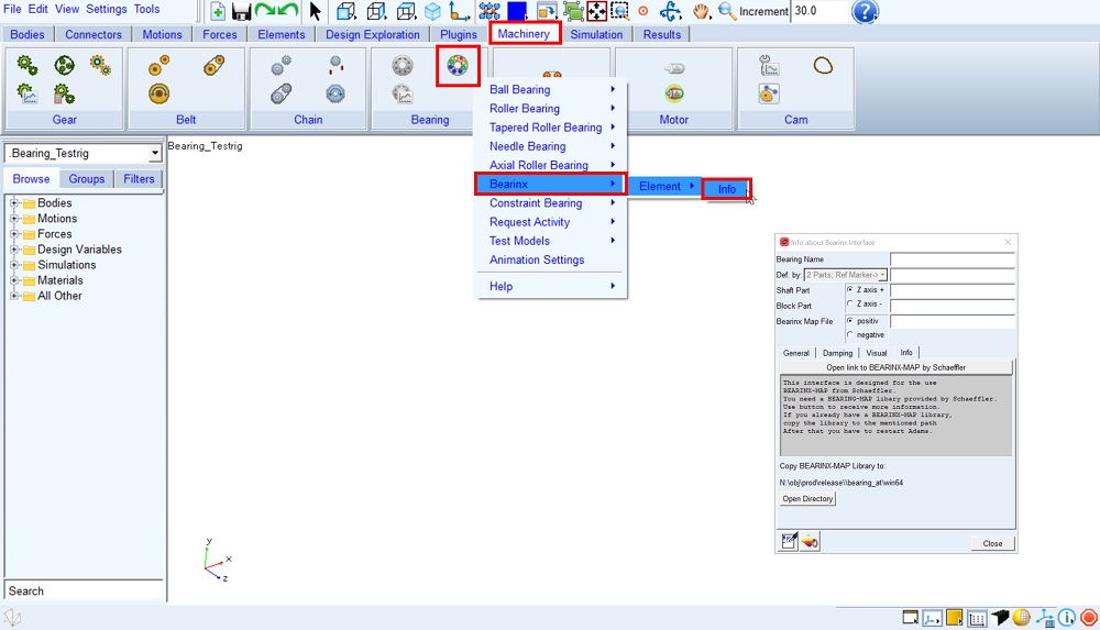
Figure 120 Bearinx menu (dialog box – Info about Bearinx Interface)
Main
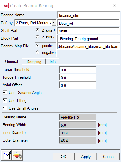
Figure 121 Create Bearinx bearing element – general tab
For the options | Do the following |
|---|---|
Bearing name | Enter the name of the bearing |
Def by. | Select the method of bearing element creation 2 Parts; Ref Marker -> Select the reference marker to locate and orient new bearing element on any part; select shaft part and block part to attached new bearing element 2 Markers -> Select markers on shaft part and block part to locate and orient new bearing element |
For the 2 Parts; Ref. Marker option you need to specify the Shaft Part and Block Part and one Reference marker to define unique location. | |
Ref. Marker | Select the bearing reference marker to define unique location and orientation of the bearing element. Note: The orientation of the Z axis can be flipped by the “Z axis +” / ”Z axis –” radio button. In this release of Bearinx interface, the bearing element uses the opposite direction to define axially asymmetrical bearings than Bearing AT does (axial roller bearings, roller bearing with collar). This will be changed in a future release. |
Shaft Part | Select the shaft part in your model to attach the bearing inner ring to. The marker will be automatically created on the selected part. |
Block Part | Select the block part in your model to attach the bearing outer ring to. The marker will be automatically created on the selected part. |
For the 2 Markers option you need to specify the Shaft Marker and Block Marker on respective parts to define both, the connectivity and location / orientation of the bearing element. Note: With this option you effectively define initial displacement of bearing rings relative to each other. | |
Shaft Marker | Select a marker on the shaft part in your model to attach the bearing inner ring to. |
Block Marker | Select a marker on the block part in your model to attach the bearing outer ring to. This is reference marker of bearing. |
Bearinx Map File | Specify bearinx file (*.bxm) |
General
Figure 122 Create Bearinx bearing element – general tab
For the options | Do the following |
|---|---|
Force Threshold | Enter the value for the threshold. All values that are smaller in amount are set to 0. |
Torque Threshold | Enter the value for the threshold. All values that are smaller in amount are set to 0. |
Use Dynamic Angle | Toggle ON or OFF to take rotation of the rolling element set into account (ON=yes, OFF=no) |
Use Tilting | Toggle ON or OFF to take tilting into account (ON=yes, OFF=no) |
Use Small Angles | Toggle to switch between small angles or large angles model. ON: Small angles. The angles represent small rotations. OFF: Big angles. The input data describe a coordinate transformation (cardan angle alpha- x, beta-y, gamma-z). |
Bearing Specification | Values read in from a *.bxm file are not editable and are used in graphical representation of the bearing element in Adams View: Bearing Name - Name of the Bearing Outer Diameter - Outer Diameter of the Bearing (mm) Inner Diameter - Inner Diameter of the Bearing (mm) Width - Width of the Bearing (mm) |
Damping
In the Damping Type option menu you can choose from three available choices; see Figure 123. Options Adams Bushing and Bearinx Damping are exclusive.
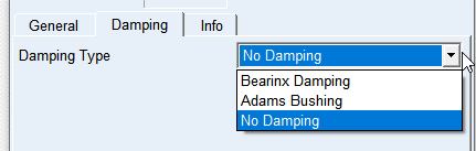
Figure 123 Damping tab option menu
For the Bearinx Damping option the damping calculation from the Bearinx Solver is used.
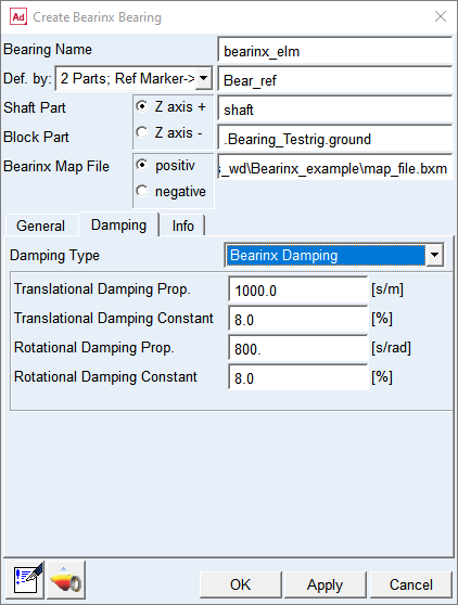
Figure 124 Damping tab - Bearinx Damping option
For the options | Do the following |
|---|---|
Translational Damping Prop. | Enter the value for Translational Damping proportional Factor in [s/m] units. |
Translational Damping Constant | Enter the value for Translational Damping constant in [%] |
Rotational Damping Prop. | Enter the value for Rotational Damping proportional Factor in [s/rad] |
Rotational Damping Constant | Enter the value for Rotational Damping constant in [%] |
Extended definition
Damping Force Fd is defined by following formula:
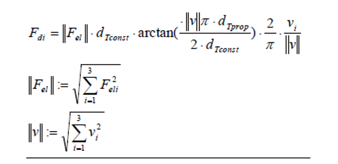
Where:
i – component direction x, y, z
vi - translational speed in direction i
Fel – rolling element load
dTconst - Translational Damping Constant
dTprop - Translational Damping proportional Factor
Damping Torque Md is defined by following formula:
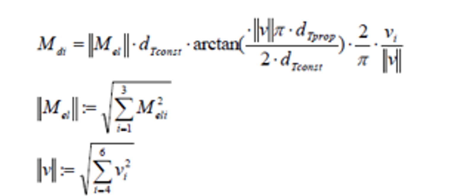
Where:
i – component direction x, y, z
vi - rotational speed around direction i
Mel – rolling element torque
dTconst - Rotational Damping Constant
dTprop - Rotational Damping proportional Factor
If no damping parameters are specified, dTconst is set to 0.08 and dTprop to 1000 s/m or 800 s/rad. The damping is only for the numerical stability of the simulation hence it does not depict any physical damping.
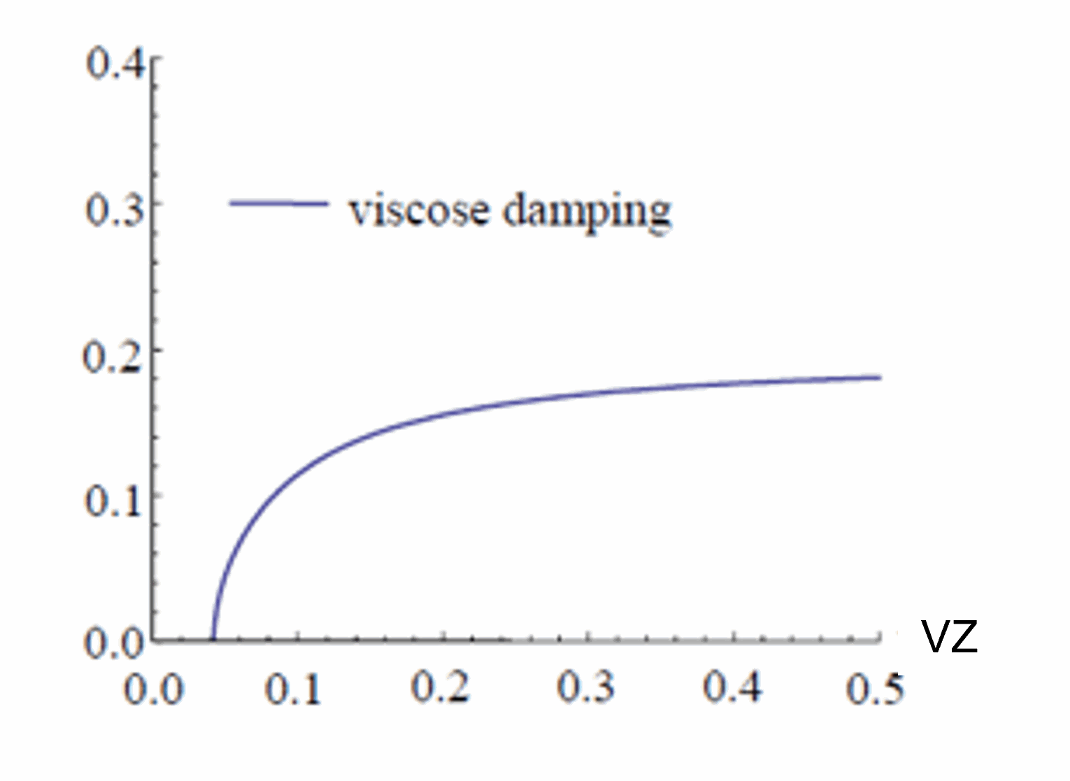
Figure 125 Bearinx viscose damping
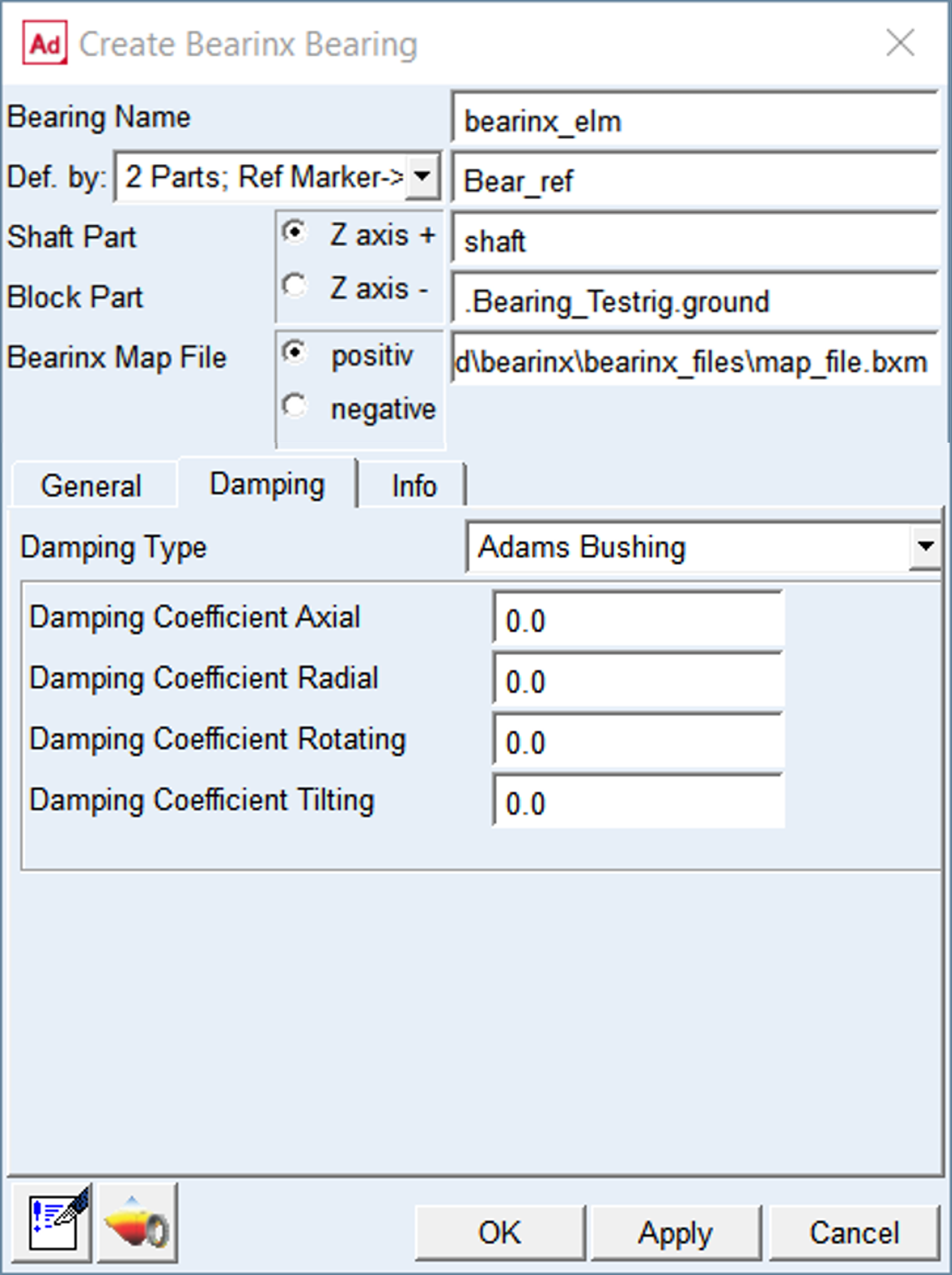
Figure 126 Damping tab - Adams Bushing option
For the Adams Bushing option a standard Adams bushing is used to model the damping force. See BUSHING statement in Adams solver online help for more details.
The force due to damping is zero when there are no relative translational velocities between the markers on the action and reaction bodies.
The torque due to damping is zero when there are no relative rotational velocities between the markers on the action and reaction bodies.
For the options | Do the following |
|---|---|
Damping Coefficient Axial | Enter viscous-damping coefficient for axial direction in model units of [force-time per unit displacement] |
Damping Coefficient Radial | Enter viscous-damping coefficient for radial directions in model units of [force-time per unit displacement] |
Damping Coefficient Rotating | Enter viscous-damping coefficient for the rotating axis in model units of [torque-time per radian] |
Damping Coefficient Tilting | Enter viscous-damping coefficient for the tilting axes in model units of [torque-time per radian] |
Visual
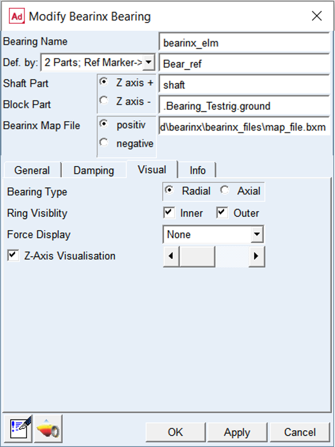
Figure 127 Modify Bearinx Bearing element – Visual tab