Create / Modify Roller Bearing element
Machinery → Bearing AT→ Roller Bearing → Element → New/Modify
The dialog box allows you to create Adams View roller bearing element. The bearing geometrical parameters are displayed in the Basic Dimensions from Property File part of the General tab.
Main
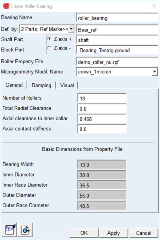
Figure 48 Create roller bearing element dialog box - general tab
For the options | Do the following |
|---|---|
Bearing Name | Enter the name of the bearing |
Def. by. | Select the method of bearing element creation ■2 Parts; Ref Marker -> Select the reference marker to locate and orient new bearing element on any part; select shaft part and block part to attached new bearing element ■2 Markers -> Select markers on shaft part and block part to locate and orient new bearing element Note: Z-axis of reference marker defines rotational axis of bearing element. |
For the 2 Parts; Ref. Marker option you need to specify the Shaft Part and Block Part and one Reference marker to define unique location. | |
Ref. Marker | Select the bearing reference marker to define unique location and orientation of the bearing element. Note: The orientation of the Z axis can be flipped by the "Z axis +" / "Z axis -" radio button. |
Shaft Part | Select the shaft part in your model to attach the bearing inner ring to. The marker will be automatically created on the selected part. |
Block Part | Select the block part in your model to attach the bearing outer ring to. The marker will be automatically created on the selected part. |
For the 2 Markers option you need to specify the Shaft Marker and Block Marker on respective parts to define both, the connectivity and location / orientation of the bearing element. Note: With this option you effectively define initial displacement of bearing rings relative to each other. | |
Shaft Marker | Select a marker on the shaft part in your model to attach the bearing inner ring to. |
Block Marker | Select a marker on the block part in your model to attach the bearing outer ring to. This is reference marker of bearing. |
Roller Property File | Specify the roller bearing property file (*.rpf) |
Microgeometry Modif. Name | Select one of the contact property files including micro-geometry variants you have preprocessed previously. |
General
For the options | Do the following |
|---|---|
Number of Rollers | You can adjust the value of input for the preprocessing phase for Adams simulation. Default value as specified in the *.rpf property file; a maximum of 150 rollers is supported. |
Total Radial Clearance | It is radial operating clearance determined on a fitted bearing still warm from operation. It is defined as the amount by which the inner ring can be moved in a radial direction from one extreme position to the other in relation to the outer ring. The total radial clearance can be positive or negative. In case of negative clearance, the rolling elements are already preloaded at the design position. The default value is 0.0 |
Axial Clearance to inner collar | Enter the axial clearance to the inner collar. Inner ring is free to move relative to outer ring in positive Z direction however can make contact in negative Z direction as rollers penetrate to the collar of inner ring. Axial clearance represents distance of rollers from collar measured in design position of bearing. Default value is 5% of roller length. |
Axial Contact Stiffness | It represents stiffness per roller for contact between inner ring and outer ring axial movement along negative Z direction measured in the bearing reference marker. Default value is 0.0 [Force/Length] in model units. |
Damping
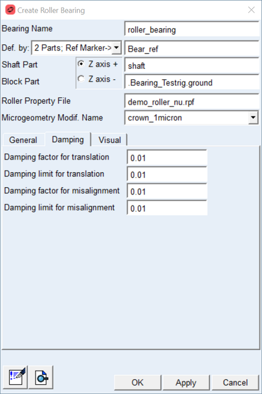
Figure 49 Roller bearing element dialog box Damping tab
For the options | Do the following |
|---|---|
Damping Factor for translation | Damping force is applied per roller, when the compression of the roller is increasing. The damping force is defined by following equation Damping_force = roller_load * ( tran_velocity * damping factor ) Default: 0.01 |
Damping Limit for translation | If the expression ( tran_velocity * damping factor ) exceeds the Damping Limit, then the damping force is becoming: Damping_force = roller_load * damping limit Note: Very high damping can slow down the integrator. The Damping Limit was introduced to prevent unintentional high damping. Default: 0.01 |
Damping factor for misalignment | Damping torque is applied per roller, when the compression of the roller is increasing. The damping torque is defined by following equation Damping_torque = roller_torque * ( ang_velocity * damping factor ) Default: 0.01 |
Damping limit for misalignment | Damping torque is applied per roller, when the compression of the roller is increasing. The damping torque is defined by following equation Damping_torque = roller_torque * ( ang_velocity * damping factor ) Note: Very high damping can slow down the integrator. The Damping Limit was introduced to prevent unintentional high damping. Default: 0.01 |
Visual
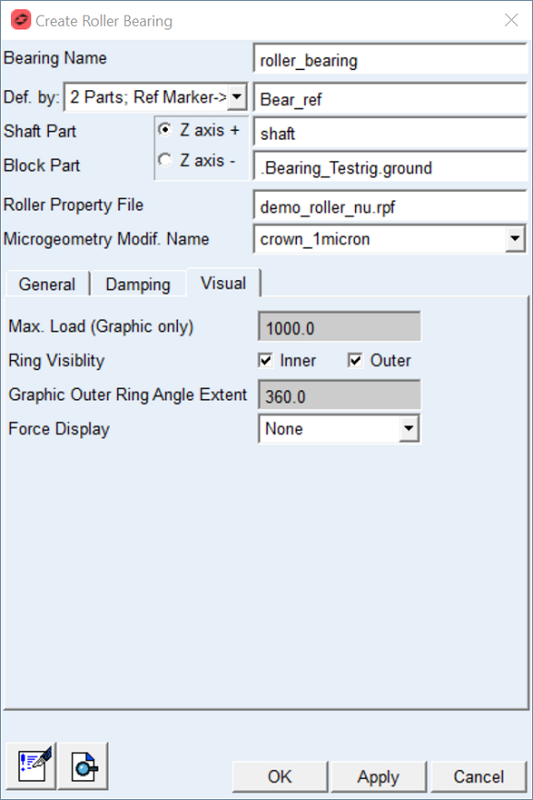
Figure 50 Roller bearing element dialog box - Visual tab
For the options | Do the following |
|---|---|
Max.load (Graphics Only) | Enter value of maximum roller load. This parameter is used as load threshold for animations, when color of the rollers indicate the level of loading. The roller is colored red, when the roller load reaches the value of specified load. |
Ring Visibility | Toggle ON or OFF to put the Inner and Outer ring visible or invisible state |
Graphic Outer Ring Angle Extent | Adjust this parameter to take a look into the bearing (Figure 52). A portion of the outer ring from this input till 360 degrees is not displayed. |
Force Display | Set to whether you want to display force graphics for shaft part or none. |
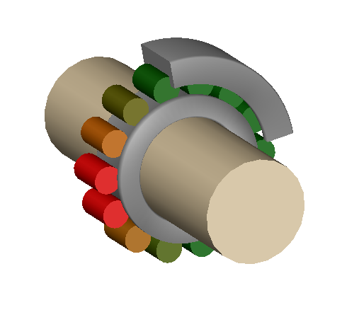
Figure 51 Max. load color coding
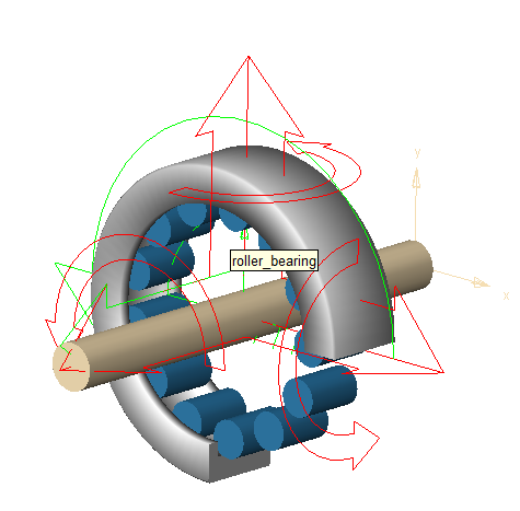
Figure 52 Graphics outer ring and ring visibility