Create Chain - Roller
Machinery → Create Chain
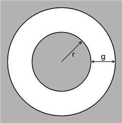
The gap length is defined as the length g on the figure below:
Where:
■r is the inner radius
■g is the gap size
■DM is the displacement of the center of the inner circle relative to the center of the outer circle.
■VR is the radial velocity between the centers
L
For the option | Do the following |
|---|---|
If you select Linear compliance, the following options will be displayed: | |
Chain | |
Name | Enter the chain name. |
Axis of Rotation | Axis of Rotation can be one of the following: ■Orientation ■Pick (Marker) ■Global Z ■Global X ■Global Y |
Reference location | Enter the reference location. This will be used as a reference frame to build other chain components. |
Geometry | |
Total Links | Select to directly specify the number of links in the chain. By default, this is un-selected and Adams Machinery will automatically calculates the number of links for which, based on the chain routing, the lowest positive tension will result. This field is primarily intended for use-cases where a maximum of 1 or 2 extra links beyond the default calculated number of links is desired. Be advised that such models may have difficulty reaching a static equilibrium solution. Use of the static funnel technique may be necessary to solve for equilibrium. |
Link type | Select one of the following: ■Uniform Link - Use this option, if all links are identical, to specify the mass properties of one link. ■Multi Links - Use this option to specify the material properties of two link designs, which will alternate in the chain. |
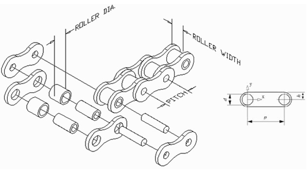
Chain pitch | Enter the distance, p, between the center lines of the two rollers on a chain link. |
Chain width | Enter the width of the chain links. |
Pitch to back | Enter the distance, h, from the pitch line of the chain link to edge of the plate that will be in contact with a guide. |
Roller Diameter | Enter the diameter, d, of the link connecting rollers. |
Chain Pitch 2 | Enter the distance, p, between the center lines of the two rollers on a chain link. |
The Linear Chain Connection Parameters define the stiffness and damping of the bushing connecting two links. You can measure the chain tension by creating requests (see Create/Modify Chain Link Request or Create/Modify Span Request for Roller and Silent Chain. | |
Link stiffness | |
Translational (X) | ■Stiffness Enter the stiffness of the chain link connections in the x direction (along the chain). This is the K[r1] value of a BUSHING statement. The stiffness is in force units/length units. ■Damping Enter the damping coefficient of the chain link connections in the x direction (along the chain). This is the C[r1] value of a BUSHING statement. The damping is in force units * time units/length units. |
Rotational (Z) | ■Damping Enter the rotational damping coefficient of the chain link connections around the z-axis; that is, the center axes of the rollers. This is the CT[r3] value of a BUSHING statement. The damping is in force units * length units * time units/angle units. |
If you select Non-Linear compliance, the following options will be displayed: | |
Name | Enter the chain name. |
Axis of Rotation | Axis of Rotation can be one of the following: ■Orientation ■Pick (Marker) ■Global Z ■Global X ■Global Y |
Reference location | Enter the reference location. This will be used as a reference frame to build other chain components. |
Geometry | |
Link type | Select one of the following: ■Uniform Link - Use this option, if all links are identical, to specify the mass properties of one link. ■Multi Links - Use this option to specify the material properties of two link designs, which will alternate in the chain. |
Chain pitch | Enter the distance, p, between the center lines of the two rollers on a chain link. |
Chain width | Enter the width of the chain links. |
Pitch to back | Enter the distance, h, from the pitch line of the chain link to edge of the plate that will be in contact with a guide. |
Roller Diameter | Enter the diameter, d, of the link connecting rollers. |
Stiffness The Nonlinear Chain Connection Parameters define the stiffness and damping of the field connecting two links. | |
Translational (X) | |
Stiffness | Enter the three parameters that specify a nonlinear function for the translational stiffness of the link connections in the x direction (along the chain). The parameter: ■K1 is in force units/length units ■K2 is in force units/length units**3 ■K3 is in force units/length units**5 |
Damping | Enter the damping coefficient of the chain link connections in the x direction (along the chain). The damping is in force units * time units/length units. |
Rotational (Z) | |
Damping | Enter the rotational damping coefficient of the chain link connections around the z-axis; that is, the center axes of the rollers. The damping is in force units * length units * time units/angle units. |
If you select Advanced compliance, the following options will be displayed: | |
Name | Enter the chain name. |
Axis of Rotation | Axis of Rotation can be one of the following: ■Orientation ■Pick (Marker) ■Global Z ■Global X ■Global Y |
Reference location | Enter the reference location. This will be used as a reference frame to build other chain components. |
Geometry | |
Link type | Select one of the following: ■Uniform Link - Use this option, if all links are identical, to specify the mass properties of one link. ■Multi Links - Use this option to specify the material properties of two link designs, which will alternate in the chain. |
Chain pitch | Enter the distance, p, between the center lines of the two rollers on a chain link. |
Chain width | Enter the width of the chain links. |
Pitch to back | Enter the distance, h, from the pitch line of the chain link to edge of the plate that will be in contact with a guide. |
Roller Diameter | Enter the diameter, d, of the link connecting rollers. |
Link Stiffness The Advanced Chain Connection Parameters define the stiffness and damping of the field connecting two links. | |
Translational (X,Y) | |
Stiffness | Enter the stiffness of the chain link connections in the x direction (along the chain) and Y direction. The stiffness is in force units/length units. ■K1 is in force units/length units ■K2 is in force units/length units**2 ■K3 is in force units/length units**3 ■K4 is in force units/length units**4 ■K5 is in force units/length units**5 |
Damping | Enter the damping coefficient of the chain link connections in the x direction (along the chain) and Y direction. The damping is in force units * time units/length units. |
Rotational (Z) | |
Damping | Enter the rotational damping coefficient of the chain link connections around the z-axis; that is, the center axes of the rollers. The damping is in force units * length units * time units/angle units. |
Translational (X) | |
Link 1 | Enter the stiffness and damping of the chain link in the x direction (along the chain) and Y direction. The stiffness is in force units/length units and the damping is in force units * time units/length units. ■Stiffness ■Damping |
Link 2 (available on multi link type selection) | Enter the stiffness and damping of the chain link in the x direction (along the chain) and Y direction of two link designs, which will alternate in the chain. The stiffness is in force units/length units and the damping is in force units * time units/length units. ■Stiffness ■Damping |
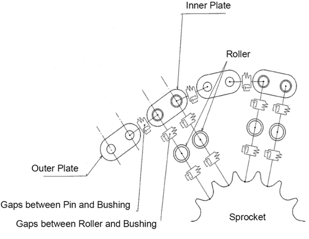
Gap Link | Enter the gap link value. The gap between pin and bushing. |
Roller Stiffness | |
Translational (X,Y) | |
Stiffness | Enter the stiffness of the chain roller in the x direction (along the chain) and Y direction. The stiffness is in force units/length units. ■K1 is in force units/length units ■K2 is in force units/length units**2 ■K3 is in force units/length units**3 ■K4 is in force units/length units**4 ■K5 is in force units/length units**5 |
Damping | Enter the damping coefficient of the chain roller in the x direction (along the chain) and Y direction. The damping is in force units * time units/length units. |
Rotational (Z) | |
Damping | Enter the rotational damping coefficient of the chain roller around the z-axis; that is, the center axes of the rollers. The damping is in force units * length units * time units/angle units. |
Gap roller | Enter the gap roller value. The gap between roller and bushing. |
Geometry settings | Chain Link ■None No link graphics will be present only rollers. Animations may perform faster with this option. ■Simple Simple link graphic is used. Animations may perform faster compared to using detailed link graphic. ■Detailed Fully detailed link graphic. Force graphics ■Enable Force graphic vectors will be displayed while animating results. ■Disable Force graphic vectors will not be displayed while animating results. Link to Guide Select one of the following to specify where the link to guide contact should occur. Either at the connection between links or at the back of a link: ■Connection Contact point at the connection point between links. ■Link Back Contact point at the back of a link. |