Create Cam System
Machinery → Create Cam System
For the option | Do the following |
|---|---|
Type | |
System Name | Enter the system name. The name of the Cam system that is being created is auto generated. The user may edit it if required. |
Cam Profile Input Type | ■Existing/Create - Select an existing cam profile (for example, created from the cam profile wizard) or create a new cam profile (from the cam profile wizard) to be used here. ■Import - Select if the cam profile exists as data points in a .csv file. |
Follower Name | Unique name that refers the Follower. It will be automatically generated by the wizard but the user may edit it if required. |
If you selected Cam Profile Input type as Import, the following options displayed: | |
Cam Profile Name | Unique name that refers the cam profile. It will be automatically generated by the wizard but the user may edit it if required. |
Methods | |
Follower (1), (2) | |
No of Followers | Select one or Two based on the number of followers that the system should contain. |
If you selected No.Of Followers as Two, the following option displayed: | |
Angular Offset | Enter the angular offset value (00 to 3600) between the first and the second follower. The first follower will be placed at the position corresponding to time/angle equal to 0. The second follower will be placed X degree from first follower in the counter- clockwise direction. |
Cam-Follower Connection | ■Constraint - follower will be connected to the cam with a constraint (point-to-curve constraint for knife-edged followers, curve-to-curve for all other follower types). ■Contact - follower and cam interface is modeled as a 2D or 3D contact force. |
Specifications-Cam (Cam Profile Input Type = Existing/Create) | |
Cam Profile Name | Select the existing cam profile name using the options from right click mouse button or Create a new cam profile by clicking the "Create Cam Profile" icon in the right side. |
Cam Shape | The shape of the cam (disk, single sided grooved or cylindrical). This will be automatically set on the type of selected cam profile. |
Center Point Location | Location will be loaded based on the selected cam profile. |
Orientation | Enter the initial orientation of the cam relative to the global coordinate system. |
Specifications-Cam (Cam Profile Input Type = Import) | |
External File | ■Browse for and specify the .csv file containing the cam profile points. ■Select the type of coordinate system used in the file from the options provided: Cartesian or Polar 1. The .csv points should be based on cam center. 2. The first point of the cam profile will be the minimum radius point (cam and follower contact point without considering offset). 3. Consecutive points given in clockwise order. For examples of valid formats for each see “<install_dir>/amachinery/examples/cam”. |
Shape | Specify the cam shape as either Disk, Single Sided Grooved or Cylindrical(Barrel). |
If you selected Shape as Disk, the following options displayed: | |
Minimum Radius | Enter the minimum radius of the cam (also known as base radius). |
Center Point Location | Location will be loaded based on the selected cam profile. |
Cam Thickness | This defines the thickness of the cam part. |
Orientation | Enter the initial orientation of the cam relative to the global coordinate system. |
If you selected Shape as Cylindrical(Barrel) the following options displayed: | |
Radius | Enter the cam radius. |
Offset Along Cam Axis | Enter the offset between initial position of the follower and the specified end of the cylinder. 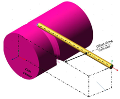 |
Groove Width | Enter the groove width. |
Groove Depth | Enter the groove depth. |
Center Point Location | Location will be loaded based on the selected cam profile. |
Cam Length | This defines the length of the cam part. |
Orientation | Enter the initial orientation of the cam relative to the global coordinate system. |
If you selected Shape as Single Sided Grooved the following options displayed: | |
Radius | Enter the cam radius. |
Offset from Cam center | Enter the offset between Cam center and the initial position of the follower. 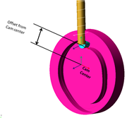 |
Groove Width | Enter the groove width. |
Groove Depth | Enter the groove depth. |
Center Point Location | Location will be loaded based on the selected cam profile. |
Cam Thickness | This defines the thickness of the cam part. |
Orientation | Enter the initial orientation of the cam relative to the global coordinate system. |
Connections-Cam | |
Mount Style | Select the mount style from the list. ■Joint ■Bushing ■None |
Joint Type | Select the joint type from the list. If bushing is selected Joint Type will be hidden. ■Revolute ■Fixed |
Mount Part | Select the type of mount part from the list. ■Rigid Body ■Flexible Body |
Rigid/Flexible Body Name | Enter the name of the body to which the cam should be connected. |
If you selected Mount Style as Bushing the following options displayed: | |
Stiffness Values | Specify the busing parameters: ■Radial Kx - radial stiffness (translational along both local x,y axes) ■Axial Kz - axial stiffness (translational along axis of rotation, local z axis) ■Bending KTx - bending stiffness (rotational about both local x,y axes) ■Torsional KTz - torsional stiffness (rotational about axis of rotation) ■Damping Ratio - multiplier on each stiffness coefficient to determine damping coefficients. |
Specifications-Follower | |
Follower (1), (2) Follower specifications are displayed ( most of them in a non-editable format) in this page of the wizard: | |
Follower Geometry | Knife Edged, Circular, Curve Faced, Flat Faced. |
Follower Motion Type | Translation or Pivot. |
Follower Arrangement | Inline or Offset. |
Offset Distance | The offset between the Cam axis and the follower axis. |
Pivot offset from Cam center | ■X Offset - The offset of Pivot point along X axis ■Y Offset - The offset of Pivot point along Y axis 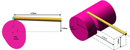 |
Second follower Pivot Location | ■Enter the pivot location of the second follower [optional]. The Pivot point of the second follower is calculated automatically based on the pivot point of the first follower such that the arm length is maintained. Enter/select a location to alter this calculated value. |
Dimensions-Follower | |
Follower (1), (2) 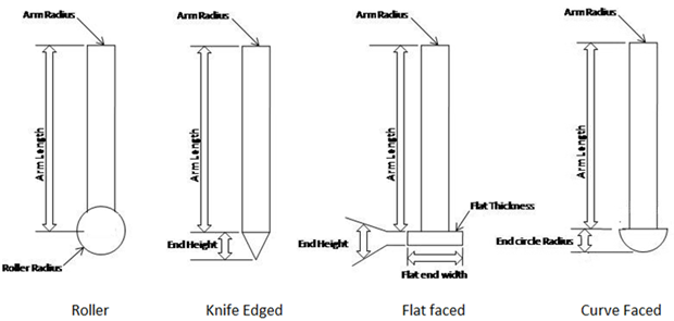 | |
Arm Length | Enter the follower arm length. |
Arm Radius | Enter the follower arm radius. |
End Circle Radius | Enter the radius of circular end of follower Applicable only to Circular end follower and curved end follower. |
Torsional Damping Co-efficient | Enter the damping co-efficient value provided to the rotation of the end roller. Applicable only to Circular end follower. |
End Height | Enter the follower end height Applicable to Knife edged and Flat faced followers. |
Flat end width | Enter the width of the flat end of the follower. Applicable to Flat faced followers. |
Flat Thickness | Enter the thickness of the flat end of the follower. Applicable to Flat faced followers. |
End Curve Radius | Enter the radius of circular end of follower. Applicable only to curved end followers. The curve is obtained by sweeping the entered radius for 180 degree with follower arm axis as center. |
Follower Tilt-angle | Enter the angular tilt value between follower axis and Cam Y-axis. The value may be between +45deg and - 45deg. The sign convention is counter-clockwise positive about the cam's z-axis (axis of positive rotation defined as "orientation" in previous pages of the wizard) per the right-hand rule. 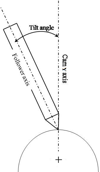 Note: This option is applicable only to Translation Motion of Disk and Single sided Grooved Cam. |
Connections-Follower | |
Follower (1), (2) | |
Mount Style | Select the mount style from the list. ■Joint ■Bushing ■None |
Joint Type | Select the joint type from the list. If bushing is selected Joint Type will be hidden. ■Translational - Select this to establish Translational joint between follower and follower attach part. Applicable only if follower motion type = Translational ■Revolute - Select this to establish Revolute joint between follower and follower attach part. Applicable only if follower motion type = Pivotal ■Fixed - Select this to establish Fixed joint between follower and follower attach part. |
Mount Part | Select the mount part from the list. ■Rigid Body ■Flexible Body |
Rigid/Flexible Body Name | Enter the name of the body to which the follower should be connected. |
If you selected Mount Style as Bushing the following options displayed: | |
Bushing Properties | Specify the busing parameters: ■Radial Kx - radial stiffness (translational along both local x,y axes) ■Axial Kz - axial stiffness (translational along axis of rotation, local z axis) ■Bending KTx - bending stiffness (rotational about both local x,y axes) ■Torsional KTz - torsional stiffness (rotational about axis of rotation) ■Damping Ratio - multiplier on each stiffness coefficient to determine damping coefficients |
Contacts | |
If you selected Cam-Follower Connection as Contact the following options displayed: | |
Normal Force | |
Impact Parameters | ■Stiffness Enter the stiffness coefficient of the cam-to-follower contact. ■Force Exponent Specify the stiffness exponent of the cam-to-follower contact force formulation. The stiffness exponent is typically larger than 1. ■Damping Specify the damping coefficient of the cam-to-follower contact force formulation. The damping is in force units * time units/length units. ■Penetration Depth Enter a value to define the penetration at which Adams Solver turns on full damping. Adams Solver uses a cubic STEP function to increase the damping coefficient from zero, at zero penetration, to full damping when the penetration reaches the damping penetration. A reasonable value for this parameter is 0.01 mm. For more information, see the IMPACT function in the Adams Solver online help. |
Friction Force | ■Coloumb Currently only a Coulomb friction model is supported, It uses a "double-step" model for the friction coefficient vs. relative velocity curve. The friction coefficient increases from 0 to the static coefficient as velocity increases from 0 the stiction transition velocity, then the friction coefficient decreases from the static coefficient to the dynamic coefficient as velocity increases from the stiction transition velocity to the friction transition velocity. ■None No friction is created between cam-follower |
Coulomb Friction Parameters | ■Static Coefficient Specify the coefficient of friction at a contact point when the slip velocity is smaller than the value for Static Transition Vel. For information on material types versus commonly used values of the coefficient of static friction, see Material Contact Properties Table. Excessively large values of Static Coefficient can cause integration difficulties. Range: Static Coefficient ≥ 0 ■Dynamic Coefficient Specify the coefficient of friction at a contact point when the slip velocity is larger than the value for Friction Transition Vel. For information on material types versus commonly used values of the coefficientof the dynamic coefficient of friction, see Material Contact Properties Table. Excessively large values of Dynamic Coefficient can cause integration difficulties. Range: 0 ≤ Dynamic Coefficient ≤ Static Coefficient ■Stiction Transition Velocity Enter the static transition velocity. The figure below shows how the coefficient of friction varies with slip velocity at a typical contact point. 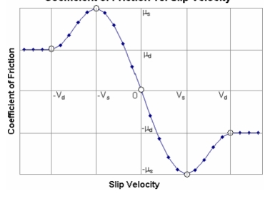 |
In the figure: Vs, the slip velocity at which the coefficient friction achieves a maximum value of μs, is denoted as STICTION_TRANSITION_VELOCITY. μs is the coefficient of static friction. μd is the coefficient of dynamic friction. For more on friction in contacts, see Contact Friction Force Calculation. In addition, read the information for the CONTACT statement in the Adams Solver online help. Range: 0 < Static Transition Vel. ≤ Friction Transition Vel. ■Friction Transition Velocity Enter the friction transition velocity. Adams Solver gradually transitions the coefficient of friction from the value for Static Coefficent to the value for Dynamic Coefficient as the slip velocity at the contact point increases. When the slip velocity is equal to the value specified for Friction Transition Vel., the effective coefficient of friction is set to Dynamic Coefficient. For more on friction in contacts, see Contact Friction Force Calculation. In addition, read the information for the CONTACT statement in the Adams Solver online help. Note: Small values for this option cause the integrator difficulties. You should specify this value as: Friction Transition Vel. ≥ 5* ERROR Error is the integration error used for the solution. Its default value is 1E-3. ■Range: Friction Transition Vel. ≥ Static Transition Vel. > 0 | |
Coloumb Friction | Specify whether the friction effects are to be included at run time: ■On ■Off ■Dynamics Only |
Loadings-Follower | |
Follower (1), (2) | |
Follower Loading | ■Spring Load A spring-damper force is provided between follower and attachment part ■None No force component is provided between follower and attachment part |
If you selected Spring Load, the following options displayed: The following force function defines the spring load: F = - Stiffness * (dm - Length at preload) - Damping * Vr + Preload dm = Displacement Vr = Velocity Or F = - Stiffness * (az - angle at preload) - Damping * Wz + Preload Where az = Angular Displacement Wz = Angular Velocity | |
Stiffness Coefficient | Enter the stiffness coefficient of the force component. |
Damping coefficient | Enter the damping coefficient of the force component. |
Length at Preload | Enter the free length. Applicable only to Follower Motion type = Translational. |
Angle at Preload | Enter the angle value for preload of torsion spring. Applicable only to Follower Motion type = Pivotal. |
Preload | Enter the preload value. |
Material Properties By default, Adams View calculates the mass and inertia for a rigid body part based on the part's geometry and material type. The geometry defines the volume and the material type defines the density. The default material type for rigid bodies is steel. You can change the material type used to calculate mass and inertia or simply specify the density of the part. If you do not want Adams View to calculate mass and inertia using a part's geometry, material type, or density, you can enter your own mass and moments of inertia. It is possible to assign zero mass to a part whose six Degrees of freedom you constrain with respect to parts that do have mass. You should not assign a part zero mass, however. Any part that has zero mass and translational degrees of freedom can causes simulation failure (since a = F/m). Therefore, we recommend that you assign finite masses and inertias to all parts. In addition, a part without mass cannot have mass moments of inertia. ■Learn about Methods for Calculating Mass Properties. | |
CAM/ Follower Arm/Follower End | |
Define Mass By | ■User Input If you do not want Adams View to calculate mass and inertia using a part's geometry, material type, or density, you can enter your own mass and moments of inertia. ■Geometry and Density You can change the material type used to calculate mass and inertia or simply specify the density of the part. ■Geometry and Material Type The geometry defines the volume and the material type defines the density. |
If you select User Input, the following options will be displayed: | |
Mass | Enter the mass of the Cam/Follower Arm/Follower End part. |
Inertia | |
Ixx/Iyy/Izz | Enter the values that define the principal mass-inertia components of the Cam/Follower Arm/Follower End part. |
Ixy/Izx/Iyz | Enter the values that define the deviational (cross-product) mass-inertia components of the Cam/Follower Arm/Follower End part. |
If you select Geometry and Density, the following options will be displayed: | |
Density | Enter the density value. |
If Geometry and Material Type option selected, the following options will be displayed: | |
Material Type | Enter the material type to be used inertia calculation. |