Modifying Part Properties
Each moving part in Adams View can have the following properties in addition to having geometry:
■Location and name
■Mass and inertia
■Initial velocities
■Initial location and orientation
Adams View automatically calculates the total mass of the part and its inertia based on the part's volume and density. It also automatically calculates the initial velocity and position for the part based on any other initial conditions and connections in your model. You can set how you want Adams View to calculate these properties as well as define these properties yourself as explained in the next sections.
Note: | You can also modify part properties using the Table Editor. Learn about Editing Objects Using the Table Editor |
Modifying Part Name and Location
While you are modifying a part, you can change its name and set its location relative to another location. You can also set a rigid body so it is a planar part.
To modify part name and location:
1. If you haven't already done so, display the Modify Body dialog box as explained in Accessing Modify Dialog Boxes.
2. Set Category to Name and Position.
3. Change the name of the geometry, if desired, and assign a unique ID number to the body, if appropriate.
4. In the Location text box, enter the location of the rigid body. Adams View applies your location coordinates in the coordinate system in the Relative To text box.
5. Specify either of three orientation methods and their appropriate value:
6. In the Relative To text box, enter the reference frame relative to which the location and orientation entries are defined. Leave blank or enter model name to use the global coordinate system.
8. Select OK.
Modifying Mass and Inertia for Rigid Bodies
By default, Adams View calculates the mass and inertia for a rigid body part based on the part's geometry and material type. The geometry defines the volume and the material type defines the density. The default material type for rigid bodies is steel. (Note that any geometry that you deactivate will not be included in mass calculations.)
You can change the material type used to calculate mass and inertia or simply specify the density of the part. If you do not want Adams View to calculate mass and inertia using a part's geometry, material type, or density, you can enter your own mass and moments of inertia. Learn about Setting Up Material Types.
It is possible to assign zero mass to a part whose six degrees of motion you constrain with respect to parts that do have mass. You should not assign a part zero mass, however. Any part that has zero mass and translation degrees of freedom can causes simulation failure (since a = F/m). Therefore, we recommend that you assign finite masses and inertias to all parts. In addition, a part without mass cannot have mass moments of inertia.
Methods for Calculating Mass Properties
Adams View uses two different methods to calculate mass properties. If you modify the number of sides Adams View uses to define a part’s geometry, such as cylinder, frustum, or torus, Adams View may use a different method to calculate the part’s mass properties depending on the number of sides, as explained below.
■If the number of sides is greater than or equal to the default number of sides (usually 20), Adams View calculates the mass using an analytical equation for the geometry volume. It uses a true solid that the name of the part indicates.
■If the number of sides is less than the default, Adams View uses a prismatic solid, which you actually see on the screen, to calculate mass properties. This method is slower but gives more accurate results. For example, if you change the number of sides of a cylinder from 20 to 3, the geometry on the screen is of a triangular solid. This solid’s mass properties will be significantly different that a cylinder’s mass properties.
To modify mass and inertia:
1. If you haven't already done so, display the Modify Rigid Body dialog box as explained in Accessing Modify Dialog Boxes.
2. Set Category to Mass Properties.
3. Set Define Mass By to how you want Adams View to calculate mass and inertia, enter the appropriate values, and select OK. Learn About Entering Mass Moments of Inertia.
From the pull-down menu, select: | And enter: |
|---|---|
Geometry and Material Type | In the Material Type text box, the type of material for the part. Adams View displays the material's composition below the text box. Adams View uses the density associated with the material type and volume of the geometry of the part to calculate the part's mass and inertia. To select a material type from the Database Navigator or create a new material type, right-click the text box, and then select the appropriate command. Learn about Setting Up Material Types. |
Geometry and Density | In the Density text box, enter the density of the part. Adams View uses the part's density and the volume of the geometry to calculate its mass and inertia. |
User Input | Mass - In the Mass text box, enter the mass of the part. Moments of inertia - Enter the mass moments of inertia. Center-of-mass marker - In the Center of Mass Marker text box, enter the marker that is to be used to define the center-of-mass (CM) for the part. Inertia marker - In the Inertia Reference Marker text box, specify the marker that defines the axes for the inertia properties. If you do not enter an inertia marker, Adams View uses the part CM marker for inertia properties. |
About Entering Mass Moments of Inertia
In the Rigid Body Modify dialog box, you can enter either just the principal mass moments of inertia (Ixx, Iyy, Izz) or enter the cross products of inertia (Ixy, Ixz, and Iyz). You will want to enter the mass products of inertia if the inertia marker or center-of-mass (CM) marker is not at the center of mass of the part and not aligned with the principal axes.
To enter cross-products of inertia, select the check box Off-Diagonal Terms. The Modify Rigid Body dialog box displays text boxes for entering the cross products of inertia.
The inertia matrix is defined as follows:
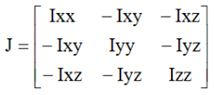
The inertia matrix is a symmetrical, positive-definite matrix. You compute the individual terms in the matrix as follows:
In the above formula, x, y, and z are the components of the displacement of an infinitesimal mass particle of mass dm, measured from the origin of the inertia marker in the coordinate system of the inertia marker. The integral is performed over the entire mass of the body. If you do not specify the inertia marker, Adams View uses the CM marker. In that case, you compute these quantities about the origin of the CM marker in the coordinate system of the CM marker.
Note: | Adams View defines Ixy, Ixz, and Iyz as positive integrals, as shown. Some references define these terms as the negative of these integrals. You should be sure to compute these values as shown above. |
Displaying Calculated Mass Moments of Inertia
If you select to have Adams View calculate the mass moments of inertia of a part based on the part's geometry and material type or density, you can view the mass-inertia tensor matrix that Adams View calculates.
To view the matrix:
■In the Modify Rigid Body dialog box, select Show calculated inertia.
Modifying Initial Velocities
You can specify initial velocities for parts. Adams View uses the initial velocity during the Initial conditions simulation, which it runs before it runs a Simulation of your model.
You can specify translational and angular velocities for rigid bodies and flexible bodies and only translational velocity for point masses.
■Translational velocity defines the time rate of change of a part's center of mass with respect to ground or another marker in your model. You can specify translational velocity for each vector component of the marker.
■Angular velocity defines the time rate of change of a part's rotational position with respect to the CM marker of the part or another marker in your model. You can specify angular velocity for each vector component of the marker.
If you specify initial velocities, Adams View uses them as the initial velocity of the part during initial conditions simulations regardless of any other forces acting on the part. You can also leave some or all of the velocities unset. Leaving a velocity unset lets Adams View calculate the velocity of the part during an assemble operation depending on the other forces and constraints acting on the part. Note that it is not the same as setting the initial velocity to zero. Setting an initial velocity to zero means that the part will not be moving in the specified direction when the simulation starts regardless of any forces and constraints acting upon it.
To modify initial velocities:
1. If the Modify Body or Create/Modify Point Mass dialog box is not already displayed, display it as explained in Accessing Modify Dialog Boxes.
2. Set Category to Velocity Initial Conditions.
The dialog box changes so you can enter translational and angular velocity. If you selected Velocity Initial Conditions from the Modify Point Mass dialog box, only the options for setting translational velocity are available.
3. Set the translational and angular velocity as explained in the table below, and then select Apply.
To: | Do the following: |
|---|---|
Select the coordinate system along or about whose axes the translational or angular velocity vector components will be specified. | Select the following: For translational velocity, select Ground or select Marker and enter a marker in your model in the text box that appears. For angular velocity, select Part CM to select the part's center-of-mass (CM) marker or select Marker and enter a marker in your model. |
Set the velocity along or about an axis | Select the axes along or about which you want to define velocity and enter the velocity in the text box that appears next to the axes check boxes. Remember, leaving a velocity unset lets Adams View calculate the velocity of the part during an initial conditions simulation depending on the other forces and constraints acting on the part. It is not the same as setting the initial velocity to zero. |
Modifying Initial Location and Orientation
In addition to specifying initial velocities, you can also control the initial position for a part’s location and orientation. You should specify the initial position when you do not want Adams View to reposition the part. Adams Solver uses the initial position during an Initial conditions simulation, which it runs before it runs a Simulation of your model.
You can control initial locations and orientations for rigid bodies and Flexible bodies and only initial locations for Point masses.
■Location fixes any of the current translational coordinates (x, y, or z) of the part as the initial location.
■Orientation fixes any of the current body-fixed 313 rotational coordinates (psi, theta, or phi angles) as the initial orientation. These rotation angles are those associated with a body-fixed 313 rotation sequence regardless of which sequence you set as the default for the modeling database. (Learn about Rotation Sequences.)
If Adams Solver has to alter part positions to obtain consistent initial conditions during an initial conditions simulation, it does not vary the coordinates you specify, unless it must vary them to satisfy the initial conditions you specify for a joint or a motion.
If you fix the initial positions of too many parts, the initial conditions simulation can fail. Use initial positions sparingly.
To modify initial position and orientation:
2. Set Category to Position Initial Conditions.
The dialog box displays options for setting position initial conditions. If you selected Position ICs from the Modify Point Mass dialog box, only options for setting location conditions are available.
3. Select the coordinates or angles that you want fixed during initial conditions simulation as explained in the Modify Body - Position Initial Conditions and select Apply.