Advanced 3D Contact Gear
Within the Adams Machinery Gear module the Advanced 3D Contact method option can represent gear tooth flexibility for cylindrical gears (straight and helical, internal and external). This is distinct from other Adams Machinery Gear methods where the gears are modeled as rigid parts with a compliance between them. The Advanced 3D Contact method option allows one to define the gear part geometry and material properties, from which a finite element model (FEM) is created and solved in the background to define tooth compliance. No knowledge or installation of finite element analysis (FEA) tools is required. The meshing and FEA are fully automated and leverage Nastran technology embedded directly in Adams.
Note: | This background FEA work generates temporary files in your working directory which can consume significant disk space (on the order of 1-50 GB). As the size of the FE models increase so will these temporary files; see the Mesh Properties section of the dialog box help for the Adams Machinery Gear Advanced 3D Contact method for more detail. Gear tooth contact geometry is based on ISO 21771:2007. |
Preprocessing, simulation and post processing essentially follows the sequence as below:
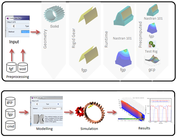
Figure 14 Modeling Process
From the basis of this FEA there are three options to define the contact behavior of the gear pair during the Adams analysis all of which represent the contact between gears in the Adams model as a GFORCE:
■The Run Time option computes the contact behavior of the gears during the analysis and is the most accurate
■The Pre Computed option runs a setup analysis to predict contact behavior which saves time during the actual system simulation often with little trade-off in result accuracy
■The Rigid option simplifies things further by treating the gear teeth rigidly. This, however, is distinct from the pre-existing rigid-body 3D Contact method. The Advanced 3D Contact method's "Rigid" contact option frequently results in smoother forces because the contact detection is not based on traditional tessellation techniques but rather the FEM-based fine meshes. Also, there are more tooth and gear modification options available through the Advanced 3D Contact method including commonly applied micro-geometry modifications.
The flexible tooth options here provide superior accuracy compared to using an Adams Flex representation of the gears. Adams Flex uses the modal superposition method, which assumes that the part's deformation can be captured by superimposing normal mode shapes. But in the case of gears, most of the deformation takes places in the teeth themselves, which is difficult to capture in the mode shapes.
Advanced 3D Contact improves upon the preexisting Adams Machinery Gear methods in several ways ultimately allowing for the accurate calculation of dynamic gear meshing forces including microgeometry, tooth deformation and instantaneous misalignment. These capabilities allow users to evaluate meshing-order transmission error and system excitation, along with potential interactions of this behavior with case, shaft and bearing motions. Users may evaluate the tooth contact pressures in high-load conditions and identify if the microgeometry used is sufficient for addressing potential stress concentrations. In addition, the enhanced tooth accuracy will provide improved dynamic predictions for rattle, whine and other transient operating conditions.
Gear Specification Data Persistency
As with all the other Adams Machinery components and methods exposed with Adams View, all of the inputs can be saved and stored in a wizard file.
Using Legacy FGF file from GearAT toolkit
Gear profile data can be migrated from GearAT toolkit by using .FGF (Figure 15) file by changing the UDE definition in the .FGF file from '.gear_at.udes.gear_at_element' to ‘.amachinery.udes.ac_am_adv_3d_gear_element'.
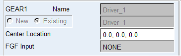
Figure 15 FGF use
Post Processing
All standard requests are available for rigid gear and runtime gear force modeling option, however for PreComputed contact modeling, the number of results is limited.
Some of the results are reported in the so-called contact coordinate system (CCS). Each gear stage has such coordinate system as shown in. The origin of the CCS is located at the reference marker of wheel 1. The z-axis of the CCS is identical with the z-axis of wheel 1. The x-axis and y-axis of the CCS lie in the plane normal to the z-axis at the center of wheel_1. The projection of the vector from wheel center 1 to wheel center 2 on the normal plane gives the y-axis of the CCS. The x-axis of the CCS follows from the right hand rule. It is assumed, that no more than 5 teeth are in contact.
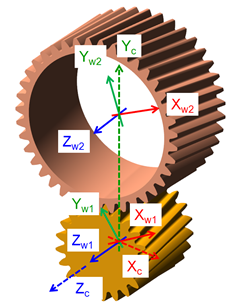
Figure 16 Contact Coordinate System
Standard Requests:
Output request for option Standard:
■*_contact tooth
■*_distance_and_misalignment
■*_maximum_penetration
■*_total_contact_force_and_torque_on_wheel_1
■*_total_contact_force_and_torque_on_wheel_2
■*_Transition_Damping
■*_Transmission_Error
Output request for option Detail wheel 1:
■*_contact_force_and_torque_on_wheel_1
■*_friction_force_and_torque_on_wheel_1
■*_hydrodynamic_damping_force_torque_wheel_1
■*_structural_damping_force_and_torque_on_wheel_1
Output request for option Enhanced:*_Tooth Forces
■*_Hydrodamping Force per Tooth
■*_max_contact_pressure
■*_KF_beta
■*_KH_beta
■*_max_sliding_velocity
■*_max_squeeze_velocity
■*_minimum_gap
The request *_contact tooth contains following results:
■contact_tooth_wheel_1 (see Figure 17)
■contact_tooth_wheel_2 (see Figure 17)
■friction power loss
■structural power loss
■hydrodynamic power loss
■total power loss
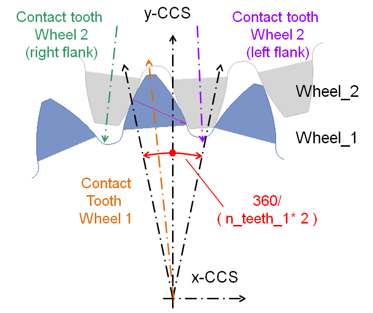
Figure 17 Definition of contact tooth
The result *_distance_and_misalignment gives the position and the rotation around the x- and y-axis of wheel_2 against wheel_1 in the CCS.
Result *_maximum_penetration helps to evaluate the selected contact stiffness for rigid body contact. In case of a flexible tooth, only a small penetration should be reported under normal operating conditions. The tooth_0 is the tooth in the middle of the rim of wheel 1 with the smallest deviation to the yz-plane of the CCS. The relative teeth numbers -2 to +2 follow right hand side rule if the thumb points in wheel_1 z axis direction (Figure 17).
The resulting forces and torques in the CCS on wheel 1 are given by *_total_contact_force_and_torque_on_wheel_1. The corresponding forces and torques on wheel 2 can be viewed under *_total_contact_force_and_torque_on_wheel_2. The resulting forces include all effects from contact, damping and friction. Results in request Transition Damping should help to set the damping ratio and end time for the damping. Result Transmission_Error calculates the absolute difference between ideal and present gear ration in the gear pair, it is calculated from equation:
TE = phi_w2 * (N2 / N1) - phi_w1
where:
■Phi means rotation angle.
Following results enable to quantify the different contributions to the resulting force and torque.
■*_contact_force_and_torque_on_wheel_1,
■*_friction_force_and_torque_on_wheel_1,
■*_hydrodynamic_damping_force_and_torque_on_wheel_1
■*_structural_damping_force_and_torque_on_wheel_1
Design engineers can review the enhanced requests collecting: resulting contact force and hydrodynamic force on individual teeth under *_Tooth_Forces and *_Hydrodamping Force per Tooth, Max Contact pressure on individual teeth, relative velocities in contact and KF_beta and KH_beta coefficients.
For Precomputed method following list of results available, while most of them are identical with already discussed results:
■gear_wheel_1_wheel_2_total_contact_force_and_torque_on_wheel_1
■gear_wheel_1_wheel_2_Transition_Damping
■gear_wheel_1_wheel_2_contact_force_and_torque_on_wheel_1
■gear_wheel_1_wheel_2_friction_force_and_torque_on_wheel_1
■gear_wheel_1_wheel_2_hydrodynamic_damping_force_torque_wheel_1
■gear_wheel_1_wheel_2_structural_damping_force_and_torque_on_wheel_1
■gear_wheel_1_wheel_2_Tooth Forces
■gear_wheel_1_wheel_2_max_contact_pressure
■gear_wheel_1_wheel_2_max_sliding_velocity
■gear_wheel_1_wheel_2_Displacements_and_Rotations
■gear_wheel_1_wheel_2_Kinematic
*_Displacements_and_Rotations request set comprises in first 5 results normalized translational and rotational displacements and the 6th component shows the loading or normalized perturbation. This request informs the user if the model still operates in valid range of generated data stored in GCP file.
ITY__ITY_max - shaft axes distance perturbation, allowed range < -1 , +1 >
ITZ__ITZ_max - gears axial distance perturbation, allowed range < -1 , +1 >
IRX__IRX_max - lateral misalignment perturbation, allowed range < -1 , +1 >
IRY__IRY_max - radial misalignment perturbation, allowed range < -1 , +1 >
IRZ__IRZ_max - rotational position of wheel 1, allowed range < -0.5 , +0.5 >
Within a pitch
value = 0.0: neutral position
value = -0.5: starting position
value = 0.5: ending position
IPERT__IPERT_max Z axis rotational perturbation, allowed range < -1 , +1 >
*_Kinematic request set comprises kinematical quantities which are involved in the calculation of hydrodynamic damping acting between the contacting surfaces of mating teeth of a gear pair.
gear_gap - gap between teeth along pressure line
gear_gap > 0: clearance
gear_gap < 0: penetration
squeeze velocity - component of profiles relative velocity along pressure line
omega_w1 - angular velocity of wheel 1
omega_w2 - angular velocity of wheel 2
PlusMinus - indicates plus/left or minus/right flank is in contact
Other available requests are identical with Runtime gear force requests.
Simulation Settings
The settings for the performance of the solver are usually dependent on the model. You need to validate, if subsequent comments are applicable to your model:
■In most dynamic simulations, the C++ Solver with the HHT integrator seems to offer the highest performance and stability with the default error tolerance of 1.0e-5. Tighter error tolerance should not cause an important increase in CPU-time.
■The GSTIF/I3 integrator delivers good results, but may require limiting HMAX and/or more patterns. Limiting HMAX may also be a good practice for the HHT Solver.
■A too small number of contact planes may show some numerical noise. A larger number of contact planes is suggested for helical gears. A too large number of contact planes increases CPU-time without substantial increase of result quality.
■Unrealistic contact stiffness for the rigid body contact should be avoided. High numerical stiff leads generally to noisy results and in consequence longer CPU-times. It has to be stated here, that the integrators of Adams are generally efficient and robust.
■An unrealistic high hydrodynamic damping forces the integrator to take small time steps and lead to inaccurate results, as the damping force is dominating the load transfer.
Licensing
In addition to an Adams Machinery Gear license (or the Adams Machinery bundle license), the Advanced 3D Contact method requires the Adams ViewFlex license. This provides access to the finite element meshing and calculation technology used in the pre-processing setup unique to the Advanced 3D Contact method. The ViewFlex license is consumed only while pre-processing in Adams View, Adams Car or Adams Driveline. It is not required necessarily during analysis. During analysis only the Adams Machinery Gear license (or the Adams Machinery bundle license) is necessarily consumed in addition to the usual Adams Solver license. See The specific component-method combinations that consume a license during simulation are listed in the table below: for more details.