Introduction
The Adams Machinery will guide the users in pre-processing via automation of such activities as geometry creation, subsystem connections, and so on. This will also help users in post-processing by providing automated plotting and reporting for commonly desired output channels. It has the GUI-driven wizard-style user interface which prompts users more for physical quantities than virtual ones. It has user friendly in-line help and general useful information about the components and connections and applicability of the modeling fidelity options. The users provided with the options in the GUI to edit, modify and to change the modeling fidelity options by going back to the input wizard.
See the section Adams File Types for more information on Adams Machinery file types.
Starting Adams Machinery
1. On the Start menu, point to Programs, point to Adams 2024.1, and then select Adams View.
2. Select the Adams Machinery from the ribbon tab.
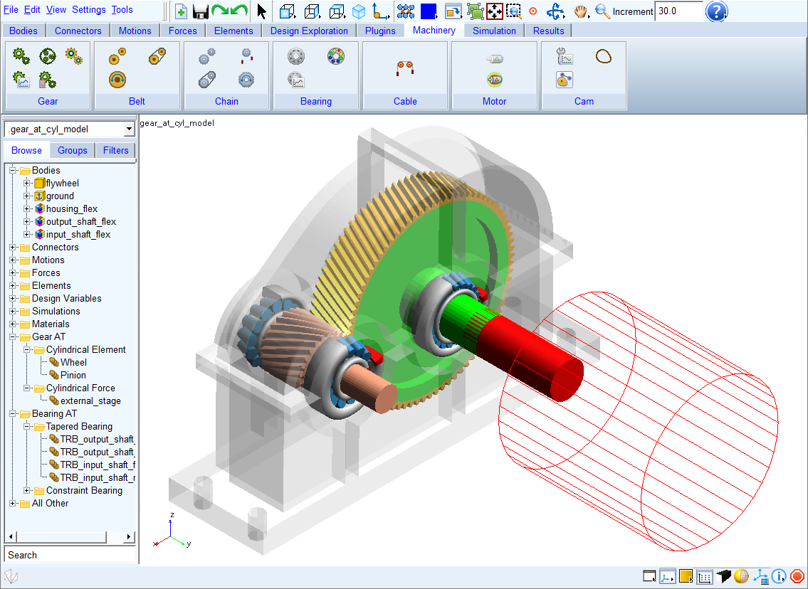
The Adams Machinery tab has 7 subsets as mentioned below.
■Gear
■Belt
■Cam
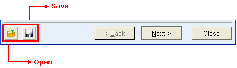
A common interface for each is the use of an input wizard to define the components to be created. By clicking the save button in the lower left of any Adams Machinery input wizard, the current inputs can be saved at any time to a .wzd file whose name and location are determined by the user. The file open button can be used to replace the contents of an Adams Machinery input wizard with those stored in a previously saved .wzd file.
Wizard File Structure
The .wzd file is an xml file consisting of names and values of the GUI elements in the wizards. The file is structured in such a way that all elements under a page are grouped together. Here is an example of a wizard file for the Pulley wizard. Only the first page is shown for simplicity.
<Wizard Name="Create Pulley" >
<Page Name="Type" >
<Element Name="Belt System Name" >
<Value>beltsys_1</Value>
</Element>
<Element Name="Pulley Set Name" >
<Value>pulleyset_1</Value>
</Element>
<Element Name="Type" >
<Value>Poly-V Grooved</Value>
</Element>
</Page>
Below is a brief description of the tags used in the .wzd file.
Tag | Attribute | Description |
|---|---|---|
Wizard | Name | Name of the wizard |
Page | Name | Name of the page |
Element | Name | Name of the GUI widget (field, option_menu, radio_box, slider, and so on.) |
Value | The value of the widget | |
Container | Name | Name of the container |
Container
The 'Container' tag appears inside a 'Page' and is used in cases where there are multiple groups of similar inputs. For example, in a Pulley wizard, if the number of pulleys is 2, both the set of inputs for Pulley1 and Pulley2 are similar. These appear under separate containers in the wizard file as below:
<Page Name="Geometry-Pulleys" >
<Element Name="Number of Pulleys" >
<Value>2</Value>
</Element>
<Container Name="Pulley1" >
<Element Name="Name" >
<Value>p1</Value>
</Element>
<Element Name="Center Location" >
<Value>-500.0, 350.0, 0.0</Value>
</Element>
<Element Name="Width" >
<Value>30</Value>
</Element>
<Element Name="Pitch diameter" >
<Value>75</Value>
</Element>
</Container>
<Container Name="Pulley2" >
<Element Name="Name" >
<Value>p2</Value>
</Element>
<Element Name="Center Location" >
<Value>200.0, 400.0, 0.0</Value>
</Element>
<Element Name="Width" >
<Value>30</Value>
</Element>
<Element Name="Pitch diameter" >
<Value>75</Value>
</Element>
</Container>
As can be observed, "Pulley1" and "Pulley2" are containers under the "Geometry-Pulleys" page.
Note: | Population of wizard contents from .wzd files in this manner is supported only during component creation; the modification process will instead populate the wizard with the current values corresponding to the component which the user selected for modification. |
The specific component-method combinations that consume a license during simulation are listed in the table below:
Adams Machinery Component Method | Adams Machinery Modelling License Consumption | Adams Machinery Run Simulation (Internal/External) License Consumption |
|---|---|---|
Gear | ||
Coupler method pairs | Adams_Machinery_Gear_GUI | X |
Simplified/Detailed method pairs/sets | Adams_Machinery_Gear_GUI | Adams_Machinery_Gear_Solver |
3D Contact method pairs/sets | Adams_Machinery_Gear_GUI | X |
Advanced 3D Contact pairs/sets | Adams_Machinery_Gear_GUI | Adams_Machinery_Gear_Solver |
Note: The Advanced 3D Contact method requires the Adams ViewFlex license. | ||
Gear AT | TK_GearAT_BASE | TK_GearAT_BASE_SOLVER |
Belt | ||
Constraint method | Adams_Machinery_Belt_GUI | X |
2D/3D Links method | Adams_Machinery_Belt_GUI | Adams_Machinery_Belt_Solver |
3D Nonplanar method | Adams_Machinery_Belt_GUI | Adams_Machinery_Belt_Solver |
3D Simplified | Adams_Machinery_Belt_GUI | X |
Chain | ||
Constraint method | Adams_Machinery_Chain_GUI | X |
2D/3D Links method | Adams_Machinery_Chain_GUI | Adams_Machinery_Chain_Solver |
3D Nonplanar method | Adams_Machinery_Chain_GUI | Adams_Machinery_Chain_Solver |
Bearing | ||
Joint method | Adams_Machinery_Bearing_GUI | X |
Compliant method | Adams_Machinery_Bearing_GUI | X |
Detailed method | Adams_Machinery_Bearing_GUI | Adams_Machinery_Bearing_Solver |
Bearing AT | TK_BearingAT_BASE | TK_BearingAT_BASE_SOLVER |
Cable | ||
Simplified method | Adams_Machinery_Cable_GUI | X |
Discretized method (Without Request) | Adams_Machinery_Cable_GUI | X |
Discretized method(With Request) | Adams_Machinery_Cable_GUI | Adams_Machinery_Cable_Solver |
Motor | ||
Curve import | ADAMS_Machinery_Motor | X |
Analytical | ADAMS_Machinery_Motor | X |
External | ADAMS_Machinery_Motor | X |
Emag AT | TK_EM_AT_BASE | TK_EM_AT_SOLVER |
Cam | ||
Motion optimizer | ADAMS_Machinery_Cam | X |
Cam profile derivation | ADAMS_Machinery_Cam | X |
Cam system assembly | ADAMS_Machinery_Cam | X |