Gear AT Fast Preprocessing
The contact algorithm of Gear AT is efficient yet detailed so it is not feasible for simulation of large gear train assemblies over long simulation time. To overcome this limitation there is Gear AT Fast module which employs pre-computed gear contact thus providing high performance gear contact model at the expense of reduced accuracy of contact friction and damping. In addition to that, one cannot visualize contact pattern and is not possible to modify tooth micro geometry using pre-computed gear contact so it has to be settled before. The data of pre-computed gear contact are stored in a look up tables written in the *.wgf (Worm Gear Fast) file. The data are generated by conducting a large set of automatically controlled simulations driven by the built in testrig.
Complete the Gear AT Fast Preprocessing in following steps
Create Testrig for preprocessing
The preprocessing starts with building of gear pair testrig. This process is highly automated and offers the user to create the testrig either from existing model by selecting the Gear Force of existing gear pair or manually by selecting “from_wgp” and followed by entering the names of gear element input files *.wgp, *.wgs
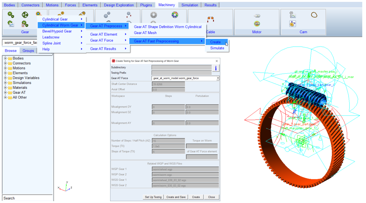
Figure 204 Create testrig for Worm Gear AT Fast preprocesing
Prerequisite for creating the testrig is existence of worm gear property files, *.wgp and *.wgs files. If those files do not exist, you need to create them by following the guidelines in the section Gear AT Mesh. The dialog box for creating the testrig is invoked from Gear AT - Cylindrical Worm Gear - Gear AT Preprocess - Gear AT Fast Preprocessing - Create menu as depicted on Figure 204.
After clicking on the Create or Create and Save button the testrig is created or created and saved, respectively, in Adams View command file in the directory specified in Subdirectory field if entered, otherwise into current working directory. The name of the testrig is Testrig Prefix_Gear AT Force_fast in case it was created from existing Gear AT Force element or Testrig Prefix_from_wgp_fast in case it was created from WGP files.
Once the testrig has been created, you can set it up and simulate to preprocess *.wgf file for Gear AT Fast simulations by either clicking the Set Up Testrig button or by navigating through Gear AT menu.
Set up and simulate testrig
The Simulate dialog box and meaning of all entries are depicted in Figure 205. The Simulate dialog box is invoked from Gear AT - Cylindrical Worm Gear - Gear AT Preprocess - Gear AT Fast Preprocessing - Simulate menu. You can also load previously created test rig by selecting the *.cmd file in the Import input field.
Before the preprocessor is launched, you have to define the workspace of a gear pair. For the sake of clarity, let us define following convention. Let us assume the worm gear is called Gear 1 - red wheel located in the origin of so called Contact Coordinate System (CCS) in Figure 205 and worm is called the Gear 2 - in blue color in Figure 205. All results from Gear Fast preprocessing are reported in CCS reference frame.
There is a minimum required workspace definition to be applied under Calculation Options. Entry Number of Steps / Half Pitch defines number of rotational positions along Gear 1 pitch angle at which the contact is evaluated and it corresponds to the AZ rotation on the Figure 205. The number effectively corresponds to Number of Steps / Half Pitch * 2 + 1 steps, starting in position – half pitch angle and ending in + half pitch angle.
Entry Torque defines maximum torque applied on Gear 2 at every workspace position. The torque is applied in number of steps defined in entry Steps of Torque and corresponds to TX torque. If the preprocessor is executed while keeping all input entries of the Workspace group put to zero, it produces *.wgf file with no radial, axial displacements and no angular misalignment relative movement effects, what can be used for simple concept studies using rigid shafts on rigid supports (kinematic joints).
In order to support full relative motion of gears you have to fill the entries in group Workspace. Displacements are applied symmetrically, relative to the initial position of the Gear 2 in number of Steps, the value of displacement amplitude is entered in the Perturbation column. Misalignment DY corresponds to DY translation of Gear 2 and is applied relative to actual shaft center distance of gears. Misalignment DZ corresponds to DZ translation of Gear 2 and Misalignment AY corresponds to Y rotation of Gear 2. The entries in Steps fields effectively define Step * 2 + 1 total steps starting from – Perturbation and going to + Perturbation for every workspace dimension. Please note that entering non-zero perturbation with zero value of steps will deliver wrong results for gears relative movement.
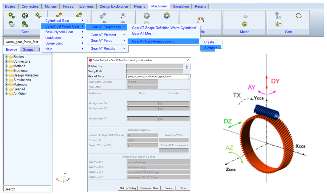
Figure 205 Worm Fast testrig - definition of workspace dimensions
The toggle Show Messages activates/deactivates output of Adams/Solver messages into Adams/View information window. In case of higher number of total iterations it is recommended to not use the Show message option.
Click the Simulate button to automatically launch Gear AT Fast preprocessor. Calculated data are stored in a *.wgf file, in case it was created from existing Gear Force the name is:
Testrig Prefix_Gear AT Force_TORQUE_TX value.wgf
and in case it was created from *.wgp files:
Testrig Prefix_from_wgp_Gear_1_WGP_Gear_2_WGP_TORQUE_TX value.wgf
The preprocessor starts the calculations with so called “Free play study”. In this study the algorithm finds the difference between ideal kinematic position and start of the contact position for every defined workspace dimension combination.
The simulation progress is recorded in a *.log file, which has the same name as the *.wgf file. The *.log file summarizes the estimation of required iteration number to be performed and adequate time estimation for the preprocessing, see Figure 204. Next sections of log file content depict progress and results of free play study and also show current iteration step and details about contact computation at given workspace position.
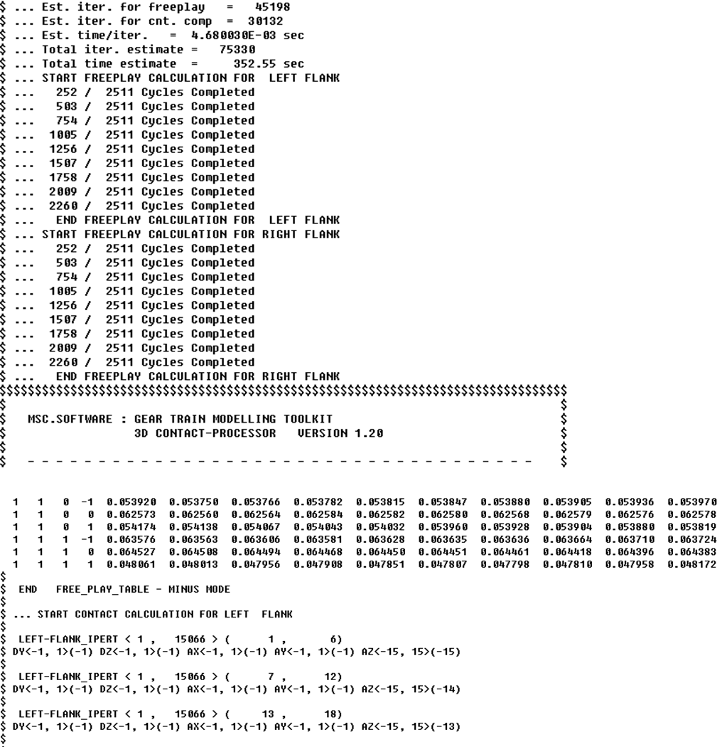
Figure 206 Worm Fast preprocessing - log file content
Modify Gear AT Force
After the preprocessing is completed, the *.wgf file is stored in current working directory. To use it for Gear AT Fast simulation, you have to switch back to your original worm gear model, modify particular Gear AT Force and switch current Modeling Option to Gear AT Fast and browse for *.wgf file you just created (Figure 207).
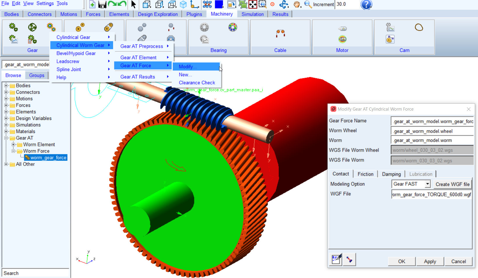
Figure 207 Modify Gear AT force - Worm Fast