Flex Tooth Animation
The Flex Tooth Animation feature is dedicated to visualize contact stress over a contact line due to gear pair engagement and not to provide accurate results of contact stresses since Adams is not dedicated FEA code. It makes use of Adams/Durability plugin which requires separate license feature.
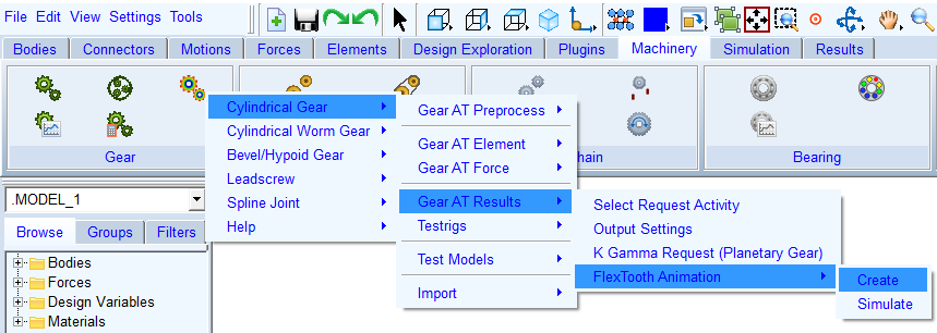
Figure 130 Stress display test rig menu
The Gear AT Flex Tooth Animation test rig application offers the possibility to post-process specific gear pair in a test rig with a single gear pair extracted from the full model. It is provided to visualize tooth stresses over the tooth flank and root surface during contact incident. All data needed to drive and load the flexible gear teeth exists in *.cga file, which can be output from any Adams simulation upon request. The header of the file contains data for settings up the testrig, what allows positioning of the gear wheels based on the full model automatically as well as the start and end time retrieved from previously run Adams simulation. These are inputs specified by the user in stress request dialog box, described in section Output Settings.
Important: | Flex Tooth Animation is currently supported for cylindrical gears only! |
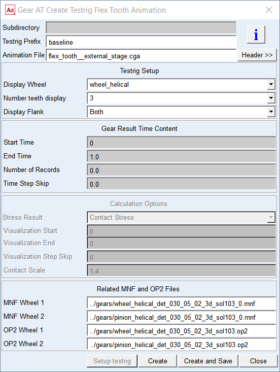
Figure 131 Create Flex Tooth animation testrig
You can display information from CGA file header with the Header button. Specify number of teeth, the flank of interest and gear wheels to be post-processed in the fields of Test rig setup - see Figure 131. An example for 3 teeth, both flanks and both wheels is depicted on Figure 132. The wheels are driven by motion according to data stored in CGA file.
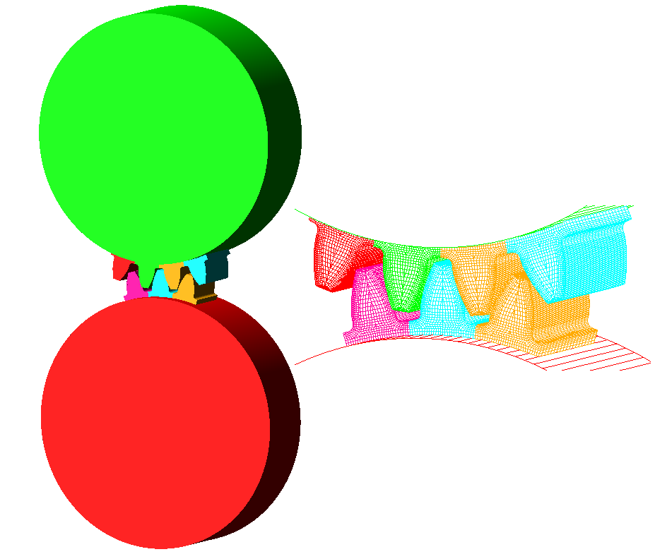
Figure 132 Stress test rig
Normally after the CGA file is selected, the input fields for MNF and OP2 files are automatically filled in. If the algorithm cannot find the files in current working directory, user is prompted to select them manually or create them on the fly.
The post processing settings and the start of quasi static simulation is shown in the dialog box depicted on Figure 133.
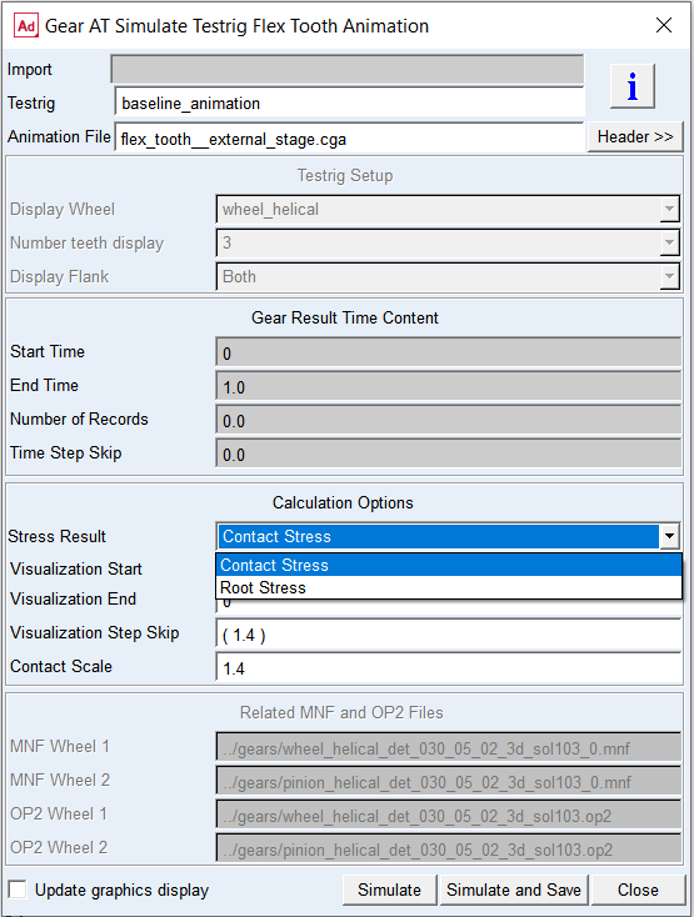
Figure 133 Run Flex Tooth Animation postprocessing
The entries in group CGA Time Content display settings and other conditions the CGA file was created for. The group Calculation Options enables to set the type of stress results to be displayed and the time range of interest within available data records to be post-processed. The Contact stress is available only for Gear 1 and the input is derived from the Hertz contact pressure formula. To visualize approximate contact stresses you need to select following type of contour plot in Adams/Postprocessor:
■Normal-Z Stress on the left flank
■Normal-Y Stress on the right flank
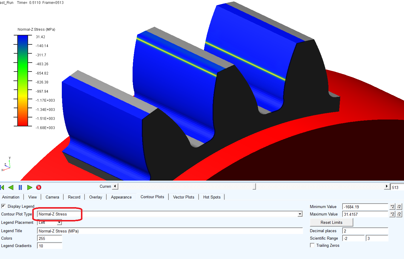
Figure 134 Contact stress visualization
The entry Contact Scale is intended to fine tune the displayed results of contact stress to match maximum contact pressure from the request. Please, note that stress value computed by Adams/Durability is not the stress on the element surface, but in the middle point of the hexa element. The values around 1.4 show good correlation with contact pressures calculated in Gear AT simulation.
The Root stress is available for both wheels and is derived from contact forces. To visualize approximate root stresses you need to select Von Mises Stress contour plot in Adams/Postprocessor.
Adams/Solver allows you to do one or more analyses on the same data set until the STOP command is issued. Therefore the content of CGA file can be composed of results sampled at different output time step. This situation is monitored and indicated in the CGA file header by parameter Step size change = 1. As consequence, visualization will not reflect actual position of gears, however it will be possible to execute postprocessing simulation for the entire time range only, hence parameter fields Visualization Start, Visualization End, Visualization Step Skip are disabled.