Gear AT Advanced Shape Definition
Gear AT Shape Definition allows you to create a file that defines the topology of a gear (both macro and micro geometry). You can define a gear tooth profile either by defining tooth proportions or by simulating manufacturing process using hobbing cutter or pinion cutter tool. Figure 7 shows how to access the tools you need to define your gear geometry.
One cannot import a profile from other gear design software in the current release.
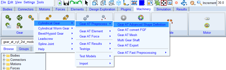
Figure 7 Access to the Gear AT Shape Definition
The Gear AT Shape Definition has following tabs to help you design a gear
■Mass
Main
For the options | Do the following |
|---|---|
Mode (Create, Edit) | In Create mode the user can either enter manually all parameters to input fields or use existing definition file (CGD) to fill up General, Profile and Tolerances tabs. Edit mode enables editing of existing property file (CGP). |
Property file (CGP) | This file stores all essential gear element parameters, profile curve, micro geometry and deviations data required for gear element preprocessing and building the gear element in Adams model. In Create mode: ■Enter name of new gear property file ■name of definition file will be derived from property file name automatically when definition file field is left blank In Edit mode: ■right click to browse for existing gear property file ■all relevant fields in various tabs of the dialog box will be filled up by content of gear property file. |
Definition file (CGD) | This file stores all basic gear and tool parameters and settings for a gear profile generation one can usually find in a gear datasheet. In Create mode: ■enter name of new gear definition file or left blank so the name of definition file will be derived from property file name automatically ■or right click to browse for existing gear definition file to edit parameters In Edit mode: ■not editable. It shows the definition file name used for gear shape definition which is stored in CGP file parameter called DEFINITION_FILE |
View Property and Definition file | Displays content of gear property file and definition file (*.CGP and *.CGD) in new information window. |
Measure file (CGM) | In this field the cylindrical measure file can be selected and imported. Parameters for measurement are set and data is loaded into memory, measurement data can be visualized from the Measure card. |
Profile Preview >> | Opens the Profile plot window for the current property file. |
View CGP Content >> | You can view existing 2D profile of a tooth, which is stored in property file already. This button is available in Edit mode only. |
Create Mesh | Opens the mesh dialog box to proceed with Gear AT Mesh pre-processing for current property file. |
General
To define a gear enter basic geometrical parameters in the General tab (Figure 8).
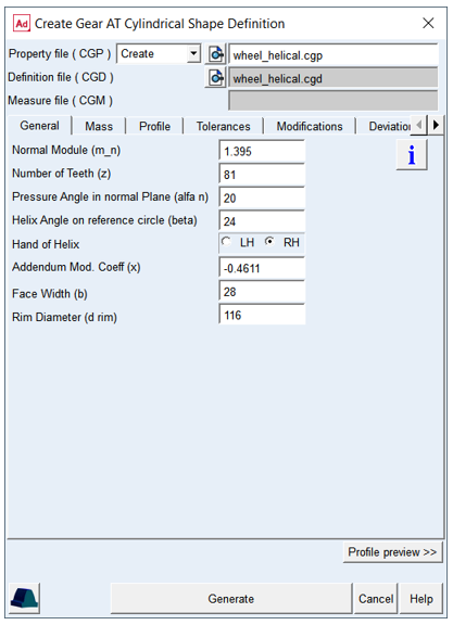
Figure 8 Shape Definition - General tab
For the options | Do the following |
|---|---|
Normal Module (m_n) | Enter value of module in normal plane of a tooth |
Number of Teeth (z) | Enter number of teeth of a gear |
Pressure Angle in normal Plane (alfa n) | Enter value of angle at the pitch diameter between the line of pressure and the line tangent to the pitch circle |
Helix Angle on reference circle (beta) | The helix angle defines the slope of the tooth in lead direction against the rotational axis at the pitch diameter. A positive sign corresponding with the right hand rule. A spur gear has helix angle of zero |
Hand of Helix | Defines whether the helix is left handed (negative) or right handed (positive) |
Addendum Mod. coeff (x) | This factor is positive, when the reference profile is moved away from a gear by the amount of module * factor. Positive factor increases tooth thickness at pitch circle while negative factor decreases |
Face Width (b) | The length of tooth flank in lead direction |
Rim Diameter | The Rim Diameter defines the boundary of the gear rim to the finite element model of the wheel body |
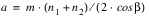
Normal Module
The Normal Module and the Number of teeth are the fundamental variables in defining a gear wheel; the module is often standardized. Following variables and basic equations explain the relation between the module, pitch diameter and the number of teeth in absence of profile modifications.
m ... normal module
n ... number of teeth
p ... pitch
P ... diametral pitch
d ... pitch diameter
 ... helix_angle
 | (1) |
 | (2) |
The theoretical distance between two wheel centers without modification is given by
 | (3) |
Number of Teeth
A positive integer defines number of teeth of an external gear while a negative integer a number of teeth of an internal gear.
Pressure Angle in normal Plane
The normal pressure angle is the angle at the pitch diameter between the line of pressure and the line tangent to the pitch circle; see Figure 9.
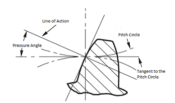
Figure 9 Normal Pressure Angle
Helix angle
The helix angle defines the slope of the tooth in lead direction against the rotational axis at the pitch diameter (Figure 10). A positive sign corresponds with the right hand rule. A straight spur gear has helix angle of zero.
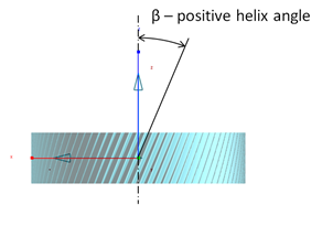
Figure 10 Helix angle
Hand of Helix
Defines whether the helix is left handed (negative) or right handed (positive)
Addendum modification coefficient
This factor is positive, when the reference profile is moved away from a gear by the amount of module * factor. Positive factor increases tooth thickness at pitch circle while negative factor decreases.
Face Width
The length of tooth flank in lead direction
If this value is set to zero, following default (see Equation (4)) will be set
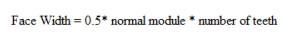 | (4) |
Each gear wheel has a reference marker in the middle of the gear rim of width W; the marker can be placed on any rigid or flexible body. The Z-axis of this reference marker represents the rotation axis of the gear wheel as shown on Figure 11.
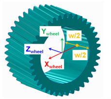
Figure 11 Face Width
Rim diameter
The rim diameter for an external gear and the bore diameter for an internal gear define the boundary of the gear rim (as solid and as finite element model) with the wheel body (Figure 12).
If bore or rim diameter are left to zero, the default is defined by Equation (5). Negative sign holds for external gear and positive sign holds for internal gear. However, the rim thickness should be in the range of  . If user input is out of the range it is automatically adjusted and warning message is issued to the log file.
. If user input is out of the range it is automatically adjusted and warning message is issued to the log file. | (5) |
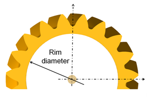
Figure 12 Rim diameter
Hit the button  to open info window with the content of current *.cgp property file.
to open info window with the content of current *.cgp property file.Hit the button  to open the mesh dialog box for the current *.cgp property file
to open the mesh dialog box for the current *.cgp property fileThe Profile preview >> button opens the Profile plot window for the current property file as shown in Figure 13.
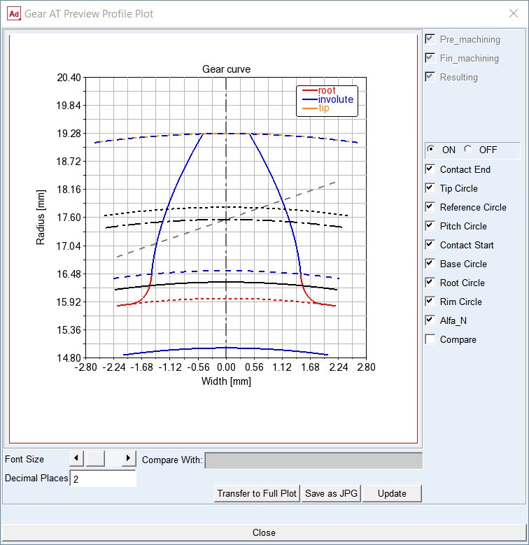
Figure 13 Profile Plot
Mass
The Mass card of the Shape Definition process allows you to define the mass of the gear based either on the Geometry and Material Type or by specific User Input (Figure 14). In the former case the mass, center of mass and inertia tensor is computed later on by the mesher based on FE mesh volume. In the latter case enter all required data in current model units. In either case, inertia data are written to the *.cgp file.
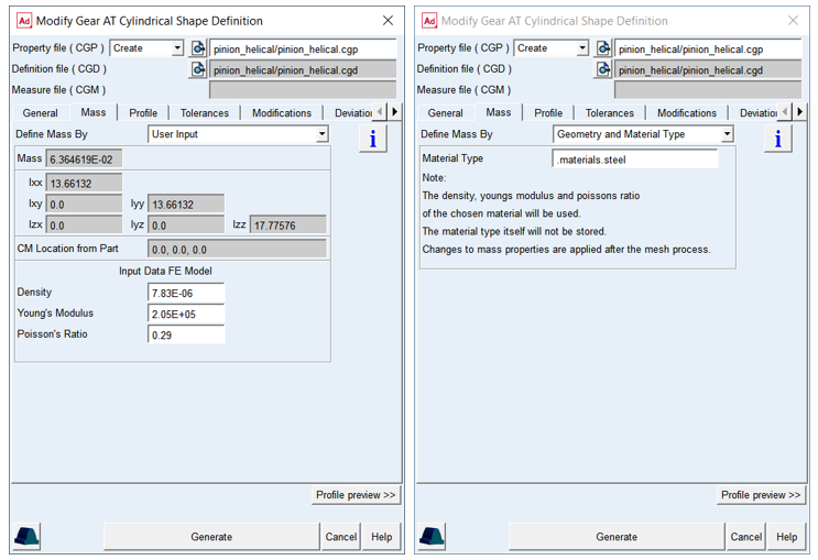
Figure 14 Shape Definition - Mass tab
For the options | Do the following |
|---|---|
Define Mass by | Set to: ■Geometry and Material Type ■User input |
For the option Define Mass by the Geometry and Material Type: | |
Material Type | Choose material type either from predefined material library - right click the field and go to Material - Browse, or create a new one. Note that material of steel is set by default |
For the option Define Mass by the User Input: enter value of Mass, the principal mass moments of inertia (lxx, lyy, lzz) and cross-products of inertia (lxy, lzx, lyz). Note that you still need to define material parameters to define FE model of flexible tooth properly | |
Mass | Enter the mass of the part |
Moments of inertia | Enter the mass moments of inertia |
CM Location from Part | Enter location vector of center of mass expressed in local part reference frame |
Density | Enter Material density to define Nastran MAT1 card of the flexible tooth for SOL101. The value is also used for calculation of the gear wheel inertia properties |
Young‘s Modulus | The Young‘s modulus E is used to define Nastran MAT1 card of the flexible tooth for SOL101. It defines the relation between tensile strain ε and tensile stress σ by Hooke‘s law (Equation (6)), thus defining flexible tooth stiffness. For detailed information: see literature about theory of elasticity |
Poisson‘s Ratio | The Poisson‘s Ratio is used to define Nastran MAT1 card of the flexible tooth for SOL101. An extension εx of a linear elastic and isotropic material is accompanied by lateral strains εy and εz. Poisson‘s ratio defines this relation by Equation (7) and Equation (8) |
Young’s modulus
The Young's modulus E is used to define Nastran MAT1 card of the flexible tooth for SOL101 and SOL103. It defines the relation between tensile strain ε and tensile stress σ by Hooke's law (Equation (6)), thus defining flexible tooth stiffness. For detailed information: see literature about theory of elasticity.
 | (6) |
Poisson’s Ratio
The Poisson’s Ratio is used to define Nastran MAT1 card of the flexible tooth for SOL101 and SOL103. An extension εx of a linear elastic and isotropic material is accompanied by lateral strains εy and εz. Poisson's ratio ν defines this relation by Equation (7) and Equation (8)
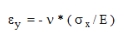 | (7) |
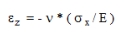 | (8) |
Poisson's ratio can also be derived from the shear modulus G. see Equation (9)
 | (9) |
Profile
The Profile tab defines the proportions of tooth profile which can be specified by different methods of profile definition. The fields and labels change according to selected definition method and input format. For two step generating process additionally the finishing stock is entered here. The one resp. two informative fields show the resulting generating profile shift upon selected method and entered input data.
Tooth profile shape method menu
The tooth profile can be defined by:
■Explicitly defined tooth reference profile
■Cutting tool selection thus simulating cutting process
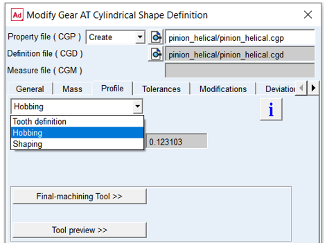
Figure 15 Tooth profile shape method menu
Tooth definition
To define tooth dimensions directly, enter all parameters in the dialog box as shown on Figure 16 for external gear, and Figure 17 for internal gear according to drawing on Figure 18. The Tooth Definition enables user to specify virtual cutting tool for resulting tooth proportions. Internal gears are generated with virtual shaping cutter and external gears with virtual hobbing cutter. Tooth proportions can be defined in form of diameters or coefficients of Normal Module.
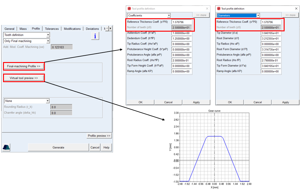
Figure 16 Tooth definition method external gear
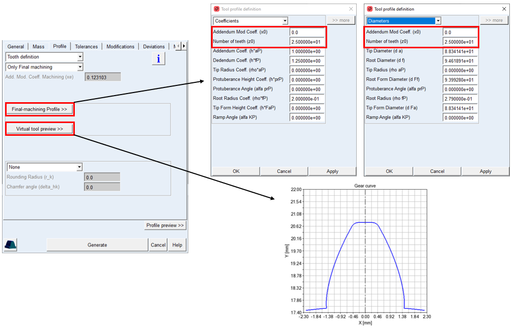
Figure 17 Tooth definition method internal gear
Only Final Machining
This method generates the tooth profile in one step, without additional grinding process, so the thickness and the diameters are defined with one tool. The tooth proportions can be entered in form of diameters or coefficients of Normal Module. The Addendum Mod. Coeff is displayed on the card as informative value, the value differs from Addendum Mod. Coeff in General card as it is corrected due to specified thickness allowance.
For the options | Do the following |
|---|---|
Addendum Mod. Coeff. machining (xe) | The value has informative purpose to see resulting value of generating profile shift: xe = x + Δxjn x = nominal profile shift Δxjn = profilshift due to backlash |
Reference Thickness Coeff. (s*P0) | Applies for external gears. The reference profile is formed by hobbing cutter, so the tool thickness can altered. Default value π/2 corresponds to standard rack profile. |
Addendum Mod. Coeff. (x0) | Applies for internal gears. The reference profile is formed by shaping cutter, so the profile shift can alter the sharper profile due to wear and subsequent tool sharpening |
Number teeth (z0) | Applies for internal gears. Specifies number of teeth for shaping cutter tool. In case the number of teeth is too small to cut the requested gear wheel, the profile generator calculates minimum required number of teeth for cutter |
Addendum Coeff. (h*aP) Tip Diameter (d a) | The value defines addendum height of the gear tooth. This entry can be specified either in form of coefficient h*aP or diameter d a. Typical value is: h*aP = 1.0 d a = pitch diameter + (xe + 1.0)* 2 * normal module |
Dedendum Coeff. (h*fP) Root Diameter (d f) | The value defines the dedendum height of the gear tooth. This entry can be specified either in form of coefficient h*fP or diameter d f. Dedendum values usually includes tip clearance of 0.25 * normal module. Typical value is: h*fP = 1.25 d f = pitch diameter + (xe − 1.25)* 2 * normal module |
Tip Radius Coeff. (rho*aP) Tip Radius (rho aP) | The value defines rounding section on a tip of gear tooth |
Protuberance Height Coeff. (h*prP) Root Form diameter (d Ft) | The value defines the height of undercut section on the root of gear tooth. This entry can be specified either in form of coefficient h*prP or diameter d Ft. When set to zero, the undercut section is not created |
Protuberance Angle (alfa prP) | The value defines the inclination of the undercut section. When set to zero, the undercut section is not created. The value should be lower than normal pressure angle |
Root Radius Coeff. (rho*fP) Root Radius (rho fP) | The value defines the root fillet section on gear tooth. This entry can be specified either in form of coefficient rho*fP or radius rho fP. The radius must be always greater than zero, typical value is: |
Tip Form Height Coeff. (h*FaP) Tip Form Diameter (d Fa) | The value defines the starting point of a tip chamfer. This entry can be specified either in form of coefficient h*Fap or diameter d Fa. When set to zero, the chamfer section is not created |
Ramp Angle (alfa KP) | The value defines the inclination of the chamfer section on gear tooth tip. When set to zero, the chamfer section is not created. The value should be greater than normal pressure angle |
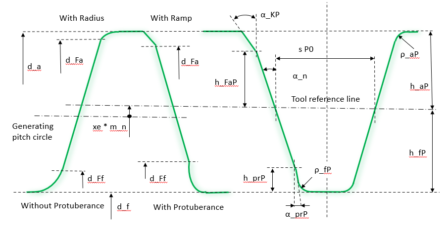
Figure 18 Tooth definition parameters
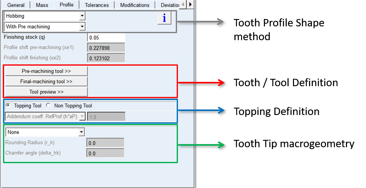
Hobbing
To define a tooth manufactured by hobbing cutter, enter all dimensions of a tool in the dialog box as shown on Figure 19 according to drawing in Figure 21. Please note that unlike the Tooth definition, it expects to define cutter proportions. Here, it is important to realize the fact that addendum portion of a cutter tooth is shaping dedendum portion of a gear tooth. For hobbing one can additionally select in how many steps the profile is generated.
■Only Final Machining - one step cutting, without final grinding, the tooth shape is created only with one tool
■With Pre-machining - two steps cutting, after initial cutting process grinding is applied, in most cases only the involute portions is treated
Only Final Machining
This method generates the tooth profile in one step, without additional grinding process, so the thickness and the diameters are defined with one tool. The tooth proportions can be entered in form of diameters or coefficients of Normal Module. The Addendum Mod. Coeff machining is displayed on the card as informative value, the value differs from Addendum Mod. Coeff in General card as it is corrected due to specified thickness allowance.
For the options | Do the following |
|---|---|
Addendum Mod. Coeff machining (xe) | The value has informative purpose to see resulting value of generating profile shift: xe = x + Δxjn x = nominal profile shift Δxjn = profilshift due to backlash |
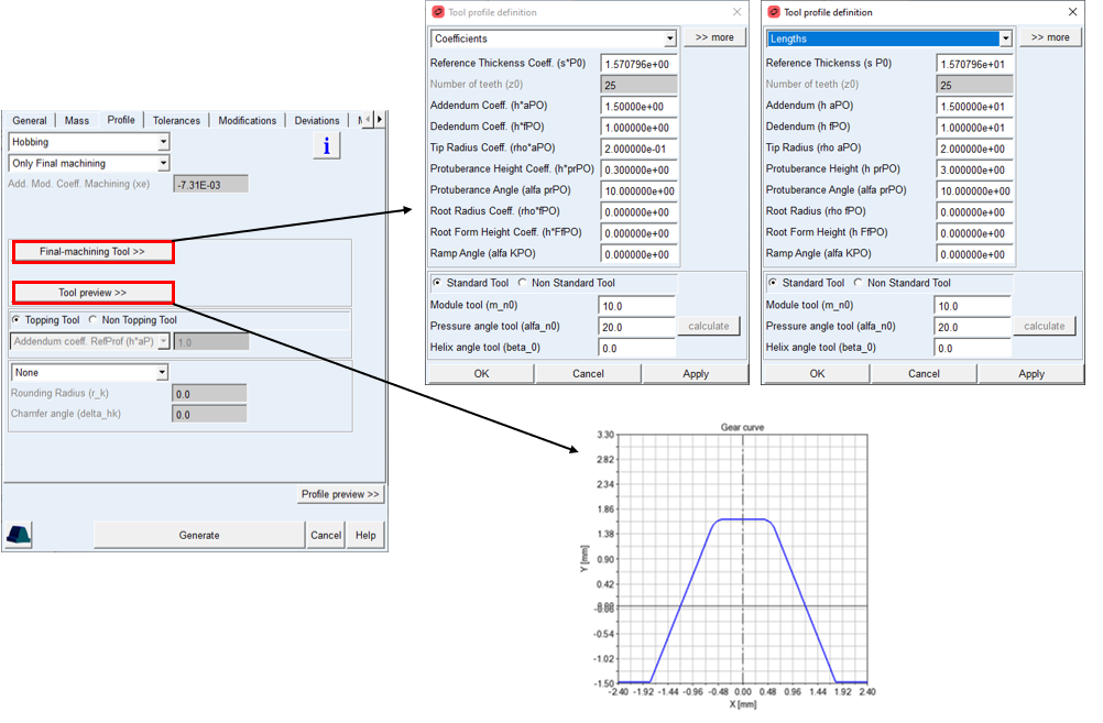
Figure 19 Hobbing cutter method - Only Final Machining
Standard / Nonstandard Tool
The only requirement for involute gears to be conjugate is that the normal base pitch of both gears has to be the same. The normal base pitch is the distance normal to adjacent tooth flanks along a line tangent to the base circle. For hobbing tool one can specify so called Off lead tool (either short or long), in this case the pressure angle of the tool differs from the nominal pressure angle of the generating gear. To meet the requirement of identical normal base pitch the module and helix angle of the tool need to be adjusted to the tool pressure angle. This technique is extensively used for manufacturing pinion gears where the intersection between involute and root must be as low as possible. To match the module and helix angle to the tool pressure angle a calculator is available in the dialog box.
For the options | Do the following |
|---|---|
Module tool (m_n0) | This value represents Normal Module for hobbing tool. The value is different from gear Normal Module in case “Off lead” resp. Nonstandard hobbing tool, in this case it can be calculated with calculator button for selected Pressure angle tool |
Pressure angle tool (alpha_n0) | This value represents Pressure angle for hobbing tool. The value is different from gear Pressure angle in case of “Off lead” resp. Nonstandard hobbing tool |
Helix angle tool beta_0) | This value represents Helix angle for hobbing tool. The value is different from gear Helix angle in case of “Off lead” resp. Nonstandard hobbing tool, in this case can be calculated with calculator button for selected Pressure angle tool. |
The final machining tool is defined with set of parameters described in next table, the meaning is also displayed on left side of Figure 21.
For the options | Do the following |
|---|---|
Reference Thickness Coeff. (s*P0) Reference Thickness (s P0) | The tool thickness can be adjusted with this parameter. Default value π/2 corresponds to standard rack profile. |
Addendum Coeff. (h*aP0) Addendum (h aP0) | The value defines addendum height of the cutter tooth. This entry can be specified either in form of coefficient h*aP0 or length h aP0. The value of addendum specifies the dedendum height of the gear tooth. The values usually includes tip clearance of 0.25 * normal module. Typical value is: h*aP0 = 1.25 h aP0 = 1.25 * normal module |
Dedendum Coeff. (h*fP0) Dedendum (h fP0) | The value defines the dedendum height of the cutter tooth. This entry can be specified either in form of coefficient h*fP0 or length h fP0. The value of dedendum specifies the addendum height of a gear tooth in case topping is activated. Typical value is: h * fP0 = 1.0 h fP0 = 1.0 * normal module |
Tip Radius Coeff. (rho*aP0) Tip Radius (rho aP0) | The value defines arc section between tip and cutting edge of the tip of cutter tooth. This entry can be specified either in form of coefficient rho*aP0 or radius rho aP0. The arc section forms the root fillet on gear tooth profile. |
Protuberance Height Coeff. (h*prP0) Protuberance Height (h prP0) | The value defines height of protuberance section on the tooth of cutter tool. This entry can be specified either in form of coefficient h*prP0 or length h prP0. When set to zero, the protuberance section is not created. The protuberance section generates undercut on the root of a gear tooth. |
Protuberance Angle (alfa prP0) | The value defines the inclination of the protuberance section. When set to zero, the protuberance section is not created. The value should be lower than the normal pressure angle. |
Root Radius Coeff. (rho*fP0) Root Radius (rho fP0) | The value defines the arc section between root and cutting edge of the cutter tooth profile. This entry can be specified either in form of coefficient rho*fP0 or radius rho fP0. The arc section, when large enough, forms the tip rounding on the tip of a gear tooth. |
Root Form Height Coeff. (h*FfP0) Root Form Height (h FfP0) | The value defines the starting point of the ramp portion on the cutter tooth. This entry can be specified either in form of coefficient h*FfP0 or length h FfP0. When set to zero, the ramp section is not created. The ramp section creates chamfer on the tip of a gear tooth. |
Ramp Angle (alfa KP0) | The value defines the inclination of the root ramp section of cutter tooth. When set to zero, the ramp section is not created. The value should be greater than the normal pressure angle. |
With Pre-machining
This method generates the tooth profile in two steps, after initial Pre-machining, grinding process (Final machining) treats in most cases only the involute portion of the tooth, so the thickness and the diameters are defined independently. The tool proportions can be entered in form of length or coefficients of Normal Module. The Machining Allowance defines the amount of material added on the involute profile for grinding process.
The Addendum Mod. Coeff Pre-Mach and Addendum Mod. Coeff Finishing are displayed on the cards as informative values, the values differ from Profile shift coefficient in General card as those are corrected due to specified Thickness Allowance and Machining allowance.
For the options | Do the following |
|---|---|
Machining Allowance (q) | This value represents the additional material to be left on each flank of tooth for final machining. The value is defined along line of action. Currently available for hobbing only |
Addendum Mod. Coeff Pre-Mach (xe1) | The value has informative purpose to see resulting value of generating profile shift: xe1 = x + Δxjn + Δq x = nominal profile shift Δxjn = profil shift due to backlash Δq = profil shift due to finishing stock |
Addendum Mod. Coeff Finishing (xe2) | The value has informative purpose to see resulting value of generating profile shift: xe = x + Δxjn x = nominal profile shift Δxjn = profil shift due to backlash |
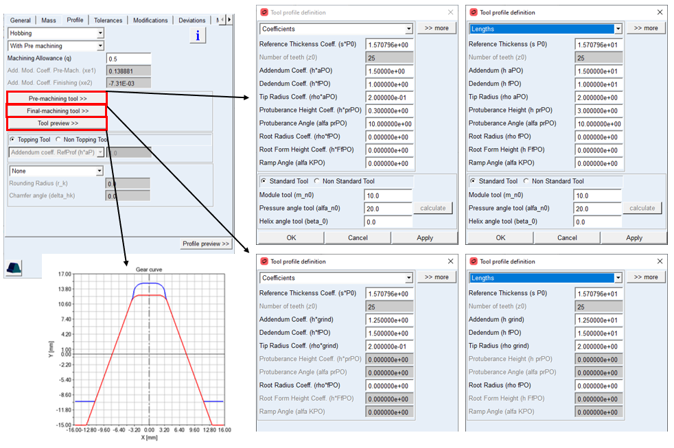
Figure 20 Hobbing cutter method - With Pre machining
Standard / Nonstandard Tool
For the pre-machining hobbing tool with two step manufacturing, one can specify so called “Off lead” tool (either short or long), in this case the pressure angle of the tool differs from the nominal pressure angle of the generating gear. The only requirement for involute gears to be conjugate is that the normal base pitch of both be the same. The normal base pitch is the distance normal to adjacent tooth flanks along a line tangent to the base circle. To meet the requirement of identical normal base pitch the module and helix angle of the tool need to be adjusted to the tool pressure angle. This technique is extensively used for manufacturing pinion gears where the intersection between involute and root must be as low as possible. To match the module and helix angle to the tool pressure angle a calculator is available in the Dialog box.
For the options | Do the following |
|---|---|
Module tool (m_n0) | This value represents Normal Module for hobbing tool. The value is different from gear Normal Module in case of “Off lead” resp. Nonstandard hobbing tool, in this case it can be calculated with calculator button for selected Pressure angle tool |
Pressure angle tool (alpha_n0) | This value represents pressure angle for hobbing tool. The value is different from gear Pressure angle in case of “Off lead” resp. nonstandard hobbing tool |
Helix angle tool (beta_0) | This value represents helix angle for hobbing tool. The value is different from gear Helix angle in case of “Off lead” resp. nonstandard hobbing tool, in this case it can be calculated with calculator button for selected Pressure angle tool |
The Pre-machining tool is defined with set of parameters described in next table, the machining is also displayed on Figure 21 left.
For the options | Do the following |
|---|---|
Reference Thickness Coeff. (s*P0) Reference Thickness (s P0) | The tool thickness can be adjusted with this parameter. Default value π/2 corresponds to standard rack profile. |
Addendum Coeff. (h*aP0) Addendum (h aP0) | The value defines addendum height of the cutter tooth. This entry can be specified either in form of coefficient h*aP0 or length h aP0. Addendum value usually includes tip clearance of 0.25 * normal module. The value of addendum specifies the dedendum height of the gear tooth. Typical value is: h*aP0 = 1.25 h aP0 = 1.25 * normal module |
Dedendum Coeff. (h*fP0) Dedendum (h fP0) | The value defines the dedendum height of the cutter tooth. This entry can be specified either in form of coefficient h*fP0 or length h fP0. The value of dedendum specifies the addendum height of a gear tooth in case the topping is activated. Typical value is: h*fP0 = 1.0 h fP0 = 1.0 * normal module |
Tip Radius Coeff. (rho*aP0) Tip Radius (rho aP0) | The value defines arc section between tip and cutting edge of the tip of cutter tooth. This entry can be specified either in form of coefficient rho*aP0 or radius rho aP0. The arc section forms the root fillet on gear tooth profile. |
Protuberance Height Coeff. (h*prP0) Protuberance Height (h prP0) | The value defines height of protuberance section on the tooth of cutter tool. This entry can be specified either in form of coefficient h*prP0 or length h prP0. When set to zero, the protuberance section is not created. The protuberance section generates undercut on the root of a gear tooth. |
Protuberance Angle (alfa prP0) | The value defines the inclination of the undercut section. When set to zero, the undercut section is not created. The value should be lower than the normal pressure angle. |
Root Radius Coeff. (rho*fP0) Root Radius (rho fP0) | The value defines the arc section between root and cutting edge of the cutter tooth profile. This entry can be specified either in form of coefficient rho*fP0 or radius rho fP0. The arc section, when large enough, forms the tip rounding on the tip of a gear tooth. |
Root Form Height Coeff. (h*FfP0) Root Form Height (h FfP0) | The value defines the starting point of the ramp portion on the cutter tooth. This entry can be specified either in form of coefficient h*FfP0 or length h FfP0. When set to zero, the ramp section is not created. The ramp section creates chamfer on the tip of a gear tooth. |
Ramp Angle (alfa KP0) | The value defines the inclination of the root ramp section of cutter tooth. When set to zero, the ramp section is not created. The value should be greater than the normal pressure angle. |
The second resp. finishing often called grinding tool is defined similar with parameters defined in text table, and also displayed on Figure 21 right.
For the options | Do the following |
|---|---|
Reference Thickness Coeff. (s*P0) Reference Thickness (s P0) | The tool thickness can be adjusted with this parameter. Default value π/2 corresponds to standard rack profile. |
Addendum coeff. (h*grind) Addendum (h grind) | The value defines the addendum height of the grinding tooth and is defined in the way the grinding tool generates specific / required Root form Diameter on gear tooth. This entry can be specified either in form of coefficient h*grind or length h grind. |
Dedendum Coeff. (h*fP0) Dedendum (h fP0) | The value defines the dedendum height of the grinding tooth. The value should be slightly greater than the dedendum on pre-machining tool. This entry can be specified either in form of coefficient h*fP0 or length h fP0. |
Tip Radius Coeff. (rho*grind) Tip Radius (rho grind) | The value defines arc section between tip and cutting edge of the tip of grinding tooth. This entry can be specified either in form of coefficient rho*grind or radius rho grind. The arc section forms together with Addendum the gear Root form Diameter resp. modify the gear tooth root fillet if requested. |
Root Radius Coeff. (rho*fP0) Root Radius (rho fP0) | The value defines the arc section between root and cutting edge of the grinding tooth profile. This entry can be specified either in form of coefficient rho*fP0 or radius rho fP0 . |
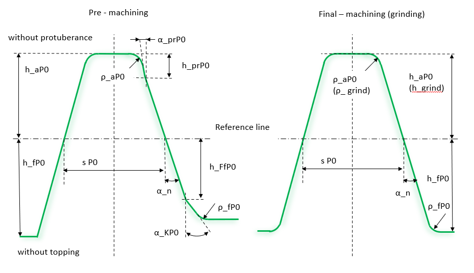
Figure 21 Hobbing cutter parameters
Topping
Activates or deactivates topping, while cutting the gear tooth profile. If activated, the gear tooth addendum height is defined by the cutter tool dedendum height. In case it is deactivated, the gear tooth height is defined by the Addendum Coefficient RefProf (h*aP), Addendum Length RefProf (h aP), resp. Tip Diameter Gear (d a); see Figure 22
Addendum Reference Profile (h*aP) / (h aP), Tip Diameter Gear (d a)
The value defines the addendum height of the gear tooth relative to reference circle, resp. addendum height of the reference profile for the case topping is not activated. This entry can be specified in form of coefficient h*aP, length h aP or tip diameter d a.
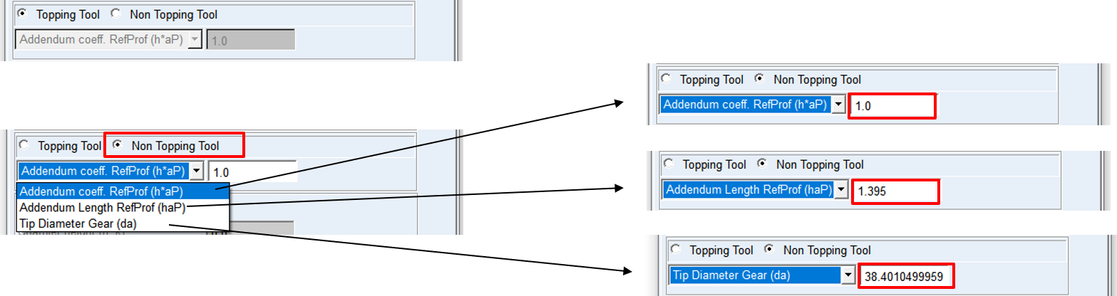
Figure 22 Topping Tool menu
Shaping
To define a tooth manufactured by pinion cutter, enter all parameters as shown in the dialog box on the Figure 23 according to drawing in Figure 24. Please note that unlike the Tooth definition, it expects to define cutter proportions. Here, it is important to realize the fact that addendum portion of a cutter tooth is shaping dedendum portion of a gear tooth.
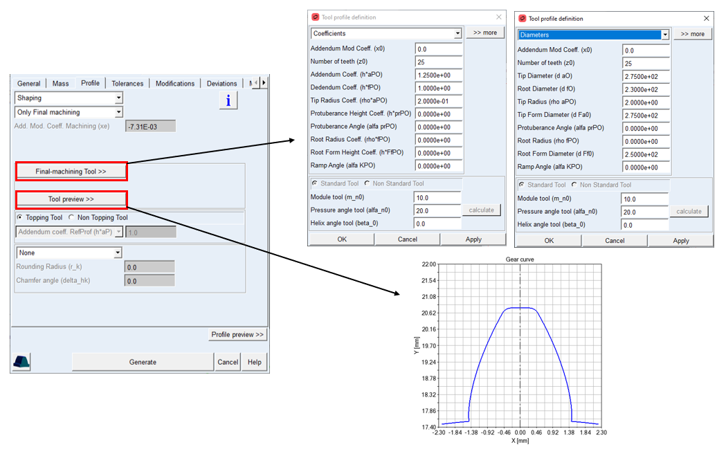
Figure 23 Shaping cutter method
Only Final Machining
This method generates the tooth profile in one step, without additional grinding process, so the thickness and the diameters are defined with one tool. The tool proportions can be entered in form of diameters or coefficients of Normal Module. The Addendum Mod. Coeff. Machining is displayed on the card as informative value, the value differs from Addendum Mod. Coeff. in General card as it is corrected due to specified thickness allowance.
For the options | Do the following |
|---|---|
Addendum Mod. Coeff. Machining (xe) | The value has informative purpose to see resulting value of generating profile shift: xe = x + Δxjn x = nominal profile shift Δxjn = profil shift due to backlash |
The shaping tool cannot be defined as Nonstandard tool in this release.
For the options | Do the following |
|---|---|
Addendum Mod. Coeff. (x0) | The cutter tool profile corresponds to a gear profile, so the addendum modification coeff. can adjust the shaper thickness so it reflects shaper profile after sharpening due to wear. |
Number of Teeth (z0) | Specifies number of teeth for shaping cutter tool. In case the number of teeth is too small to cut the requested gear wheel, the profile generator calculates minimum required number of teeth for cutter. |
Addendum Coeff. (h*aP0) Tip Diameter (d a0) | The value defines addendum height of the cutter tooth. This entry can be specified either in form of coefficient h*aP0 or diameter d a0. Addendum values usually include tip clearance of 0.25 * normal module. Typical value is: h*aP0 = 1.25 d a0 = cutter pitch diameter + (x0 + 1.25) * 2.0 * normal module |
Dedendum Coeff. (h*fP0) Root Diameter (d f0) | The value defines the dedendum height of the cutter tooth. This entry can be specified either in form of coefficient h*fP0 or diameter d f0. The value of dedendum specifies the addendum height of the gear tooth in case topping is activated. Typical value is: h*fP0 = 1.0 df0 = cutter pitch diameter +(x0 − 1.0) * 2.0 * normal module |
Tip Radius Coeff. (rho*aP0) Tip Radius (rho aP0) | The value defines arc section between tip and cutting edge of the tip of cutter tooth. This entry can be specified either in form of coefficient rho*aP0 or radius rho aP0. The arc section forms the root fillet on gear tooth profile. |
Protuberance Height Coeff. (h*prP0) Tip Form Diameter (d Fa0) | The value defines height of protuberance section on the cutter tooth. This entry can be specified either in form of coefficient h*prP0 or diameter d Fa0. The protuberance section creates undercut on the root of gear tooth |
Protuberance Angle (alfa prP0) | The value defines the inclination of the undercut section. When set to zero, the undercut section is not created. The value should be lower than the normal pressure angle. |
Root Radius Coeff. (rho*fP0) Root Radius (rho fP0) | The value defines the arc section between root and cutting edge of the cutter tooth profile. This entry can be specified either in form of coefficient rho*fP0 or radius rho fP0. The arc section, when large enough, forms the tip rounding on the tip of a gear tooth. |
Root Form Height Coeff. (h*FfP0) Root Form Diameter (d Ff0) | The value defines the starting point of the ramp portion on the cutter tooth. This entry can be specified either in form of coefficient h*FfP0 or diameter d Ff0. The ramp section generates chamfer on the tip of a gear tooth. When set to zero, the ramp section is not created |
Ramp Angle (alfa KP0) | The value defines the inclination of the root ramp section of cutter tooth. When set to zero, the ramp section is not created. The value should be greater than the normal pressure angle. |
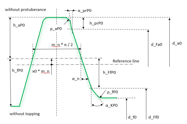
Figure 24 Shaping cutter parameters
Topping
Activates or deactivates topping, while cutting the gear tooth profile. If activated, the gear tooth addendum height is defined by the cutter tool dedendum height. In case it’s deactivated, the gear tooth height is defined by the Addendum Coefficient RefProf (h*aP), Addendum Length RefProf (haP), resp. Tip Diameter Gear (da).
Addendum Reference Profile (h*aP), / (haP) / Tip Diameter Gear (da)
The value defines the addendum height of the gear tooth relatives to reference circle, resp. addendum height of the reference profile for the case topping is not activated. This entry can be specified in form of coefficient h*aP, length haP or tip diameter d a.
Figure 25 Topping Tool menu
Tooth macro geometry
The macro geometry modifies the generated tooth profile after machining with tool or definition with reference profile. The macro geometry can not be applied if tool or reference profile already apply explicitly these modifications during the generating process. In current release only following modifications are supported:
■Rounding in transversal plane: radius between tip circle and involute in transversal plane, the radius is smoothly attached on both ends to the remaining profile, see Figure 26.
■Chamfer: the edge brake is formed by line, applied at height hk from tip diameter and angle δhk from vertical, see Figure 26.
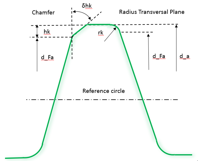
Figure 26 Macro geometry definition
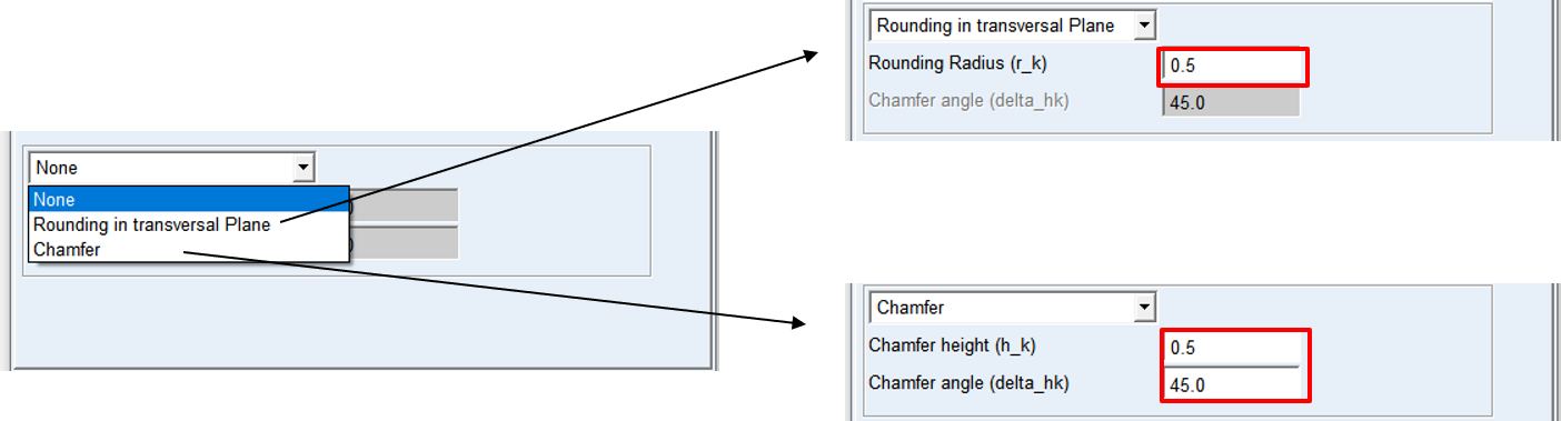
Figure 27 Tooth Tip shape definition
Tolerances
The Tolerances card includes definition of tooth thickness, tip and root diameter allowances. The tooth thickness allowance can be defined either directly or via normal or circular backlash, the allowance can be also defined from Dimension Over Balls and Base Tangent Length measurement.
In case neither of the measurement is known, one can initialize the measurements with Init Measurement buttons, this sets either optimal value of the Measurement ball diameter or the value of Number teeth spanned and it derives the measurement for given thickness allowance input.
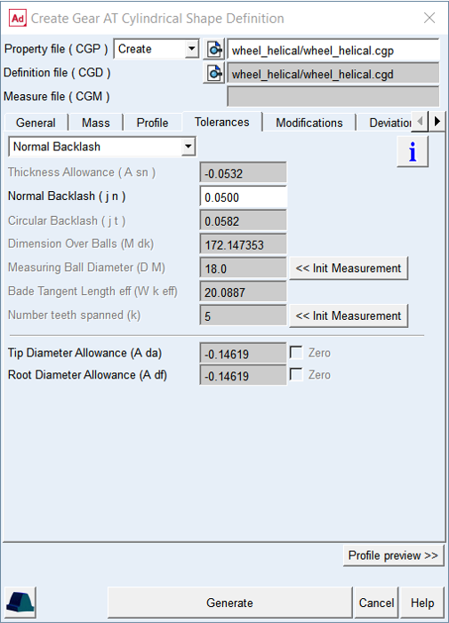
Figure 28 Shape Definition - Tolerance Tab
For the options | Do the following |
|---|---|
Normal Thickness Allowance (A sn) | The value represents alternation of tooth thickness at the reference circle in the normal plane |
Normal Backlash (j n) | The entered value represents the portion of the total backlash in normal plane along line of action, applied on the respective gear wheel. |
Circumferential Backlash (j t) | The entered value represents the portion of the total backlash in form of arc length on reference circle in transversal plane, applied on the respective gear wheel. |
Dimension Over Balls (M dk) | The Dimension over balls can be used to define the thickness allowance from measurement together with Measuring ball diameter |
Measuring Ball Diameter (D M) | The diameter of measuring ball can be used to indirectly define the tooth thickness allowance together with Dimension Over Balls M dK. Diameter of measuring ball is also used for gear generator to calculate dimensions over balls for the generated profile |
Base Tangent Length ( W k eff) | The Effective Base tangent length can be used to indirectly define the tooth thickness allowance together with Number of teeth spanned. |
Number Teeth Spanned (k) | Number of teeth spanned can be used to indirectly define the tooth thickness allowance together with Effective Base tangent length. The number of teeth the instrument is placed over, depends on the total number of teeth, the pressure angle and helix angle of a gear. |
Tip Diameter Allowance (A da) | The value represents the alternation of Tip Diameter on respective gear wheel. |
Root Diameter Allowance (A df) | The value represents the alternation of Root Diameter on respective gear wheel. |
Zero toggles | If the tip resp. root diameter allowance is not of interest, one can check this toggle, then the selected diameter allowance is hold zero and not influenced by thickness allowance settings. |
Extended definition:
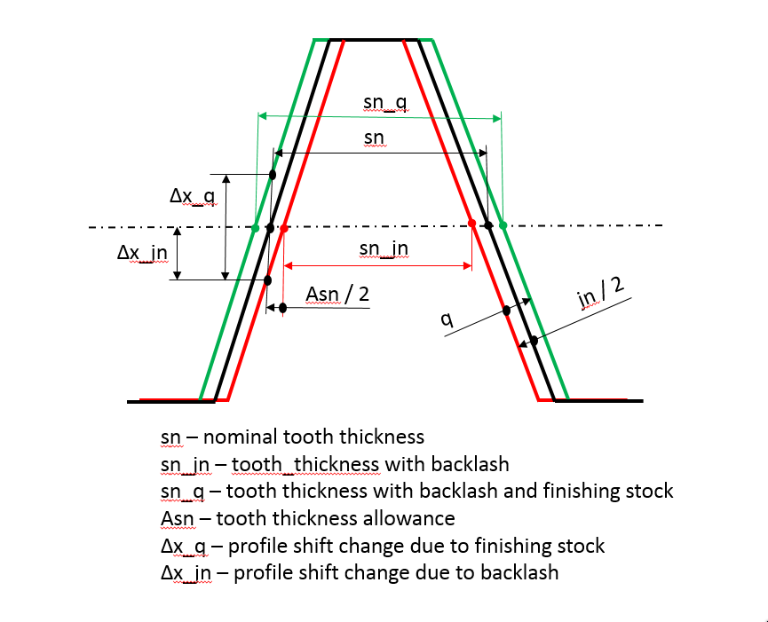
Figure 29 Thickness relation to backlash and finishing stock
Normal Thickness Allowance (A sn)
The value defines the alternation of tooth thickness. Usually, the nominal tooth thickness is adjusted to ensure smooth operation of the gear pair allowing for pitch and radial deviations, gear misalignments due to assembly or system deflections to not cause unintended contact between the gear teeth, like tooth interference and/or backside contact. The relation to backlash is depicted on Figure 29.
Normal Backlash (j_n)
The value represents just another way to define Thickness Allowance. The entered value represents the portion of the total backlash applied on the respective gear wheel in normal plane along line of action. It is the shortest distance between the non-working flanks of a gear pair when their working flanks are in contact.
Circumferential Backlash (j t)
The value represents just another way to define Thickness Allowance. The entered value represents the portion of the total backlash applied on the respective gear wheel as an arc length in radians on the reference circle in the transversal plane.
Dimensions Over Balls (M dk) / Measuring Ball Diameter (D M)
Measurement over the balls or pins enables indirect determination of the tooth Thickness Allowance. A measuring ball or pin is placed in two tooth spacing which are opposite to each other (see Figure 31). The Dimension Over Balls and Measuring Ball Diameter are the values to be entered accordingly to measurement process. The Measuring Ball Diameter is also input for gear generator which calculates Dimension Over Balls for comparison with real measurement (Figure 32).
Base tangent length (W k eff) / Number of teeth spanned (k)
Effective Base tangent length enables indirect determination of the tooth thickness allowance.
The tooth thickness is evaluated from the effective base tangent length W k eff (Figure 30), which is measured over a specific number of teeth. The number of teeth the instrument is placed over, depends on the total number of teeth, the pressure angle, the helix angle and width of a gear.
The number teeth spanned is also used for the computation of the effective base tangent length W k eff and the base tangent length W k (without backlash) by the profile generator and outputs resulting value for comparison with real measurement (Figure 32).
Number Teeth Spanned (k)
It is used for the computation of the effective base tangent length Wk and the base tangent length (without backlash) by the profile generator and outputs resulting value for comparison with real measurement (Figure 32). The tooth thickness is evaluated from the effective base tangent length Wk (Figure 30), which is measured over a specific number of teeth. The number of teeth the instrument is placed over, depends on the total number of teeth, the pressure angle and helix angle of a gear.
Tip Diameter Allowance (A da)
The value represents the alternation of Tip Diameter on respective gear wheel. The allowance is not available if tool with topping ( shaping or hobbing) generates the profile, in this case the tool adjustment due to thickness allowance defines the allowance.
Root Diameter Allowance (A df)
The value represents the alternation of Tip Diameter on respective gear wheel. The allowance is not available if tool ( shaping or hobbing) generates the profile, in this case the tool adjustment due to thickness allowance defines the allowance.
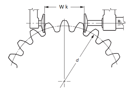
Figure 30 Teeth Span Measurement
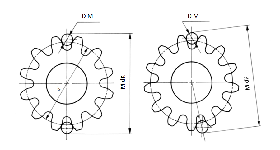
Figure 31 Measurement over pins/balls
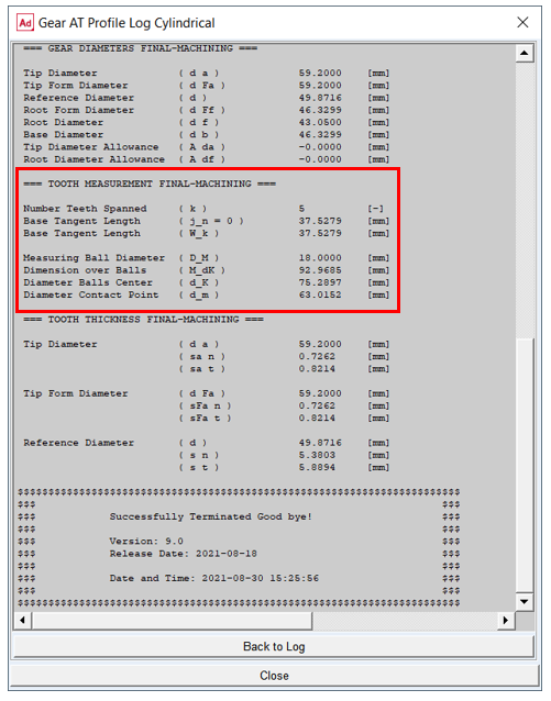
Figure 32 Tooth measurements output from profile generator
Modifications
Gear tooth flank modifications are applied to compensate for manufacturing errors, deformation of the teeth due to load and also for shafts and housing deformation thus ensure a proper meshing to achieve more favorable load distribution and reduced transmission error. The ultimate goal is to reduce gear wear and vibrations induced by the gear pair operation, thus help to design durable gearbox fulfilling specified NVH parameters.
The convention for tooth flank side used throughout the Gear AT is based on ISO standards (Figure 31). The modification amount is defined in transversal plane and perpendicular to profile curve. The principal definition is based on ISO DIN 21771 and ISO DIN 1328-1 2018.
Important: | Values of gear modifications are usually defined in units of micrometers in gear specification sheets or drawings. However, values of all parameters have be entered in model units! |
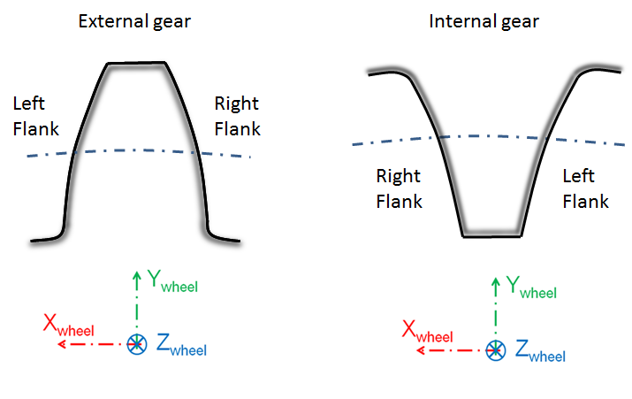
Figure 33 Definition of left and right flank
The topology modifications are divided in Gear AT into 3 main groups:
User can enter values individually for each group on left or right flank, after opening dedicated dialog box with group button under Topology setting section. The input can be entered indentical for both flanks after checking Symmetric Left Right Flank toggle before opening the group dialog box. See Figure 34.
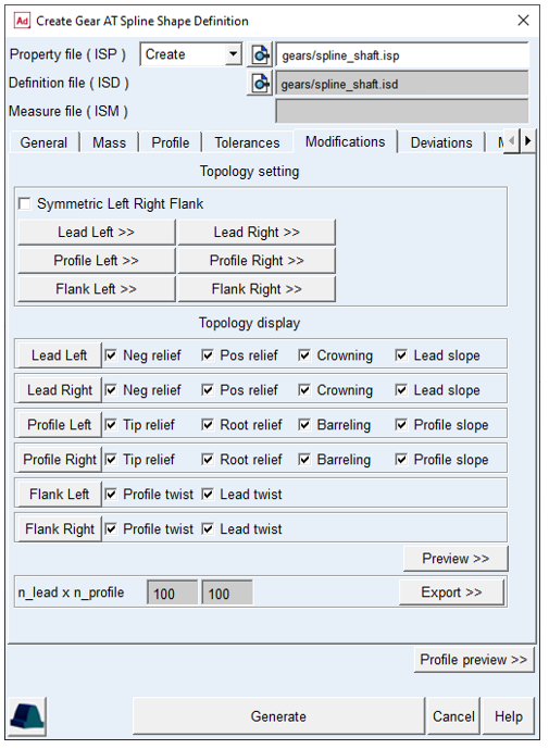
Figure 34 Shape Definition - Modifications tab
Lead Modification
Lead modifications are used to attain a low displacement sensitivity and to avoid strain peaks occurring due to displaced positions of the gear axis or helix deviations of the flank. Types of lead modifications for gear supported by Gear AT include longitudinal end relief, crowning and lead slope changes. The Figure 35 shows the lead modifications tab layout for the left flank.
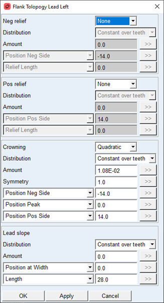
Figure 35 Lead Modification dialog box
End Relief (Pos relief, Neg relief)
End relief is used to avoid stress concentrations at the edges due to angular misalignment of a gear pair. This type of tooth modification is preferably used on wider gears.
For the options | Do the following |
|---|---|
End Relief Neg / Pos | The relief can have Linear, Quadratic or Cubic shape. The Quadratic shape is in most cases equivalent with circular and parabolic shape. Selecting None deactivates the relief. Default option = None |
Distribution | The option Constant over teeth sets the nominal value of given parameter for each tooth the same, while the option Individual per tooth combines nominal value with deviations defined for each tooth. |
Amount (C_b_I / C_b_II) | This parameter defines how much material is added or removed by the relied. Positive value means material is removed. Default value = 0.0 |
End Relief Neg / Pos Position | The amount of relief is applied at the position defined by this parameter. It has the meaning of gear width starting in the middle of gear width, spanning from middle to pos. resp. neg. gear side. In addition to the user input, the Position Neg Side / Position Pos Side option, there is predefined value of position at the negative and positive half width, the Position Neg Gear Side / Position Pos Gear Side Neg relief: Default value = Position Neg Gear Side Pos relief: Default value = Position Pos Gear Side |
End Relief Neg / Pos Length (L_CI_2 / L_CII_2) | This parameter defines the start position of the end relief along lead direction which is measured from the end relief position. Default value = 0.0 |
The End Relief modifications with the principal parameters are depicted on figure Figure 36.
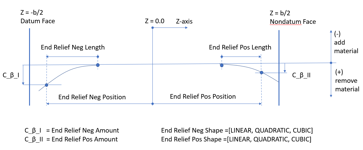
Figure 36 Positive and Negative end relief
Crowning
Crowning is convex shape along the width of a tooth. It is used to maintain contact in the central region of the tooth flank width allowing for spline angular and axial misalignment. This type of tooth modification is preferably used on narrow gears. The amount of crowning should not be larger than necessary as otherwise it would reduce area of contact, thus lowering load capacity of a spline pair.
For the options | Do the following |
|---|---|
Crowning | The crowning can have Linear, Quadratic or Cubic shape. The Quadratic shape is in most cases equivalent to circular and parabolic shape. Selecting None option deactivates the crowning. Default option = None |
Distribution | The option Constant over teeth sets the nominal value of given parameter for each tooth the same, while the option Individual per tooth combines nominal value with deviations defined for each tooth. |
Amount (C_b_I / C_b_II) | It defines how much material is added/removed by the crowning at the Negative and Positive Position, respectively. Positive value means material is removed. Default value = 0.0 |
Symmetry | This parameter defines the distribution of crowning amount between positive and negative tooth side. The amount applied on positive side is multiplied by this value. Using value of 1.0 defines symmetrical crowning. Default value = 0.0 |
Crowning Position Neg: Position Neg Side Position Neg Gear Side | The amount of crowning is applied at position on the negative side of a tooth defined by this parameter. It has the meaning of gear width starting in the middle of a gear, spanning to negative gear side. In addition to the user input, the Position Neg Side option, there is predefined value of position at the negative half width, the Position Neg Gear Side. Default value = Position Neg Gear Side |
Crowning Position Peak: Position Peak Position Middle | This parameter defines position of the crowning peak, i.e. the point where no material is removed of the flank surface. It has meaning of gear width starting in the middle of a tooth width, spanning from Crowning Position Neg to Crowning Position Pos. In addition to the user input, the Position Peak, there is predefined position in the middle of a tooth width, the Position Middle. Default value = Position Middle |
Crowning Position Pos: Position Pos Side Position Pos Gear Side | The amount of crowning is applied at reference position on the negative side of a tooth defined by this parameter. It has the meaning of gear width starting in the middle of a gear, spanning to positive gear side. In addition to the user input, the Position Pos Side option, there is predefined value of position at the positive half width, the Position Pos Gear Side. Default value = Position Pos Gear Side |
The Crowning modification with the principal parameters is depicted on figure Figure 37.
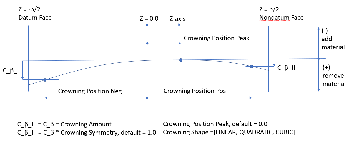
Figure 37 Crowning definition
Lead Slope
Lead Slope defines correction of the helix angle (Figure 38), which is used to improve contact with mating gear teeth when system deflections would otherwise cause edge loading.
For the options | Do the following |
|---|---|
Distribution | The option Constant over teeth sets the nominal value of given parameter for each tooth the same, while the option Individual per tooth combines nominal value with deviations defined for each tooth. |
Amount (C_Hb) | Along with Slope Length it defines the slope by which the flank deviated from the original helix. Positive value increases the absolute value of the helix angle, while negative decreases the absolute value. For straight teeth, a positive value creates right-hand helix, while negative value creates left-hand helix. Default value = 0.0 |
Slope Reference Position: Position at Width Position Neg Gear Side Position Pos Gear Side Auto Width | The parameter defines the position of zero flank change. It has the meaning of gear width starting in the middle of a gear width, spanning from negative to positive gear side. In addition to the user input, the Position at Width option, there are predefined values of position at the gear negative or positive side, the Position Neg Gear Side and Position Pos Gear Side. The Auto Width option adjusts the value in the way the sum of all lead modifications is tangent to the original flank surface at certain point. Default value = 0.0 |
Slope Length (L_b): Length Full Length | The parameter defines the tooth width where the lead slope is applied. Beside the user input, the Length option, a full tooth width is a predefined length value. Default value = Full Length |
The Lead slope modification with the principal parameters is depicted on figure Figure 38.
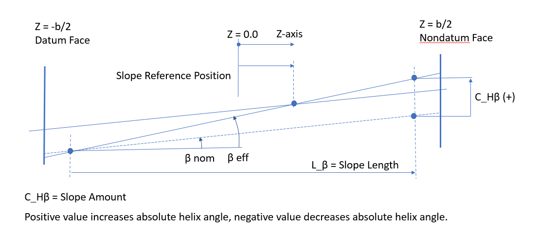
Figure 38 Lead Slope definition
Profile Modifications
Profile modifications are mostly used to decrease the engagement shock and the involved strain and noise. Types of profile modifications supported by Gear AT include tip and root relief, barreling (vertical crowning), and profile slope correction. The figure Figure 39 shows the lead modifications dialog box layout for the left flank.
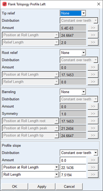
Figure 39 Profile modifications dialog box
The positions of modifications amount along tooth profile are typically expressed against roll length. User has in addition the option to enter instead of roll length also Diameter resp Roll angle value. The different input options are linked together and express the same point on involute point, see Figure 40.
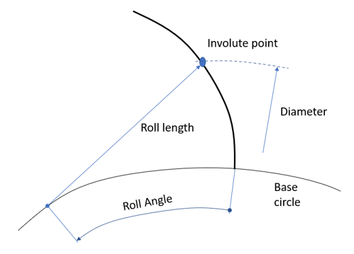
Figure 40 Roll Length, Diameter and Roll Angle relation
Tip and Root Relief
The use of tip relief will cause less noise during gear meshing. Tip relief is the most economical and most common method.
For the options | Do the following |
|---|---|
Tip Relief / Root Relief | The tip and root relief can have Linear, Quadratic or Cubic shape. The Quadratic shape is in most cases equivalent to circular and parabolic shape. Selecting None option deactivates the relief. Defaul option = None |
Distribution | The option Constant over teeth sets the nominal value of given parameter for each tooth the same, while the option Individual per tooth combines nominal value with deviations defined for each tooth. |
Amount (C_aa / C_af) | This parameter defines how much material is added or removed by the relief. Positive value means material is removed. Default value = 0.0 |
Tip / Root Relief Position: Position at Roll Length (L_Caa / L_Caf) Position at Diameter (d_Caa / d_Caf) Position at Roll Angle @Tip Form / Root Form | The amount of relief is applied at the position defined by this parameter. It has the meaning of tooth roll length starting on the base circle and spanning between tip and root form circle. Besides the roll length the value can be entered as diameter or roll angle. In addition to the user input, the Position at Roll Length option, there is predefined value of position on the tip / root form circle, the Position Tip Form Roll Length / Position Root Form Roll Length. Usually, the value should reflect the active tip and root circle, respectively. Tip relief: Default value = Position Tip Form Roll Length Root relief: Default value = Position Root Form Roll Length |
Tip / Root Relief Length: Relief Length (L_Ca / L_Cf) Start at Diameter (d_Ca / d_Cf) Start at Roll Angle | This parameter defines the start position of the relief which is measured from the relief reference position. Default value = 0.0 |
The Tip and Root Relief modifications with the principal parameters are depicted on figure Figure 41.
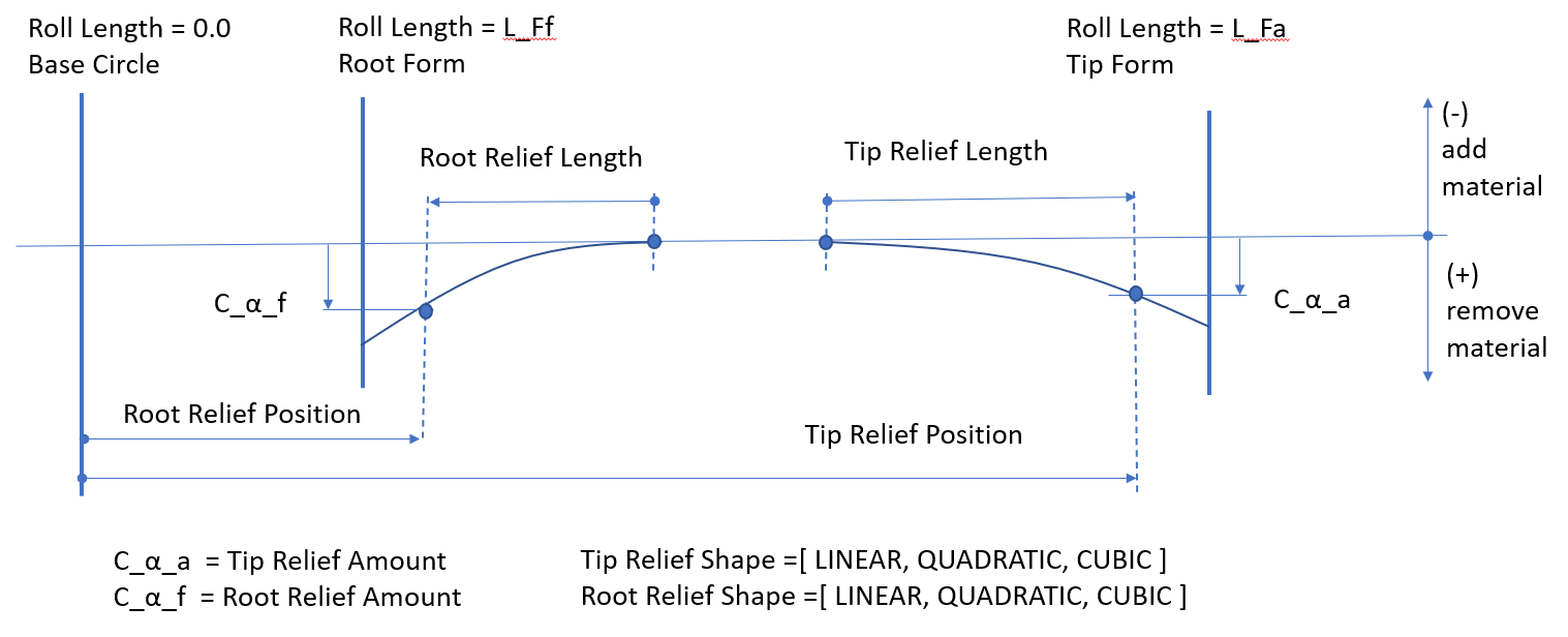
Figure 41 Tip and Root relief definition
Barreling
Profile barreling is a convex shape added to the involute curve to prevent hard contact near the tip and root.
For the options | Do the following |
|---|---|
Barreling | The barreling can have Linear, Quadratic or Cubic shape. The Quadratic shape is in most cases equivalent to circular and parabolic shape. Selecting None option deactivates the barreling Defaul option = None |
Distribution | The option Constant over teeth sets the nominal value of given parameter for each tooth the same, while the option Individual per tooth combines nominal value with deviations defined for each tooth. |
Amount (C_al) | It defines how much material is added/removed by the barreling at the Reference Tip and Root Position respectively. Positive value means that material is removed. Default value = 0.0 |
Symmetry (C_a2 / C_a1) | This parameter defines the distribution of barreling amount between tip and root. The amount applied at root is multiplied by this value. The value of 1.0 defines symmetrical barreling. Defaul valule = 1.0 |
Reference Root Position: Position at Roll Length root (L_Ca2) Position at Diameter root (d_Ca2) Position at Roll Angle root @Root Form | The amount of barreling is applied at the root position defined by this parameter. It has the meaning of tooth roll length starting on the base circle, spanning between tip and root form circle. Besides the roll length the value can be entered as diameter or roll angle. In addition to the user input, the Position at Roll Length root option, there is predefined value of position on the root form circle, the Position Root Form Roll Length. Usually, the value should reflect the active root circle. Default value = Position Root Form Roll Length |
Reference Peak Position: Position at Roll Length peak Position at Diameter peak Position at Roll Angle peak @Middle | This parameter defines position of the barreling peak, i.e the point where no material is removed of the flank surface. It has the meaning of tooth roll length starting on the base circle and having spanning between tip and root form circle. Besides the roll length the value can be entered as diameter or roll angle. In addition to the user input, the Position at Roll Length peak option, there is predefined position in the middle of the roll length, the Position Middle Roll Length i.e., between tip and root. Default value = Position Middle Roll Length |
Reference Tip Position: Position at Roll Length tip (L_Ca1) Position at Diameter tip (d_Ca1) Position at Roll Angle tip @Tip Form | The amount of barreling is applied at the reference tip position defined by this parameter. It has the meaning of tooth roll length starting on the base circle, spanning between tip and root form circle. Besides the roll length the value can be entered as diameter or roll angle. In addition to the user input, the Position at Roll Length tip option, there is predefined value of position on the tip form circle, the Position Tip Form Roll Length. Usually, the value should reflect the active tip circle. Default value = Position Tip Form Roll Length |
The Barreling modification with the principal parameters is depicted on figure Figure 42.
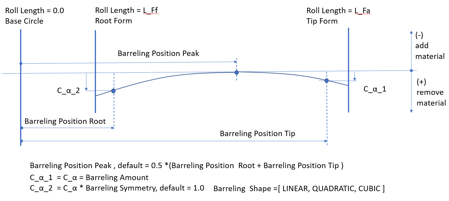
Figure 42 Barreling definition
Profile Slope
Profile slope is used to compensate for tooth deflection differences between the two meshing gears and to compensate for system deflections that would otherwise result in hard contact near the root or the tip of the tooth. It effectively defines correction of pressure angle.
For the options | Do the following |
|---|---|
Distribution | The option Constant over teeth sets the nominal value of given parameter for each tooth the same, while the option Individual per tooth combines nominal value with deviations defined for each tooth. |
Amount (C_Ha) | Along with Slope Length it defines the slope by which the flank deviates from the original involute curve. Positive value has the meaning of added material at the tooth tip for both internal and external gears, resp. decreasing the pressure angle. Default value = 0.0 |
Slope Reference Position: Position at Roll Length (L_CHa) Position at Diameter (d_CHa) Position at Roll Angle @Root Form / Tip Form / Auto | The parameter adjusts the position of zero flank change. It has the meaning of tooth roll length starting on the base circle and having limits between tip and root form circle. In addition to the user input there are predefined values of position on the tip and root form circle. The Auto Position option adjusts the value in the way the sum of all profile modifications is tangent to the original flank surface at a certain point. Default value = Position Root Form Roll Length |
Slope Length: Roll Length (L_a) Full Roll Length | The parameter defines the tooth roll length where the slope is evaluated. Beside the user input, the Roll Length option, a full roll length is a predefined length value. Default value = Full Roll Length |
The Profile slope modification with the principal parameters is depicted on Figure 43.
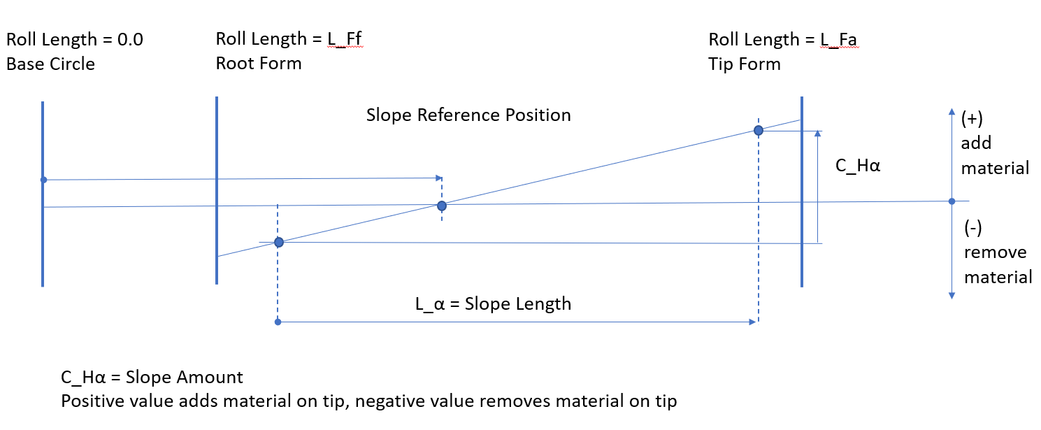
Figure 43 Profile Slope definition
Flank Modifications
Flank modifications effects the flank topology in both the lead and profile direction. In Gear AT we support profile and lead twist modification. The Figure 44 shows the flank modifications dialog box layout for the left flank.
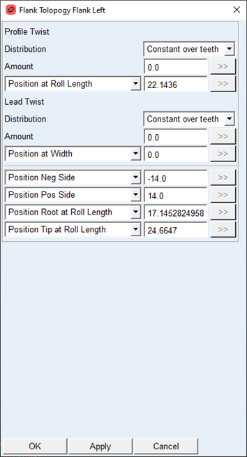
Figure 44 Flank modification dialog box
Profile and Lead Twist
The Profile Twist modification is a flank surface torsion along the tooth width. The twist is applied in correlation with profile slope but always with opposite sign on tooth sides. The Lead Twist modification is a flank surface torsion along the tooth height. The twist is applied in correlation with lead slope but always with opposite sign on tooth tip and root.
For the options | Do the following |
|---|---|
Profile Twist: | |
Distribution | The option Constant over teeth sets the nominal value of given parameter for each tooth the same, while the option Individual per tooth combines nominal value with deviations defined for each tooth. |
Amount (S_a) | The value represents the difference of profile slope between datum and non-datum tooth side. The positive value corresponds to positive profile slope at datum face. The profile slope at non-datum side has opposite sing as the non-datum side Default value = 0.0 |
Profile Reference Position: Position at Roll Length Position at Diameter Position at Roll Angle @ Root Form / Tip Form / Middle | This parameter defines the position of zero flank change. It has the meaning of tooth roll length starting on the base circle, spanning between tip and root form circles. Besides the roll length the value can be entered as diameter or roll angle. In addition to the user input, the Position at Roll Length option, there are predefined values of position on the tip and root form circle and in the middle of the roll length . Default value = Position Root Form Roll Length |
Lead Twist: | |
Distribution | The option Constant over teeth sets the nominal value of given parameter for each tooth the same, while the option Individual per tooth combines nominal value with deviations defined for each tooth. |
Amount (S_b) | The value represents the difference of lead slope between tip and root circle. The positive value corresponds to positive lead slope at tip circle. The profile slope on the root circle has opposite sign as on the tip circle Default value = 0.0 |
Lead reference Position: Position at Width Position Neg Gear Side Position Pos Gear Side Position Middle | The value adjusts the position of zero flank change. It has the meaning of tooth width starting in the middle of a gear width, spanning between positive resp. negative gear sides. In addition to the user input, the Position at Width option, there are predefined values of position at the gear negative or positive side and in the middle of a gear width. Default value = Position Middle |
Lead reference position to apply amount of Profile Twist and Lead Twist | |
Position Neg Side Position Neg Gear Side | The parameter defines the amount of twist applied on the flank surface defined along the tooth width at negative position. It has the meaning of tooth width starting in the middle of a tooth width, spanning to negative gear side. In addition to the user input, the Position Neg Side option, there is predefined value of position at the negative half width, the Position Neg Gear Side. Default value = Position Neg Gear Side |
Position Pos Side Position Pos Gear Side | The parameter defines the amount of twist applied on the flank surface defined along the tooth width at positive position. It has the meaning of tooth width starting in the middle of a gear, spanning to positive gear side. In addition to the user input, the Position Pos Side option, there is predefined value of position at the positive half width, the Position Pos Gear Side Default value = Position Pos Gear Side |
Profile reference position to apply amount of Profile Twist and Lead Twist | |
Position Root at Roll Length Position Root at Diameter Position Root at Roll Angle @ Root Form | The parameter defines the amount of twist applied on the flank surface defined along the roll length at root position. It has the meaning of tooth roll length starting on the base circle, spanning between tip and root form circle. Besides the roll length the value can be entered as diameter or roll angle. In addition to the user input, the Position Root at Roll Length option, there is predefined value of position on the root form circle, the Position Root Form Roll Length. Usually, the value should reflect the active root circle. Default value = Position Root Form Roll Length |
Position Tip at Roll Length Position Tip at Diameter Position Tip at Roll Angle @ Tip Form | The parameter defines the amount of twist applied on the flank surface defined along the roll length at tip position. It has the meaning of tooth roll length starting on the base circle, spanning between tip and root form circle. Besides the roll length the value can be entered as diameter or roll angle. In addition to the user input, the Position Tip at Roll Length option, there is predefined value of position on the tip form circle, the Position Tip Form Roll Length. Usually, the value should reflect the active tip circle. Default value = Position Tip Form Roll Length |
The Profile twist modification and Lead twist modifications with the principal parameters is depicted on Figure 45 and on Figure 46., respectively.
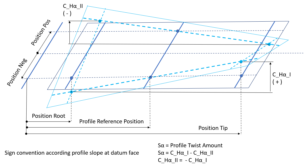
Figure 45 Profile Twist definition
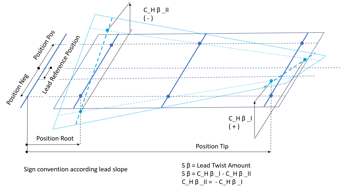
Figure 46 Lead Twist definition
Topology Preview
You can preview applied modifications either individually or superimposed over the tooth flank as shown in Figure 47. The individual modifications can be switched On or Off in the Topology display container in the Microgeometry tab so only selected are displayed in the preview dialog box.
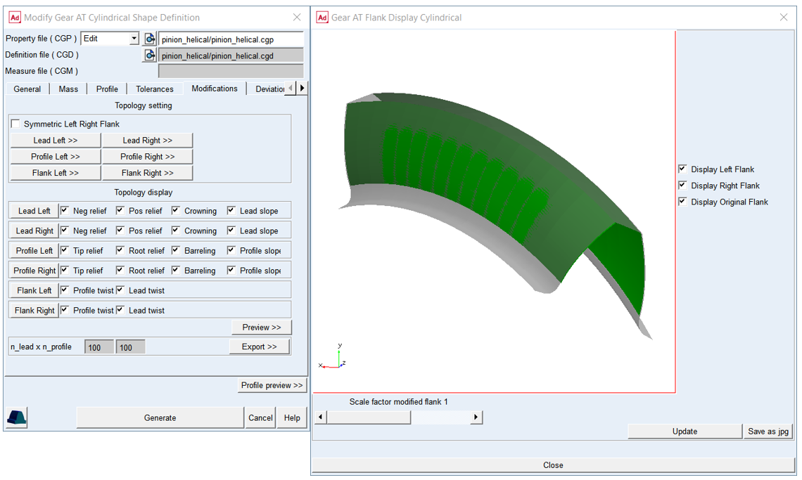
Figure 47 Topology preview
Topology Deviations
The distribution of the microgeometry over teeth can be defined in dedicated dialog box, user can select between harmonic or random number generated distribution or can insert self-generated distribution of value or deviation, see Figure 48
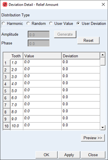
Figure 48 Deviation definition
For the options | Do the following |
|---|---|
Distribution Type | User can select between automatically generated Harmonic or Random distribution or manually paste distribution value or deviations by selecting User Value resp. User Deviation. |
Amplitude | This field sets the amplitude for the generated deviations of the Harmonic or Random distribution. |
Phase | This field sets the phase angle of the generated deviations for Harmonic distribution. The harmonic distribution is modeled using cosine function. |
Generate | By pushing generate button the predefined harmonic or random distribution is created and inserted into the deviation column of the table. |
Reset | By pushing reset the deviation distribution is set to zero for all teeth. |
Preview | You can preview the distribution deviation or value in the dedicated preview window. |
The distributions can be preview in dedicated preview windows as Value or Deviation, see Figure 49
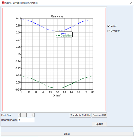
Figure 49 Distribution preview
Topology Export
You can export all applied microgeometry in form of lead, profile and flank reliefs to a text file with name cgp_name_microgeometry.txt by pressing the Export >> button on Modification tab. The data for left and right flank are exported separately. Additionally one can adjust the resolution for the underlying reference grid in the fields n_lead x n_profile. The underlying grid has the dimensions full_width x full_roll_length in model units, the topology is in micrometers. The values are separated by the space character. Negative values mean material is removed.
Deviations
You can define gear manufacturing errors to be considered in the contact simulation. Enter Runout Error for every tooth to describe deviations from ideal pitch circle or enter Cumulative Pitch Error for every tooth to describe deviations from ideal pitch, see Figure 51.
In case you don‘t have any measurement data You can also calculate harmonic distribution with cosine function by entering amplitude and phase shift, or apply generator of random numbers to get random distribution from interval of <-amplitude, +amplitude >. Positive value of Runout Error results in larger tooth radius and positive Pitch Error rotates tooth in counter clockwise direction according to the right hand rule. The Errors can be entered for each tooth flank individually. Both deviations represent the effect of non-uniform flank location on gear wheel, only one of their values should be applied, hence pitch error creates runout and vice versa. The Pitch Error is entered as arc length on circle with Measurement Diameter. This diameter is usually close to middle of active tooth flank height
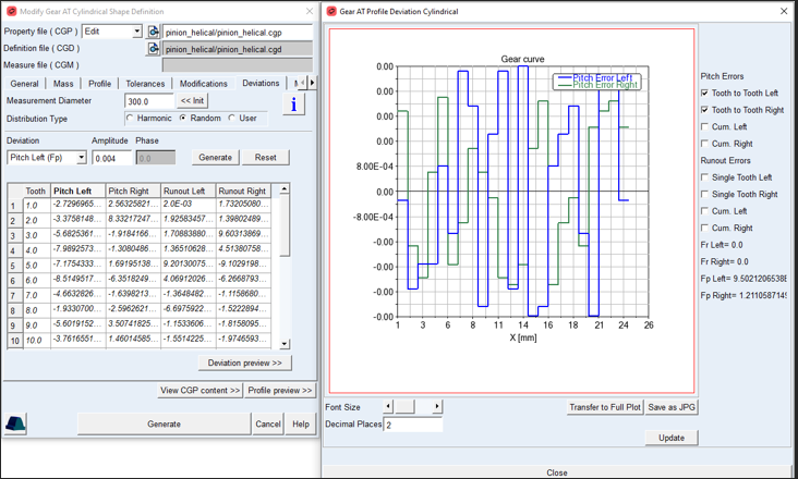
Figure 50 Shape Definition - Deviations tab and preview
You can display plot of error distributions as well as cumulative error by Deviations Preview button (Figure 50).
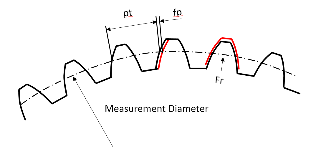
Figure 51 Pitch Deviation on Tooth and Runout at tooth
Measure
The measurement data stored in the cylindrical measure file (CGM) can be additionally adjusted to better match the true ideal flank proportions, which are usually defined in the second step in the Shape Definition dialog box.
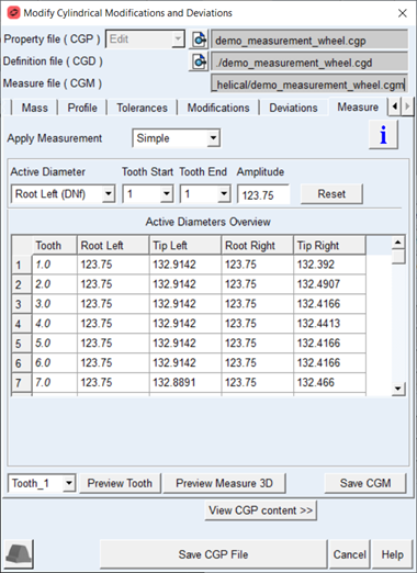
Figure 52 Shape Definition - Measure Tab
The Measure tab provides setting for active tip and root diameters and option to select from available measurement types stored in the Gear AT measure file (CGM) to be used in the simulation in the Apply Measurement option menu, see Figure 52. Measurement should ideally join the full tooth profile smoothly including all modifications like chamfer or undercut, so the adjustment of active tip and root diameters are available here for each tooth or averaged tooth in the table of active diameters. The relations between form and active diameters is visualized on Figure 53, the active diameters define the upper and lower boundary of measured data to be applied on the ideal contact surface, data is linearly extrapolated up to form diameters if required.
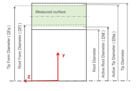
Figure 53 Diameters definition over measured Data
For the options | Do the following |
|---|---|
Apply Measurement | Diameter where the measurement for each profile is started. Usually it is close to the Root Form Diameter |
Active Diameter | Selects column to be set with amplitude field |
Tooth Start, Tooth End | Defines teeth range to be set by the amplitude field |
Amplitude | Sets the value of diameter over selected teeth range in the active diameter table. |
Root_left, Root_right, Tip_left, Tip_right | Diameter up to which the measurement data is applied to the tooth flank surface in the root area, resp. tip area. The initial value is determined automatically from the measured values of the defined profile. |
Save CGM | If you edit the Active diameters table, you can directly save just the CGM file pressing this button. If you do no save explicitly and you modified any active diameters the CGM file will be automatically updated as you save CGP file. |
The complete tooth contour created with the gear generator and the measured flank surface can be previewed for the selected tooth using the “Tooth preview" button, see Figure 55. The pure measurement data can be previewed for the selected tooth using the “Preview Measure 3D” button, see Figure 55. The data resolution for preview is fixed to the resolution defined in the Gear AT measure file ( CGM ).
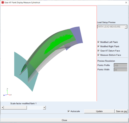
Figure 54 Tooth preview
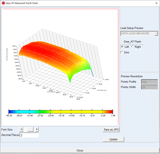
Figure 55 Measurement data preview
Activate Measured Contact Surface
You can select the real surface for contact simulation with Measured Flank toggle under Options card (see Figure 56) in Gear Element dialog box. Depending on the Apply Measurement option either Simple or Detailed measurement is applied on the flank surface.
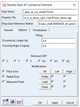
Figure 56 Option tab - Element dialog box