Gear AT Shape Definition
Gear AT Shape Definition allows you to create a property file (TLP) that defines the topology of a nut and spindle. Figure 313 shows how to access the tools you need to define your nut and spindle geometry.
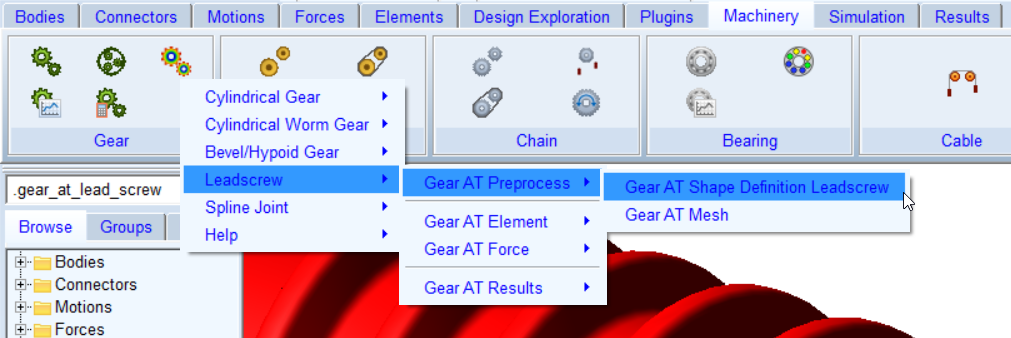
Figure 313 access to the Gear AT Shape Definition Leadscrew
The Gear AT Shape Definition has following tabs to help you design a gear
■Mass
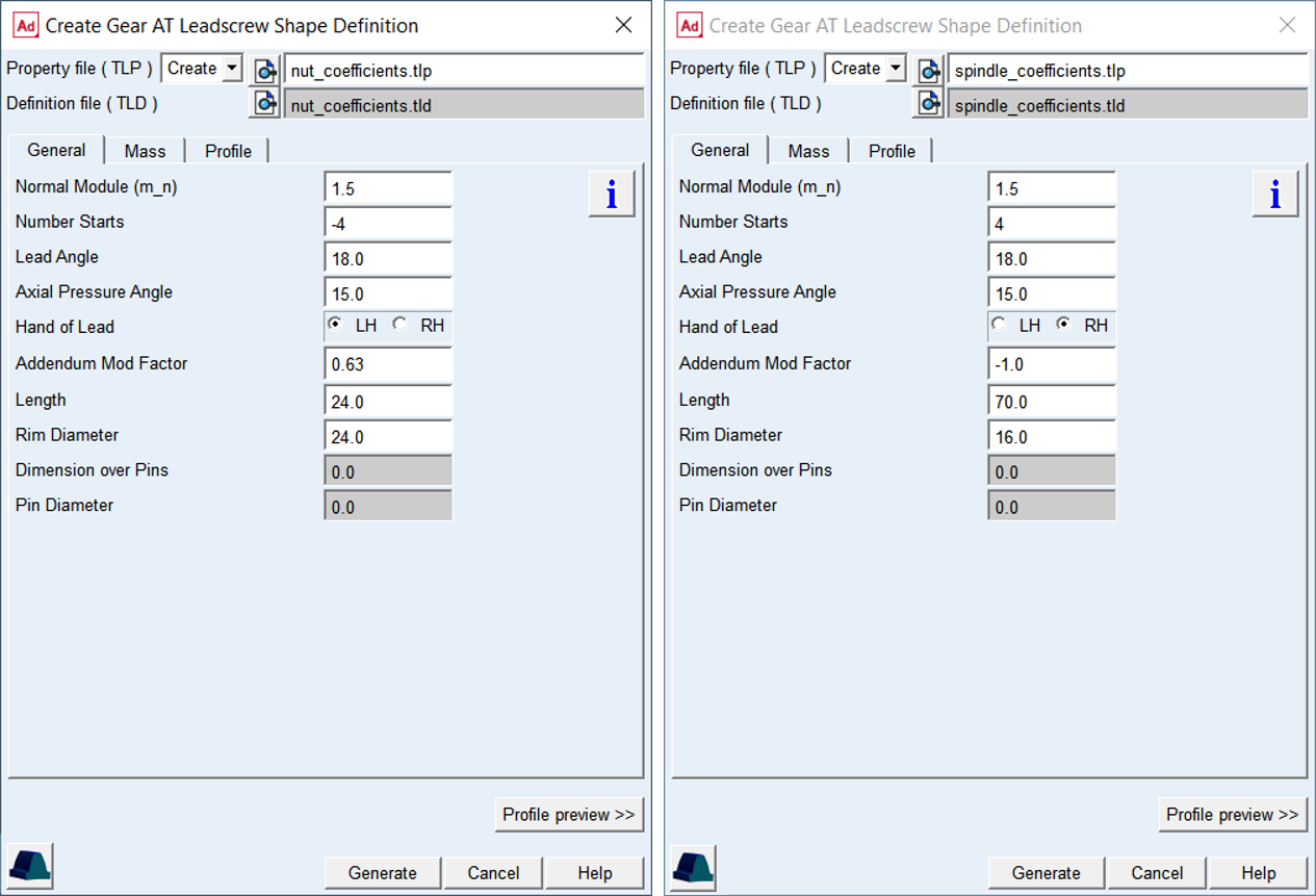
Figure 314 Nut and Spindle Shape Definition dialog box
Main
For the options | Do the following |
|---|---|
Property file ( TLP ) | In Create mode: ■Enter name of new nut or spindle property file. In Edit mode: ■Enter name of existing nut or spindle property file to edit parameters. |
Definition file (TLD) | Represents data sheet of a gear so it is summarize all basic geometrical data required to define profile. |
View Property or Definition File | Displays content of nut or spindle gear property file (*.TLP or *.TLD) in new information window. |
Create Mesh | Opens the mesh dialog box to proceed with Gear AT Mesh pre-processing for the current nut or spindle gear property file (*.TLP). |
Profile preview >> | Opens plot window and shows profile preview for the current set up of geometrical data entered in General and Profile tab. |
View TLP Content >> | You can view existing 2D profile of a thread, which is stored in property file already. This button is available in Edit mode only. |
General
For the options | Do the following |
|---|---|
Normal Module ( m_n ) | Value of module in normal plane of a thread. |
Number of Starts | A positive integer defines number of starts (threads) of a spindle while a negative integer a number of starts (threads) of a nut |
Lead Angle ( γ ) | Angle describing the thread or helix slope on pitch cylinder in respect to plane perpendicular to screw axis |
Axial Pressure Angle ( αx ) | The value corresponds to the haft of the screw thread angle. The angle is defined in axial plane |
Hand of Lead | Defines whether the helix is left handed (negative) or right handed (positive) |
Addendum Mod factor | This factor is positive when the reference profile is moved away from a screw axis by the amount of module * factor. Positive factor increases tooth thickness at reference circle while negative factor decreases. The sign of movement is reversed for internal screw resp. nuts |
Length (L) | Defines the length of spindle / nut on the pitch cylinder |
Rim Diameter | The rim diameter defines the boundary of the gear rim to the finite element model of the wheel body. |
Dimensions over Pins (MdK) | Defines the distance measured between pins / balls inserted into screw thread. The value has only informative character. |
Pin Diameter (DM) | Diameter of the measurement pin / ball. The value is used in the profile generator to calculate the Dimension over pins for comparison purposes |
The Normal Module and the Number of Starts are the fundamental variables in defining a gear; the module is often standardized.
Lead Angle
Angle describing the thread or helix slope on pitch cylinder in respect to plane perpendicular to screw axis, see Figure 315.
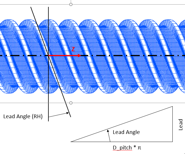
Figure 315 Definition of Lead Angle
Axial Pressure Angle
The value corresponds to the haft of the screw thread angle, see Figure 378. The angle is defined in axial plane.
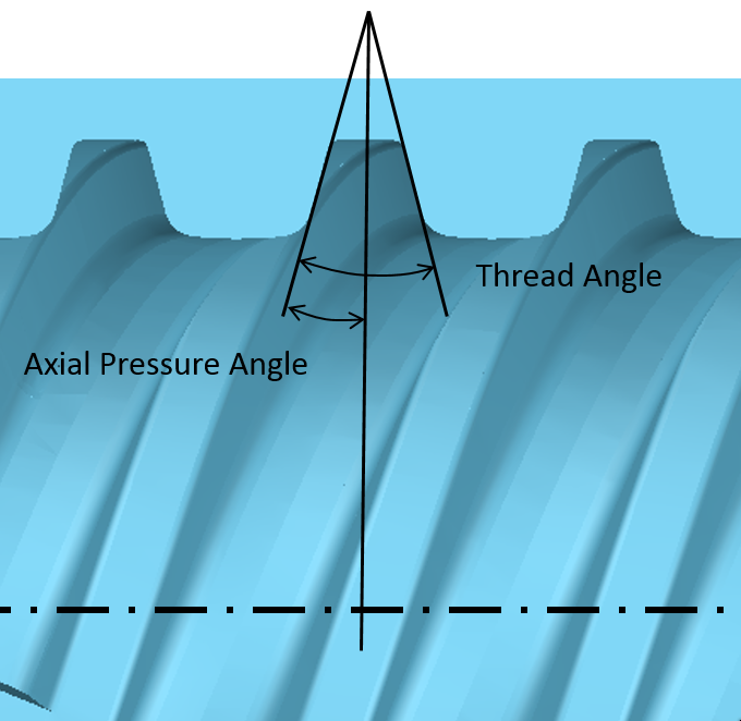
Figure 316 Definition of Axial Pressure Angle
Hand of Lead
Defines whether the helix is left handed (negative) or right handed (positive), Figure 315 shows right hand screw.
Length
Screw length defines the distance between transversal planes on each sides of screw thread, Figure 317.
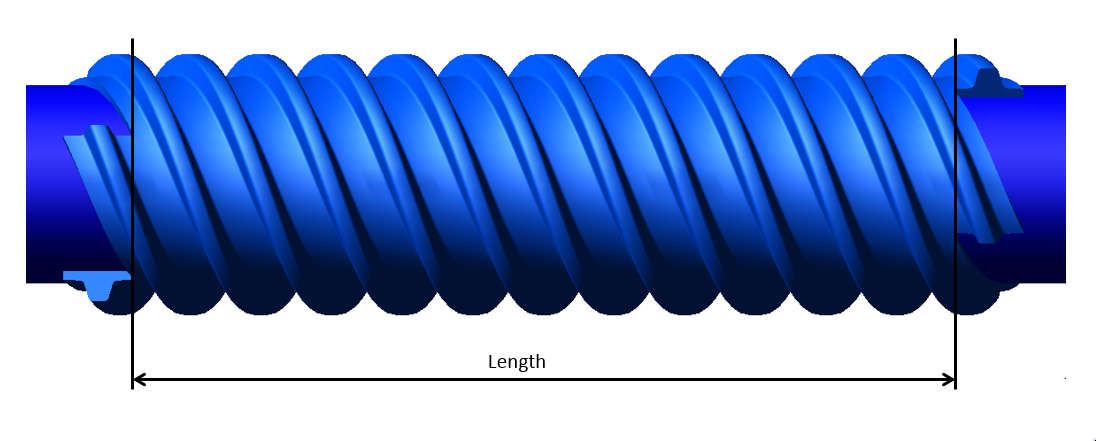
Figure 317 Definition of Screw Length
Rim Diameter
The rim diameter for an external gear and the bore diameter for an internal gear define the boundary of the gear rim (as solid and as finite element model) with the spindle nut body (Figure 318).
If bore or rim diameter are left to zero, the default is defined by Equation (5). Negative sign holds for external gear and positive sign holds for internal gear. However, the rim thickness should be in the range of (0.5, 1.5)m.
If user input is out of the range it is automatically adjusted and warning message is issued to the log file.

drim = droot +- m
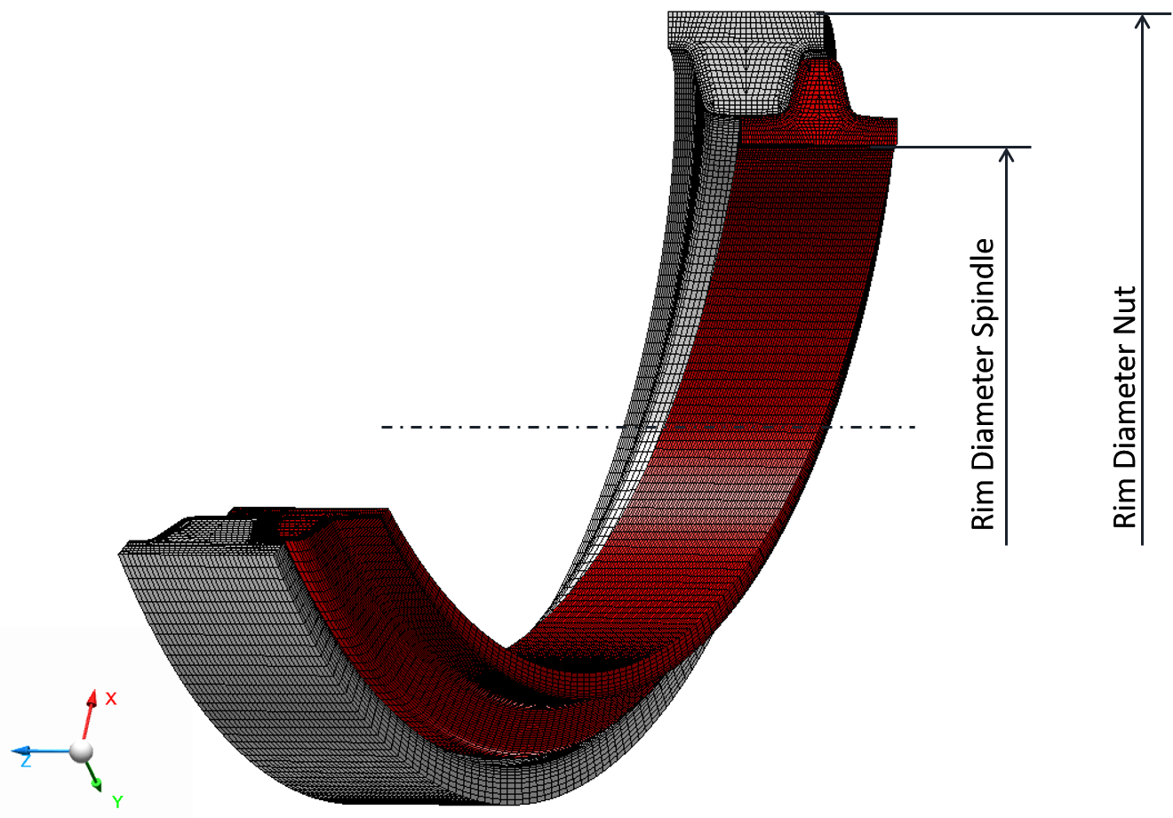
Figure 318 Rim Diameter
Hit the button to open info window with the content of current *.TLP property file. The Preview Profile>> button opens the Profile plot window for the current property file as shown in Figure 319.
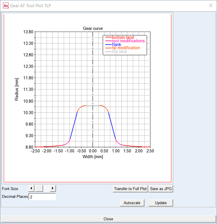
Figure 319 Profile plot
Mass
The Mass card of the Shape Definition process allows you to define the mass of the gear based either on the Geometry and Material Type or by specific User Input (Figure 320). In the former case the mass, center of mass and inertia tensor is computed later on by the mesher based on FE mesh volume. In the latter case enter all required data in current model units. In either case, inertia data are written to the *.TLP file.
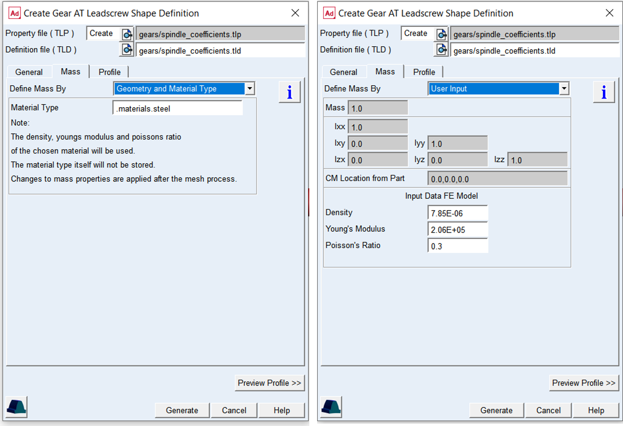
Figure 320 Mass and material properties
For the options | Do the following | |
|---|---|---|
Define Mass By | Set to: ■Geometry and Material Type ■User Input | |
For the option Define Mass By the Geometry and Material Type : | ||
Material Type | Choose material type either from predefined material library - right click the field and go to Material - Browse, or create a new one. Note that material of steel is set by default. | |
For the option Define Mass By the User Input : enter value of Mass, the principal mass moments of inertia (Ixx, Iyy, Izz) and cross-products of inertia (Ixy, Izx and Iyz). Note that you still need to define material parameters to define FE model of flexible tooth properly | ||
Mass | Enter the mass of the part. | |
Moments of inertia | Enter the mass moments of inertia. | |
CM Location from Part | Enter location vector of center of mass expressed in local part reference frame. | |
Density | Enter Material density to define Nastran MAT1 card of the flexible tooth for SOL101 and SOL103. The value is also used for calculation of the gear wheel inertia properties. | |
Young’s Modulus | The Young's modulus E is used to define Nastran MAT1 card of the flexible tooth for SOL101. It defines the relation between tensile strain ε and tensile stress ε by Hooke's law (Equation (6)), thus defining flexible tooth stiffness. For detailed information: see literature about theory of elasticity. | |
Poisson’s Ratio | The Poisson’s Ratio is used to define Nastran MAT1 card of the flexible tooth for SOL101. An extension εx of a linear elastic and isotropic material is accompanied by lateral strains εy and εz. Poisson's ratio ν defines this relation by Equation (7) and Equation (8) | |
Profile
The Profile tab defines the proportions of tooth profile which can be specified in axial plane. The profile parameters are defined in form of coefficient of Normal Modul. The Diameters informative fields show the resulting generating profile Proportions for quick check again data sheet values.

Figure 321 Profile tab and profile preview of Spindle threads
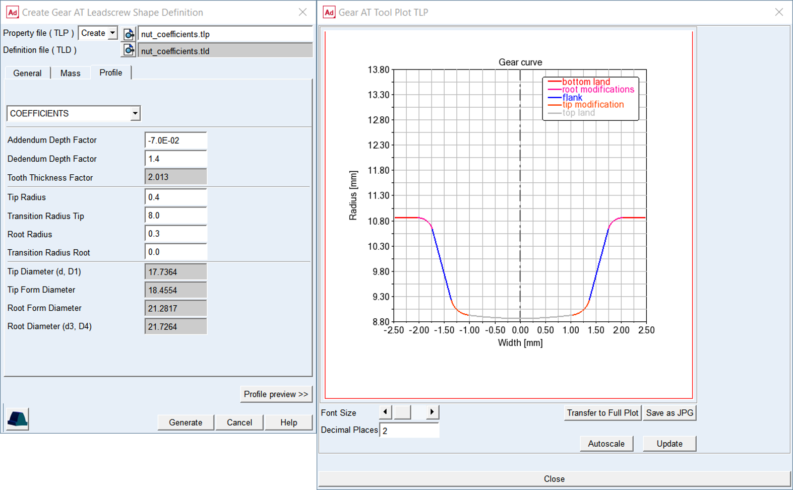
Figure 322 Profile tab and profile preview of nut threads (starts)
For the options | Do the following |
|---|---|
Addendum Depth Factor (h*aP) | The value defines addendum height of the gear tooth. This entry can be specified either in form of coefficient h*aP. Typical value is: h*aP = 1.0 |
Dedendum Depth Factor (h*fP) | The value defines the dedendum height of the gear tooth. This entry can be specified either in form of coefficient h*fP. Dedendum values usually includes tip clearance of 0.25 * normal module. Typical value is: h*fP = 1.25 |
Tooth Thicknes Factor (sp*) | The value has informative character for checking the tooth thickness in axial plane on reference cylinder. The value multiplied with Normal Modul gives axial tooth thickness sx = sp* x mn |
Addendum Mod Factor (x) | This factor is positive, when the reference profile is moved away from a screw axis by the amount of module * factor. Positive factor increases tooth thickness at reference circle while negative factor decreasee. The sign of movement is reversed for internal screw resp. nut |
Tip Radius (R1) | The value defines rounding section on a tip of a gear tooth |
Transition Radius tip (R1T) | The value defines rounding on tip usually between Tip Radius and Tip Diameter. The Tip Radius is smoothly connected to Transition Radius Tip. If the values is set to zero, no transition radius on tip is assumed |
Transition Radius Root (R2T) | The value defines rounding on root usually between Root Radius and Root Diameter. The Root Radius is smoothly connected to Transition Radius Root. If the values is set to zero, no transition radius on root is assumed |
Tip Diameter | The value represents the Tip resp. Major Diameter for Screw, it is calculated by profile generator and displayed for informative purposes |
Tip Form Diameter | This value represents the Tip Form Diameter for Screw, it is calculated by profile generator and displayed for informative purposes |
Root Form Diameter | This value represents the Root Form Diameter for Screw, it is calculated by profile generator and displayed for informative purposes |
Root Diameter | This value represents the Root resp. Major Diameter for Screw, it is calculated by profile generator and displayed for informative purposes |
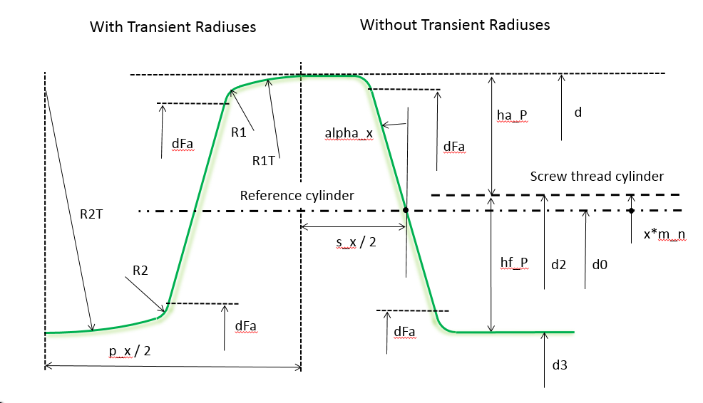
Figure 323 Leadscrew spindle profile definition
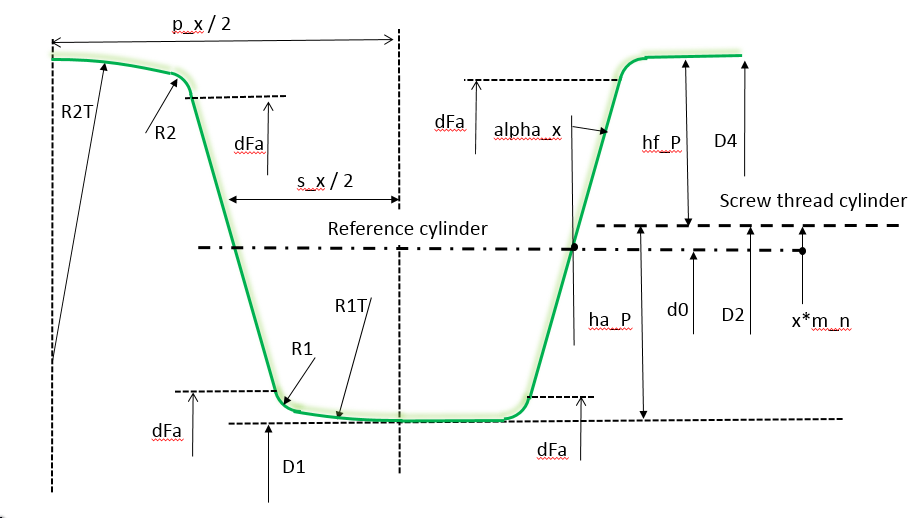
Figure 324 Leadscrew nut profile definition