Preprocess Needle Bearing FE mesh
Machinery → Bearing AT → Needle Bearing → Preprocessing → Mesh
Bearing AT has a built-in catalogue of many bearings, and after selecting any bearing based on the internal diameter, the macro-geometry of the selected bearing is automatically calculated.
In Create mode you define a new property file by selecting one of available bearings from catalogue and calculating the macro-geometry by using Compute geometry button. This can be also done by entering the basic bearing dimensions (inner diameter, outer diameter, bearing width) and the static load rating.
In Edit mode is possible to load already existing property file and change the macro-geometric parameters of the bearings manually. How to proceed not only in the Edit mode case, is explained in the following steps in Bearing AT Online Help. Meaning of all required input parameters is explained below.
In both modes, it is possible to make a preview of bearing macro-geometry. There are also sketches, which show the meaning of each macro-geometry parameter.
This dialog box allows you to create needle roller bearing property file (*.npf) or modify existing one. There are geometrical data of the bearing stored in this file. This preprocessing step will automatically generate FE meshes of bearing inner and outer ring and rolling element and submit Nastran computation (SOL101) which provides intermediate results (*.PCH) required for contact preprocessing.
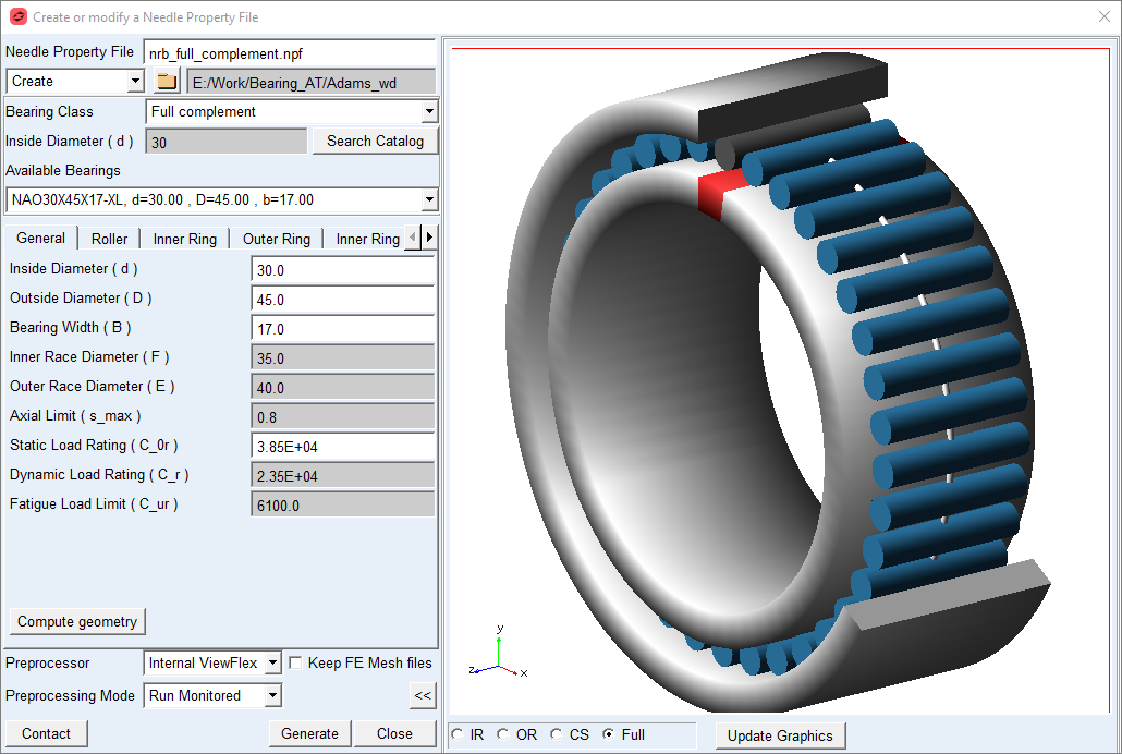
Figure 83 Needle roller bearing geometry preview
Main
For the options | Do the following |
|---|---|
Needle Property File | Enter the name or browse for the needle bearing property file (*.npf). It contains input for geometry and material data. |
Create/Edit mode | Choose one of the options. In Create mode you can choose from a wide range of catalogue bearings. In Edit mode you can load existing *.npf file and adjust bearing macro-geometrical parameters. |
Destination folder | It is possible to select the destination folder for saving the property files via the button with the folder icon |
Bearing Class | Select from available classes: ■Full complement – consists of inner ring, rollers with cage assembly and outer ring ■Rollers and cage assemblies – a role of inner ring is taken by shaft and role of outer ring by bore body (housing or wheel body) ■Without inner ring – consists of rollers with cage assembly and outer ring; a role of inner ring is taken by shaft Note: In order to make contact preprocessing possible, each bearing class requires to have both, inner and outer ring defined |
Inside Diameter (d) | Enter the required inside diameter of the bearing |
Search Catalogue | Click on this button after the inside diameter of the bearing has already been entered |
Available Bearings | From option menu select one of required bearings |
Compute geometry | Click on Compute geometry button - all required values in all tabs will be calculated |
Preview >> | Show preview of bearing geometry after filling all parameters (Figure 83) |
Preprocessor | Select one of following options. ■External ViewFlex: use this option when there is no Nastran installation available. On background there is SOL101 running by Adams embedded Nastran Solver ■External Nastran: use this option when you have Nastran installation available. This option allows you to continue working since standalone Nastran is executed in external shell window hence the main window remains active. Please note that additional Nastran license is required. It makes use of Nastran SMP license if available. This option is not available on linux ■Internal Nastran: use this option when you have Nastran installation available. It makes use of Nastran SMP license if available ■Mesher Only: use this option to verify that FE Mesh is valid before running SOL101 |
Preprocessing Mode | Select one of following options for running mesh pre-processor. ■Run Quiet: executes mesher without any output to the screen ■Run Monitored: executes mesher with output to the screen ■Files Only: the batch file is created but not submitted to execution, one has to launch it manually |
Contact | Open contact preprocessing dialog box after FE meshes are created and Nastran SOL101 is completed (Preprocess Needle Bearing Contact) |
Roller
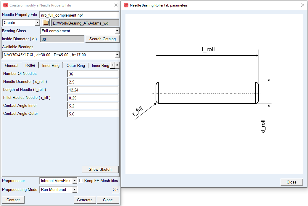
Figure 84 Roller tab and geometry
For the options | Do the following |
|---|---|
Number of Needles | Enter the number of needles in bearing assembly |
Needle Diameter ( d_roll ) | Enter value of needle diameter |
Length of Needle ( l_roll ) | Enter value of needle length It defines the total length of the roller along its rotational axis. |
Fillet Radius Needle ( r_fill ) | Enter value of needle fillet radius |
Contact Angle Inner | Enter the value of contact angle inner (  ) measured on roller. It represents the angle of contact between rolling element and inner ring under ultimate bearing load measured around rolling element rotational axis in normal plane (XY) of bearing, see Figure 85. ) measured on roller. It represents the angle of contact between rolling element and inner ring under ultimate bearing load measured around rolling element rotational axis in normal plane (XY) of bearing, see Figure 85. |
Contact Angle Outer | Enter the contact angle outer (  ) measured on roller. It represents the angle of contact between rolling element and outer ring under ultimate bearing load measured around rolling element rotational axis in normal plane (XY) of bearing, see Figure 85. ) measured on roller. It represents the angle of contact between rolling element and outer ring under ultimate bearing load measured around rolling element rotational axis in normal plane (XY) of bearing, see Figure 85. |
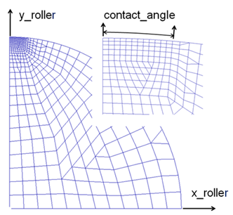
Figure 85 Needle contact angle
Inner Ring
Define dimensions of inner ring geometry. In order to make contact preprocessing possible, each bearing class requires to have inner ring defined. In case of Rollers and cage assemblies or Without inner ring bearing class a rolling element makes contact pair with shaft part, which is for the purpose of contact computation in Bearing AT represented by inner ring geometry defined in the Inner Ring tab of the dialog box. Neither inner ring geometry nor inertia will be applied in Adams model once a bearing element is created with previously mentioned bearing classes.
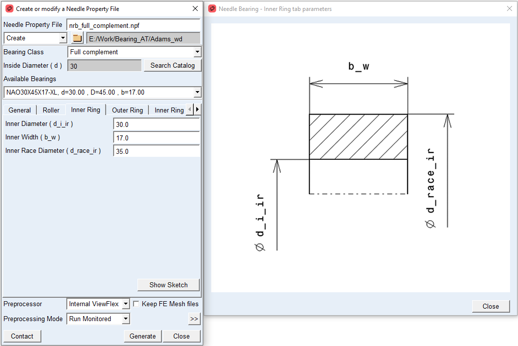
Figure 86 Inner ring tab and geometry
For the options | Do the following |
|---|---|
Inner Diameter ( d_i_ir ) | Enter the inner diameter of inner ring. It represents bearing inside diameter in case of Full complement bearing class and shaft bore diameter in case of Rollers and cage assemblies or Without inner ring bearing class. |
Inner Width ( b_w ) | Enter value of inner ring width. |
Inner Race Diameter ( d_race_ir ) | Enter value of inner ring race diameter. It represents the contact surface with rolling element, hence the inside diameter in case of Rollers and cage assemblies or Without inner ring bearing class. |
Outer Ring
Define dimensions of outer ring geometry. In order to make contact preprocessing possible, each bearing class requires to have outer ring defined. In case of Rollers and cage assemblies bearing class a rolling element makes contact pair with block (housing) part, which is for the purpose of contact computation in Bearing AT represented by outer ring geometry defined in the Outer Ring tab of the dialog box. Neither outer ring geometry nor inertia will be applied in Adams model once a bearing element is created with previously mentioned bearing class.
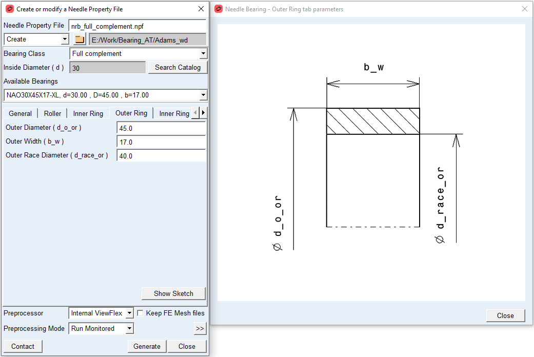
Figure 87 Outer ring tab and geometry
For the options | Do the following |
|---|---|
Outer Diameter ( d_o_or ) | Enter the outer diameter of outer ring. It represents bearing outside diameter in case of Full complement or Without inner ring bearing class and block (housing) outer diameter in case of Rollers and cage assemblies bearing class. |
Outer Width ( b_w ) | Enter the outer ring width. |
Outer Race Diameter ( d_race_or ) | Enter value of outer ring race diameter. It represents the contact surface with rolling element, hence the outside diameter in case of Rollers and cage assemblies bearing class. |
Inner and Outer Ring Mass
The Inner Ring Mass and Outer Ring Mass card allows you to define the mass of the inner and outer ring, respectively, based on the Geometry and Material Type or by specific User Input. In the former case the mass, center of mass and inertia tensor is computed later by the mesher based on FE mesh volume. In the latter case enter all required data in current model units. In either case, inertia data are written to the *.npf file and applied to the bearing element when created.
Note: | In case of Rollers and cage assemblies bearing class the inertia properties will be set to zero values for both, the inner and outer ring and in case of Without inner ring bearing class the zero inertia values will be set for inner ring part once a bearing element is created in Adams. |
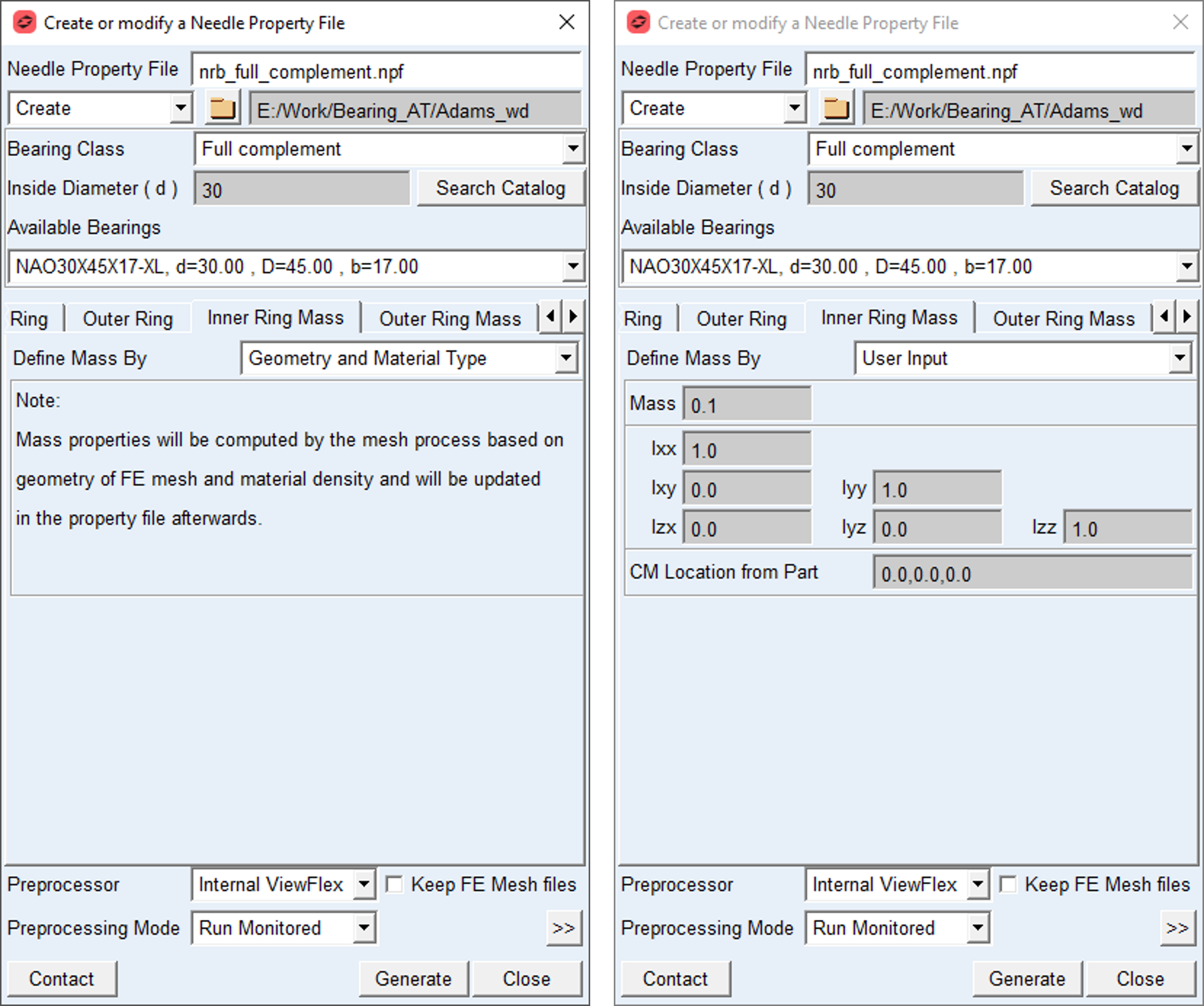
Figure 88 Mass tab for Inner Ring
For the options | Do the following |
|---|---|
Define Mass by | Set to one of following options: ■Geometry and Material Type ■User input |
For the option Define Mass by the Geometry and Material Type: Mass properties of a ring will be computed by the mesh process based on a ring geometry FE mesh and material density entered in the Material Data tab and will be updated in the property file data block. | |
For the option Define Mass by the User Input: Enter value of Mass, the principal mass moments of inertia (lxx, lyy, lzz) and cross-products of inertia (lxy, lzx, lyz) in model units. Note: You still need to define material parameters in the Material Data tab to define FE model of bearing properly. | |
Mass | Enter the mass of the part. |
Moments of inertia | Enter values of the bearing ring mass moments of inertia tensor expressed in local part reference frame (bearing reference marker). |
CM Location from Part | Enter location vector of center of mass expressed in local part reference frame (bearing reference marker). |
Material Data
You can define different materials for rolling elements, inner ring and outer ring. When defining via the Material Type option, you can use predefined materials from the library, or you can create a new one. Using the User input option, it is necessary to enter values of Young’s Modulus, Poisson’s Ratio and Density appropriate for the material you require.
Note: | In either case the Young’s Modulus, Poisson’s Ratio and density of chosen material will be stored in the property file. |
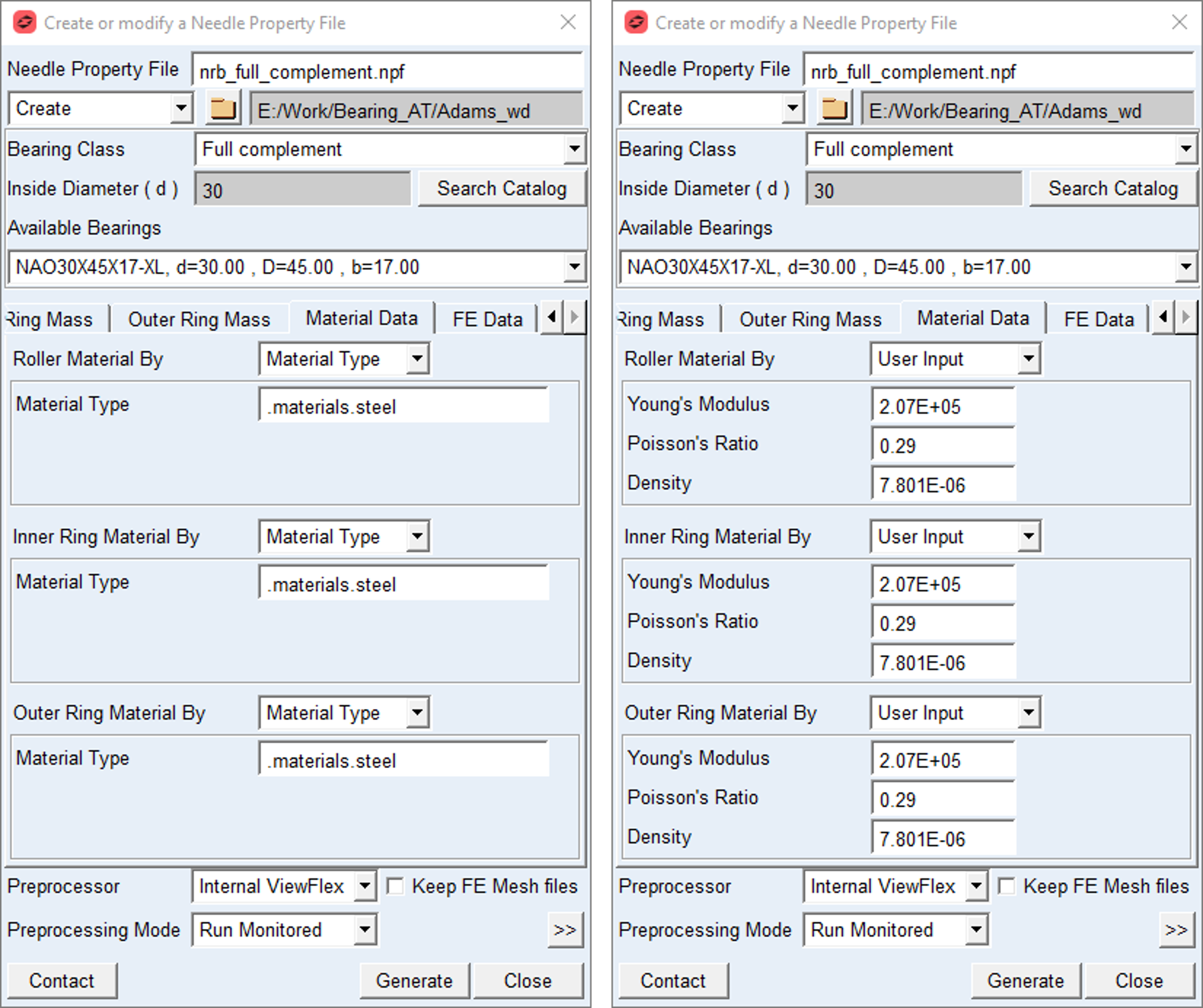
Figure 89 Material Data tab
For the options | Do the following |
|---|---|
Define Mass by | Set to: ■Material Type ■User input |
For the option Roller / Inner Ring / Outer Ring Material by the Material Type: | |
Material Type | Choose material type either from predefined material library - right click the field and go to Material → Browse or create a new one. Note: Material of steel is set by default |
For the option Roller / Inner Ring / Outer Ring Material by the User Input: Enter value of Young’s Modulus, Poisson’s Ratio and Density appropriate for the material you require | |
Young’s Modulus | Enter Young‘s Modulus value of the bearing material. It defines the relation between tensile strain e and tensile stress S by Hooke’s law; see equation below. For more detailed information: see literature about ‘theory of elasticity’ S = E * e Young's modulus for steel is around 2.1E5 N/mm2 |
Poisson’s Ratio | Enter Poisson's Ratio value of bearing material An extension ex of a linear elastic material is accompanied by lateral strains ey and ez. Poisson's ratio defines this relation by following equations ey = - ν* ( ex / E ) ez = - ν* ( ex / E ) Poisson's ratio can also be derived from the shear modulus G, please look at the literature for more details. G = E / ( 2 * ( 1 + ν) ) Poisson's ratio for steel is around 0.3. |
Mass Density | Enter Mass Density value of bearing material The mass m of a solid body is computed from its volume V multiplied by the Mass Density rho. m = V * rho Mass Density for steel is around 7.8E-6 kg/mm3 |
FE Data
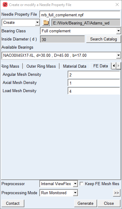
Figure 90 FE Data tab
For the options | Do the following |
|---|---|
Angular Mesh Density | Enter value of Angular Mesh Density Angular Mesh Density (supported values are 1 to 6) defines the number of elements along the Contact Angle of the roller (Figure 85). The values of 1 to 6 correspond to 10, 12, 14, 16, 18 and 20 elements. A higher value will result in a finer FE-mesh. Inner and outer ring have the same Angular Mesh Density. Default = 2.0 |
Axial Mesh Density | Enter value of Axial Mesh Density Axial Mesh Density controls the approximate number of elements in axial direction of the contact surface of the roller; supported values are 1 to 5. A low value means a low number of elements in axial direction. The element length in axial roller direction is a multiple of the element length in tangential direction (see Contact Angle and Angular Mesh Density); the multiplication factor decreases with increasing Axial Mesh Density. Default = 2.0 |
Load Mesh Density | Enter value of Load Mesh Density Load Mesh Density controls the fineness of the contact computations, what influences the CPU-time for the FEA-analysis and for the compliance analysis. Supported input values are 1 to 5. A high value of load mesh density means more finite elements per load element in axial direction. Default = 3.0 |