Requests
Some of the results are reported in the so-called contact coordinate system (CCS). Each gear pair has such coordinate system as shown in Figure 123. The origin of the CCS is located at the reference marker of Gear 1 (w1). The Z-axis of the CCS is identical with the Z-axis of Gear 1. The X-axis and Y-axis of the CCS lie in the plane normal to the Z-axis at the center of Gear 1. The projection of the vector from Gear 1 center to Gear 2 (w2) center on the normal plane gives the Y-axis of the CCS. The X-axis of the CCS follows from the right hand rule.
It is assumed, that no more than 5 teeth are in contact.
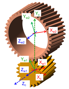
Figure 123 Contact coordinate system
There are following request groups and underlying requests for Standard option of the Flexible Tooth and Full Flex Gear:
■Additional_Output_Files
■CGR_Output
■Contact
■Tooth_xx_Max_Pressure
■Tooth_xx_KH_Beta
■Tooth_xx_KF_Beta
■Damping
■FX, FY, FZ_Gear_1_Viscous
■TX, TY, TZ_Gear_1_Viscous
■Transition_TZ
■Transition_Delta_WZ
■Gear_def_Tooth_0 (Full Flex Gear only)
■Tan, Rad, Axi_tdef_Gear_1
■AX, AY, AZ_adef_Gear_1
■Tan, Rad, Axi_tdef_Gear_2
■AX, AY, AZ_adef_Gear_2
■Kinematics
■Distance_Radial
■Distance_Axial
■Misalignment_Lateral
■Misalignment_Radial
■Misalignment_Magnitude
■Gear_1_TE_Angle
■Gear_2_TE_Angle
■Gear_1_TE_Length
■Gear_2_TE_Length
■Power Loss
■Friction
■Structural_Damping
■Hydrodynamic_Damping
■Total
■Power_Gear_1
■Power_Gear_2
■Efficiency
■Total Force and Torque
■FX, FY, FZ_Gear_1
■TX, TY, TZ_Gear_1
■FX, FY, FZ_Gear_2
■TX, TY, TZ_Gear_2
■Tooth_xx
There are following request groups and underlying requests for Enhanced option of the Flexible Tooth and Full Flex Gear:
■Additional_Output_Files
■CGR_Output
■Contact
■Tooth_xx_Min_Gap
■Damping
■FX, FY, FZ_Gear_1_Structure
■TX, TY, TZ_Gear_1_Structure
■Tooth_xx_Squeeze_Vel
■Tooth_xx_Viscous_FM
■Friction
■FX, FY, FZ_Gear_1
■TX, TY, TZ_Gear_1
■Tooth_xx_Sliding_Vel
■Tooth_xx_Fm_Frict
■Tooth_xx_Tz_Frict
■Gear_def_Tooth_0 (Full Flex Gear only)
■Tan, Rad, Axi_tdef_Gear_1
■AX, AY, AZ_adef_Gear_1
■Tan, Rad, Axi_tdef_Gear_2
■AX, AY, AZ_adef_Gear_2
■Kinematics
■Contact_Tooth_Gear_1
■Contact_Tooth_Gear_2
■Gear_1_WZ
■Gear_2_WZ
■Stiffness
■FX, FY, FZ_Gear_1
■TX, TY, TZ_Gear_1
■Tooth_xx_Max_Penetration
■Wearing
■Tooth_xx_Min_Oil_Film_Thick
■Tooth_xx_Max_fric_power
There are following request groups and underlying requests for Standard option of the Gear Fast:
■Contact
■Tooth_xx_Max_Pressure
■Damping
■FX, FY, FZ_Gear_1_Viscous
■TX, TY, TZ_Gear_1_Viscous
■Transition_TZ
■Transition_Delta_WZ
■Kinematics
■Distance_Radial
■Distance_Axial
■Misalignment_Lateral
■Misalignment_Radial
■Misalignment_Magnitude
■Gear_1_TE_Angle
■Gear_2_TE_Angle
■Gear_1_TE_Length
■Gear_2_TE_Length
■DY_pert_norm
■DZ_pert_norm
■AX_pert_norm
■AY_pert_norm
■AZ_pert_norm
■TZ_pert_norm
■Total Force and Torque
■FX, FY, FZ_Gear_1
■TX, TY, TZ_Gear_1
■Tooth_xx
There are following request groups and underlying requests for Enhanced option of the Gear Fast:
■Contact
■Min_Gap
■PlusMinus
■Damping
■FX, FY, FZ_Gear_1_Structure
■TX, TY, TZ_Gear_1_Structure
■Squeeze_Vel
■Kinematics
■Gear_1_WZ
■Gear_2_WZ
■Friction
■FX, FY, FZ_Gear_1
■TX, TY, TZ_Gear_1
■Tooth_xx_Sliding_Vel
■Friction_Power_Loss
■Stiffness
■FX, FY, FZ_Gear_1
■TX, TY, TZ_Gear_1
Extended definition:
The result of Contact_Tooth_Gear_1 and Contact_Tooth_Gear_2 is explained on Figure 124. If the right flank is in contact, the tooth number is displayed as negative number.
The result of Distance_Radial, Distance_Axial, Misalignment_Lateral, Misalignment_Radial, Misalignment_Magnitude gives the position and the rotation around the X-axis and Y-axis of wheel_2 relative to wheel_1 in the CCS.
The result of Tooth_xx_Max_Penetration helps to evaluate the selected contact stiffness for rigid body contact. In case of a flexible tooth, only a small penetration should be reported under normal operating conditions. The tooth_0 is the tooth in the middle of the rim of wheel 1 with the smallest deviation to the YZ-plane of the CCS. The relative teeth numbers -2 to +2 (M2, M1, 0, P1, P2) follow the rule of right hand when the thumb points in wheel_1 Z-axis direction; see Figure 124 for the definition of the contact tooth and for gear teeth numbering convention.
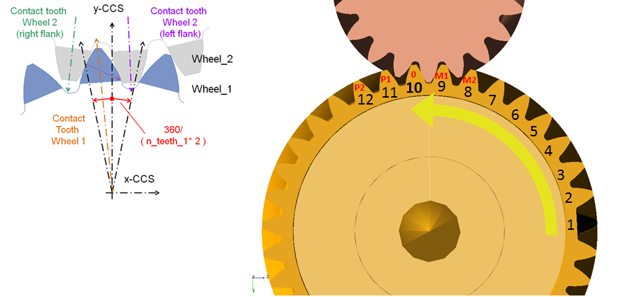
Figure 124 Contact tooth and numbering convention
The resulting force and torque vectors are measured in the CCS applied on wheel 1 are given by FX, FY, FZ_Gear_1 and TX, TY, TZ_Gear_1. The corresponding force and torque vectors applied on wheel 2 can be plotted as FX, FY, FZ_Gear_2 and TX, TY, TZ_Gear_2. The resulting force and torque vectors including all components from contact, damping and friction are located in the Total Force and Torque group.
The result of Tooth_xx_Sliding_Vel expresses the maximum magnitude of sliding velocity vector over the tooth contact area. The negative sign indicates that teeth are meshing in the approach portion of the line of action while positive sign indicates the teeth are meshing in the recess portion. This sign convention also holds for the results of the friction force magnitude per tooth Tooth_xx_Fm_Frict and friction torque magnitude per tooth Tooth_xx_Tz_Frict. The sign of the friction force (torque) magnitude acting on a tooth during approach action is negative because it opposes the torque exerted by the working force vector; so it opposes, rather than helps the action. During recess, the friction force (torque) vector is in the same direction as the torque exerted by the working force, aiding the rotation of the gear wheel.
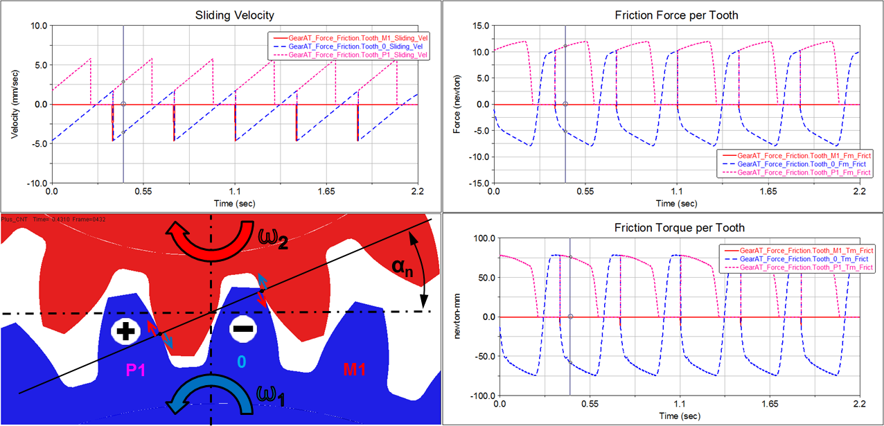
Figure 125 Sliding velocity, Friction Force and Torque sign convention
Results of Transition_TZ and Transition_Delta_WZ should help to set the damping ratio and end time for the damping as described in Gear AT Force.
Result of transmission error (TE) in general expresses the difference between ideal and actual gear ratio of the gear pair. The TE value can be calculated in angular units or length units and typically for output wheel of a gear pair. The TE would be zero for geometrically ideal involute profiles and rigid gear wheels.
Figure 126 Transmission Error
In case of angular unit, one can express the value as output wheel angle – ideal output wheel angle. The value is calculated for gear wheels of a gear pair by Equation (35) and Equation (36) and can be found labeled as Gear_1_TE_Angle and Gear_2_TE_Angle. Phi means rotation angle.
 | (35) |
 | (36) |
In case of length unit, the value is expressed as length over line of action. Benefit of TE in length units is, the value has identical amplitude regardless which gear wheel is taken as reference. The value is calculated for gear wheels of a gear pair by Equation (37) and Equation (38) and can be found labeled as Gear_1_TE_Length and Gear_ 2_TE_Length.
 | (37) |
 | (38) |
Following results of Full Flex Gear element comprised in the Gear_def_Tooth_0 results group represent deformation of flexible wheel body under the middle tooth in contact. Translational deformations refer to the radial and tangential axes layed over the center of contact area of tooth_0 - Figure 127 - whereas angular deformations refer to X-axis, Y-axis and Z-axis of the contact coordinate system (CCS).
Tan_tdef_Gear_1 / Gear_2 - translational deformation of Tooth_0 along tangential direction
Rad_tdef_Gear_1 / Gear_2 - translational deformation of Tooth_0 along radial direction
Axi_tdef_Gear_1 / Gear_2 - translational deformation of Tooth_0 along axial direction (Z-axis of CCS)
AX_adef_Gear_1 / Gear_2 - angular deformation of Tooth_0 about X-axis of CCS
AY_adef_Gear_1 / Gear_2 - angular deformation of Tooth_0 about Y-axis of CCS
AZ_adef_Gear_1 / Gear_2 - angular deformation of Tooth_0 about Z-axis of CCS
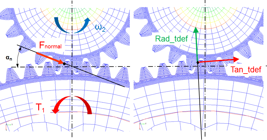
Figure 127 Tooth_0 deformation of flexible wheel body
The Figure 128 and Figure 129 shows results of tangential and radial deformation of light-weight flexible wheel body. It depicts correlation of extreme values of deformation to the location of holes.
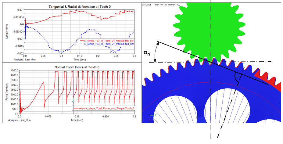
Figure 128 Maximum tangential deformation of flexible wheel body
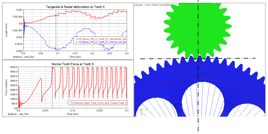
Figure 129 Maximum radial deformation of flexible wheel body
Following results of Gear FAST comprised in the results group Kinematics are of special importance. The first 5 results represent normalized translational and rotational displacements and the 6th component shows the normalized perturbation due to torque loading. These requests informs you if the model still operates in valid range of generated data stored in *.cgf file.
DY_pert_norm - normalized radial perturbation, allowed range < -1.0 , +1.0 >
DZ_pert_norm - normalized axial perturbation, allowed range < -1.0 , +1.0 >
AX_pert_norm - normalized lateral misalignment perturbation, allowed range < -1.0 , +1.0 >
AY_pert_norm - normalized radial perturbation, allowed range < -1.0 , +1.0 >
AZ_pert_norm - normalized angular position perturbation, allowed range < -0.5 , +0.5 >
where :
AZ_pert_norm = 0.0: neutral position
AZ_pert_norm = -0.5: starting position
AZ_pert_norm = 0.5: ending position
TZ_pert_norm - normalized torque perturbation, allowed range < -1.0 , +1.0 >
PlusMinus - indicates plus (left) or minus (right) flank is in contact