SECTION
The SECTION statement defines section properties at a node on an FE_PART. The supported TYPES of SECTION are rectangular, ellipse, circular, beam, properties and generic.
The SECTION statement is ignored by solver and is used by Adams View to restore SECTION data in an Adams View session. This is because the FE_PART statement, itself, directly stores each node's area and area inertia information (which is, of course, derived from the sections created in Adams View and assigned there to each node).
Format
Arguments
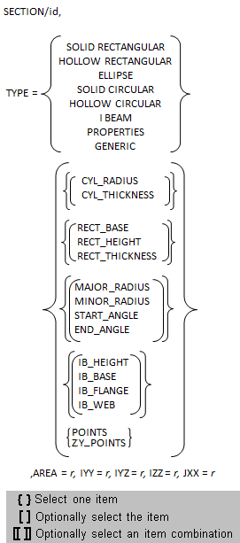
TYPE | Specifies the type (string, shown in above format) of the section to be created. ■SOLID RECTANGULAR ■HOLLOW RECTANGULAR ■ELLIPSE ■SOLID CIRCULAR ■HOLLOW CIRCULAR ■I BEAM ■PROPERTIES: No geometry is supported, only AREA, IYY, IYZ, IZZ, JXX are needed. ■GENERIC: Cross-section geometry is defined by the set of points specified by the POINTS argument. |
CYL_RADIUS | Specifies the radius of the cylinder if the section is cylindrical in nature. |
CYL_THICKNESS | Specifies the thickness of the cylinder if the section is cylindrical in nature and is hollow. |
RECT_BASE | Specifies the base of the rectangle if the section is rectangular in nature. |
RECT_HEIGHT | Specifies the height of the rectangle if the section is rectangular in nature. |
RECT_THICKNESS | Specifies the thickness of the rectangle if the section is rectangular and hollow in nature. |
MAJOR_RADIUS | Specifies the major radius of the ellipse if the section is elliptical in nature. |
MINOR_RADIUS | Specifies the minor radius of the ellipse if the section is elliptical in nature. |
START_ANGLE | Specifies the start angle of the ellipse if the section is elliptical in nature. |
END_ANGLE | Specifies the start angle of the ellipse if the section is elliptical in nature. |
IB_HEIGHT | Specifies the height of the beam if the section is in the form of a beam. |
IB_BASE | Specifies the base dimension of the beam if the section is in the form of a beam. |
IB_FLANGE | Specifies the flange of the beam if the section is in the form of a beam. |
IB_WEB | Specifies the web of the beam if the section is in the form of a beam. |
POINTS | Specifies the location of the series of points defining the generic cross section in an x-y plane. Because the local cross sectional plane of an FE Part is expressed in local z-y coordinates, we no longer recommend using this option. Instead use the ZY_POINTS option. Existing datasets that make use of the POINTS argument will continue to be supported but in the interactive section editor dialog they will be mapped to the equivalent ZY_POINTS and displayed that way. Furthermore, subsequent adm file export actions will convert to an equivalent ZY_POINTS argument. 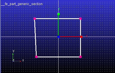 |
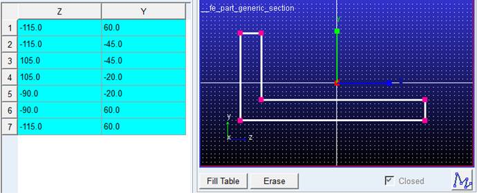
ZY_POINTS | Specifies the location of the series of points defining the generic cross section. Syntax: z1, y1, z2, y2 and so on. Z, Y points of section drawn on grid. 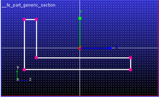 |
AREA | Specifies the cross-section area of the section. |
IYY | Specifies the moment of inertia about the Y axis. Defaults to 1.0. |
IYZ | Specifies the product of inertia with respect to the Y and Z axes. Default value is 10. |
IZZ | Specifies the moment of inertia about the Z axis. Defaults to 1.0. |
JXX | Specifies the torsional constant. It is the torsional constant which is used to assemble the torsional equation of motion describing the ability to resist torque. |
Extended definition for sections
1. Example - SOLID RECTANGULAR
A distributed-mass beam is shown in Figure 22 below. For this case, just two nodes are enough to model the beam.
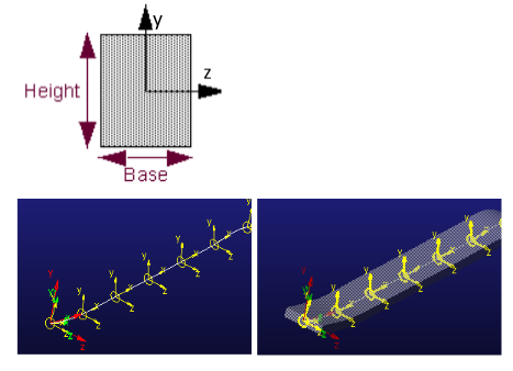
Figure 22 RECTANGULAR SECTION
!----------------------- SECTIONS -----------------------------------
!
! adams_view_name='SECTION_2'
SECTION/2
, TYPE = SOLID RECTANGULAR
, RECT_BASE = 15
, RECT_HEIGHT = 10
, IYY = 2812.5
, IZZ = 1250
, IYZ = 0
, JXX = 2934.567901
, AREA = 150
2. Example - I-BEAM
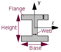
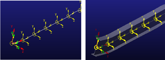
Figure 23 I-BEAM
SECTION/4
, TYPE = I BEAM
, IB_HEIGHT = 50
, IB_BASE = 25
, IB_FLANGE = 5
, IB_WEB = 5
, IYY = 13437.5
, IZZ = 1.5375E+005
, IYZ = 0
, JXX = 3958.333333
, AREA = 450
3. Example - ELLIPSE
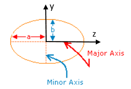
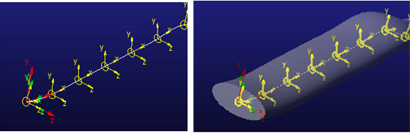
Figure 24 ELLIPSE
SECTION/6
, TYPE = ELLIPSE
, MAJOR_RADIUS = 100
, MINOR_RADIUS = 50
, START_ANGLE = 0D
, END_ANGLE = 360D
, IYY = 3.926990817E+007
, IZZ = 9.817477042E+006
, IYZ = 0
, JXX = 3.141592654E+007
, AREA = 15707.96327
For more information refer the Create Section dialog box.
4. Example - GENERIC
User can create a cross-section of choice by using Generic Section supported for FE Part.
Points for cross-section are the input for Section definition.
! adams_view_name='SECTION_1'
SECTION/1
, TYPE = Generic
, ZY_POINTS = -115, 60, -115, -45, 105, -45, 105, -20, -90, -20, -90, 60, -115
, 60
, IYY = 4.34375E+007
, IZZ = 7.9625E+006
, IYZ = -3.20625E+006
, JXX = 10
, AREA = 7500
!
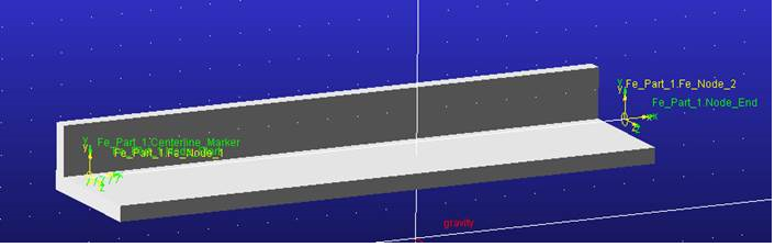
Figure 25 GENERIC
Example of drawing a section on grid: