FIELD
The FIELD statement applies a translational and rotational action-reaction force between two markers.
Format
Arguments
CMATRIX=r1,...,r36 | Defines a 6x6 matrix of viscous damping coefficients. The following matrix shows the values to input.  Enter the elements by columns from top to bottom, then from left to right. CMATRIX defaults to a matrix with thirty-six zero entries if you do not use either CMATRIX or both CRATIO and KMATRIX. The units for the translational and rotational components of CMATRIX should be force-time per unit displacement and torque-time per radian, respectively. |
CRATIO = r | Defines the ratio of CMATRIX to KMATRIX. If you input CRATIO, Adams Solver (C++) multiplies KMATRIX by CRATIO to obtain CMATRIX. Do not use CRATIO without also using KMATRIX. Default: 0 |
FORCE=r1,...r6 | Defines three preload force components and three preload torque components in the field element when the I and J markers are separated/misaligned by the values specified in the LENGTH argument. The terms r1,...,r6 are the force components along the x-, y-, and z-axis of the J marker and the torque components about the x-, y-, and z-axis of the J marker, respectively. FORCE is optional and defaults to six zero entries. |
FUNCTION=USER(r1[,...,r30]) | Defines and passes constants to the user-written subroutine FIESUB to define a nonlinear field. Follow FUNCTION with an equal sign, the character string USER and the values (r1[,...,r30]) that Adams Solver (C++) is to pass to FIESUB. Learn more information on the FIESUB subroutine and nonlinear fields. The FUNCTION argument must either be the last argument in the FIELD statement or be followed by a backslash (\). |
I=id, J=id | Specifies the identifiers of two markers between which the force and torque is to exert. |
KMATRIX=r1,...,r36 | Defines a 6x6 matrix of stiffness coefficients. The following matrix shows the values to input. Enter the elements by columns from top to bottom, then from left to right. KMATRIX defaults to a matrix with thirty-six zero entries. The units for the translational and rotational components of KMATRIX should be force per unit displacement and torque per radian, respectively. Adams Solver (C++) cannot calculate the damping coefficients if you do not use both CRATIO and KMATRIX. In that case, CMATRIX must be explicitly defined if you want to include damping coefficients in the calculation of the field forces. |
LENGTH=r1,...,r6 | Defines six reference length angles. This is the nominal position of the I marker with respect to the J marker, resolved in the J marker coordinate system. The terms r1,...,r6 are the x, y, and z translational components (specified in linear displacement units) of the displacement between the I and J markers; and a, b, and c are rotational displacement of the axes of the I marker with respect to the J marker, resolved in the J marker axes (specified in radians). If the reference force is zero, LENGTH is the same as the free length. LENGTH is optional and defaults to a six zero entry. |
ROUTINE=libname::subname | Specifies an alternative library and name for the user subroutine FIESUB. Learn more about the ROUTINE Argument. |
FORMULATION | By default, the LINEAR option is used. The LINEAR option matches the behavior of previous releases. The NONLINEAR option forces Adams Solver to add a geometric stiffness term; this option is useful if the FIELD is being used to model beams. However, if using the FUNCTION=USER() option, the NONLINEAR option is ignored. Default: LINEAR |
LENGTH_TOL | When using FORMULATION=NONLINEAR, the geometric stiffness uses the larger of the current length and length tolerance. Default: 1.e-05 |
Extended Definition
The FIELD statement applies a translational and rotational action-reaction force between two markers.
To specify a linear field, use the arguments in the FIELD statement to specify constants for the six-by-six stiffness matrix, a preload force, a six reference lengths, and a six-by-six damping matrix. The stiffness and damping matrices must be positive semidefinite, but need not be symmetric. To specify a nonlinear field, use the user-written subroutine FIESUB to define the three force components and three torque components and use the argument FUNCTION=USER(r1[,...,r30]) to pass constants to FIESUB.
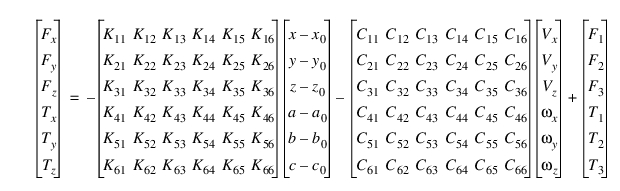
The following constitutive equations define how Adams Solver (C++) uses the data for a linear field to apply a force and a torque to the I marker depending on the displacement and velocity of the I marker relative to the J marker.
For a nonlinear field, the following constitutive equations are defined in the FIESUB subroutine:
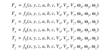
Adams Solver (C++) applies the defined forces and torques at the I marker. In the linear and nonlinear equations:
■Fx, Fy, and Fz are the three translational force measure numbers.
■Tx, Ty, and Tz are the three rotational force measure numbers associated with unit vectors directed along the x-, y-, and z-axis of the J marker.
■K is the stiffness matrix.
■x0, y0, z0, a0, b0, and c0 are the free lengths.
■x, y, z, a, b, and c are the translational and the rotational displacements of the I marker with respect to the J marker expressed in the coordinate system of the J marker.
■Vx,Vy,Vz, ,
, , and
, and  are the time derivatives of the deformation, respectively; C is the damping matrix.
,, and are the time derivatives of the deformation, respectively; C is the damping matrix. ■F1, F2, F3, T1, T2, and T3 are the translational and the rotational pre-tensions.
All variables and time derivatives are computed in the J marker coordinate system.
Adams Solver (C++) applies an equilibrating force and torque at the J marker, as defined by the following equations.
Fj = -Fi
Tj = -Ti - L x Fi
L is the instantaneous vector from the J marker to the I marker. While the force at the J marker is equal and opposite to the force at the I marker, the torque is usually not equal and opposite, because of vector L.
Nonlinear theory
When using the FORMULATION=NONLINEAR option, the force equations are modified by adding a geometric stiffness term
F = (K + Kg)U.
Kg is described in reference [1] and it is used to include nonlinear geometric effects. Matrix Kg has the following structure:
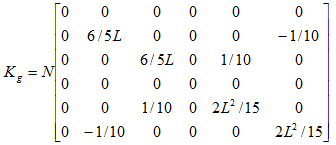
N is the current axial load and L is the largest of the current instantaneous length and the length tolerance. Option NONLINEAR shall be used when the FIELD models a beam like element and you need to include geometrically nonlinear effects.
Tip: | ■A FIELD statement can define any six-component, action-reaction force. However, when defining massless beams, you may want to use a BEAM statement. It requires only six input values to compute the thirty-six values for the Kmatrix (see BEAM). ■Finite element analysis programs can give the values for CMATRIX and KMATRIX. |
Caution: | ■For the constitutive equations to be accurate, at least two of the rotations (a, b, c) must be small. That is, two of the three values must remain smaller than 10 degrees. In addition, if a becomes greater than 90 degrees, b becomes erratic. If b becomes greater than 90 degrees, a becomes erratic. Only c can become greater than 90 degrees without causing problems. For these reasons, it is best to define your field such that angles a and b (not a and c and not b and c) remain small. ■The three rotational displacements (a, b, and c) that define the field are not Euler angles. They are the projected angles of the I marker with respect to the J marker. Adams Solver (C++) measures them about the x-, y-, and z-axis of the J marker. ■Adams Solver (C++) applies the component translational and rotational forces for a field to the I marker and imposes reaction forces on the J marker. ■The K and C matrices must be positive semidefinite. In other words: xtK x > 0 for all non-zero displacements x, and ytC y > 0 for all non-zero velocities y. If this is not true, the stiffness matrix of the field may be removing energy from the system. Similarly, the damping matrix may be adding energy to the system. Both of these situations are uncommon. Adams Solver (C++) does not warn you if the C matrix, K matrix, or both are not positive semidefinite. While Adams Solver (C++) does not require that these matrices be symmetric, it is most realistic. By definition, a FIELD element is asymmetric. Holding the J marker fixed and deflecting the I marker produces different results from holding the I marker fixed and deflecting the J marker by the same amount. This asymmetry occurs because the coordinate system frame that the deflection of the field is measured in, moves with the J marker. This asymmetry is similar to other force elements like BUSHING and BEAM. Here are some best practices that will help avoid the effects of asymmetry for the FIELD element. 1. Be sure to follow the above recommendation on rotations. Projection angles a (about X) and b (about Y) should be small (less than 10 degrees) in order for the rotational constitutive equations to be somewhat accurate. 2. The closer I and J marker are in location the better so that the moment arm and hence reaction torque is small. Note that even if markers I and J are coincident the FIELD may start to behave asymmetrically due to deflection. Consider splitting the FIELD into two elements that reference the same two markers, one with markers I and J defined in reverse from the other. For this case, you will also need to divide by two the properties such as stiffness of the original FIELD since the two fields will be in parallel. This would provide symmetry to the forces since the reaction torque would be applied equally to both sides. |
Examples
Consider a cantilever, semimonocoque wing structure like the figure below.
Cantilever, Semimonocoque Wing Structure
In order to model the elastic freedoms at location I shown in the figure, the system stiffness matrix must first be determined for the retained degrees of freedom. A finite element super element analysis is one method for determining the matrix. Assume that all other degrees of freedom are either constrained or superfluous for this analysis. The system stiffness matrix is:
X | Z |  y y | |
X | 0.198E+04 | 0.126E-01 | -0.147E+04 |
Z | 0.126E-01 | 0.208E+03 | -0.933E-02 |
 y y | -0.147E+04 | -0.933E-02 | 0.763E+07 |
Inserting these entries into a full six-by-six FIELD array yields:
X | Y | Z |  x x |  y y |  z z | |
X | 0.198E+04 | 0 | 0.126E-01 | 0 | -0.147E+04 | 0 |
Y | 0 | 0 | 0 | 0 | 0 | 0 |
Z | 0.126E-01 | 0 | 0.208E+03 | 0 | -0.933E-02 | 0 |
 x x | 0 | 0 | 0 | 0 | 0 | 0 |
 y y | -0.147E+04 | 0 | -0.933E-02 | 0 | 0.763E+07 | 0 |
 z z | 0 | 0 | 0 | 0 | 0 | 0 |
The FIELD statement describing these elastic forces applied to Marker 100 due to displacement of Marker 100 relative to Marker 57 is:
FIELD/1, I=100, J=57, KMATRIX=0.198E+04
, 0, 0.126E-01, 0, -0.147E+04, 0,
, 0, 0, 0, 0, 0, 0,
, 0.126E-01, 0, 0.208E+03, 0, -0.933E-02, 0,
, 0, 0, 0, 0, 0, 0,
,-0.147E+04, 0, -0.933E-02, 0, 0.763E+07, 0,
, 0, 0, 0, 0, 0, 0
, LENGTH=0, 150, 0, 0, 0, 0
, 0, 0.126E-01, 0, -0.147E+04, 0,
, 0, 0, 0, 0, 0, 0,
, 0.126E-01, 0, 0.208E+03, 0, -0.933E-02, 0,
, 0, 0, 0, 0, 0, 0,
,-0.147E+04, 0, -0.933E-02, 0, 0.763E+07, 0,
, 0, 0, 0, 0, 0, 0
, LENGTH=0, 150, 0, 0, 0, 0
These entries must be made column by column. The distance between the I and J markers is zero except in the y direction (where it is 150).
See other Forces available.
References
1. Theory of Matrix Structural Analysis. J.S. Przemieniecki. Courier Dover Publications, 1985