FRICTION
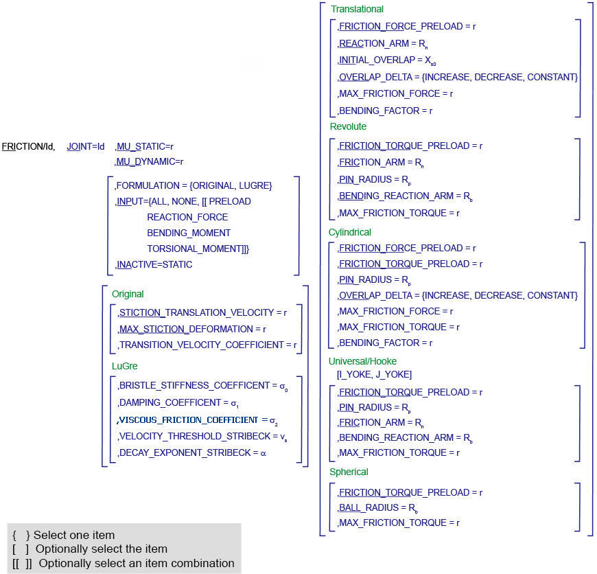
The FRICTION statement defines parameters for frictional forces on translational, revolute, cylindrical, hooke, universal, and spherical joints.
Note: | Frictional forces and torques are computed by Adams Solver (C++) using a friction model that supports dynamic friction and stiction. Both the stick-slip (original) and the LuGre formulations are supported. |
Format
Arguments
BALL_RADIUS=Rb | Defines the radius of the ball in a spherical joint for use in friction-force and torque calculations. Default: 1.0 Range: BALL_RADIUS > 0 |
BENDING_REACTION_ARM=Rb | Defines the effective moment arm use to compute the contribution of the bending moment on the net friction torque in revolute, hooke, and universal joints. Default: 1.0 Range: BENDING_REACTION_ARM > 0 |
STICTION_TRANSITION_VELOCITY=r | Defines the absolute velocity threshold for the transition from dynamic friction to static friction. If the absolute relative velocity of the joint marker is below STICTION_TRANSITION_VELOCITY, then static friction or stiction acts to make the joint stick. Default: 0.1 length units/unit time on the surface of contact in the joint. Range: STICTION_TRANSITION_VELOCITY > 0 |
EFFECT={ALL[[STICTION, SLIDING]]} | Defines the frictional effects included in the friction model. Stiction is static-friction effect, while sliding is dynamic-friction effect. Excluding stiction in simulations that don’t require it can greatly improve simulation speed. Default: All |
FRICTION_FORCE_PRELOAD=r | Defines the joint’s preload frictional force, which is usually caused by mechanical interference in the assembly of the joint. Default: 0.0 Range: FRICTION_FORCE_PRELOAD > 0 |
FRICTION_ARM=Rn | Defines the effective moment arm used to compute the axial component of the friction torque in revolute, hooke, and universal joints. Default: 1.0 Range: FRICTION_ARM > 0 |
INACTIVE=STATIC | Specifies that frictional forces not be calculated for a static or quasi-static solution. Default: none Range: Static |
INITIAL_OVERLAP=Xs0 | Defines the initial overlap of the sliding parts in either a translational or cylindrical joint. The joint's bending moment is divided by overlap to compute the bending moment's contribution to frictional forces. Default: 1000.0 Range: INITIAL_OVERLAP > 0 |
INPUTS=( {ALL, NONE [[PRELOAD: REACTION_FORCE: BENDING_MOMENT: TORSIONAL_MOMENT]]} ) | Defines the input forces to the friction model. By default, all user-defined preloads and joint-reaction force and moments are included. You can customize the friction-force model by limiting the input forces you list in the statement. Default: ALL Joint Type: (Available inputs) Translational (PRELOAD, REACTION_FORCE, BENDING_MOMENT, TORSIONAL_MOMENT) Cylindrical, Revolute, Universal, Hooke (PRELOAD, REACTION_FORCE, BENDING_MOMENT) Spherical (PRELOAD, REACTION_FORCE) |
JOINT=id | Identifies the joint to which frictional forces apply. |
MAX_STICTION_DEFORMATION=r | Defines the maximum creep that can occur in a joint during the stiction regime. The creep allows Adams Solver (C++) to impose the Coulomb conditions for stiction or static friction, for example: Friction force magnitude < µstatic * normal force Therefore, even at zero velocity, a finite stiction force is applied if your system dynamics requires it. Default: 0.01 length units Range: MAX_STICTION_DEFORMATION > 0 |
MU_DYNAMIC=r | Defines the coefficient of dynamic friction. During the sliding regime, the magnitude of the frictional force is the product of MU_DYN and the magnitude of the normal force in the joint, for example: Friction force magnitude, F = µN where µ = MU_DYNAMIC and N = normal force The dynamic frictional force acts in the opposite direction of the velocity of the joint. Default: none Range: MU_DYNAMIC > 0 |
MU_STATIC=r | Defines the coefficient of static friction in the joint. The magnitude of the frictional force is the product of a function of MU_STAT, MU_DYNAMIC, and the creep, times the magnitude of the normal force in the joint, for example: Friction Force Magnitude, F = µN where µ = f (MU_STATIC, MU_DYNAMIC, creep) and N = normal force The static frictional force acts to oppose the net force or torque along the degrees of freedom of the joint. Default: none Range: MU_STATIC > 0 |
OVERLAP_DELTA={INCREASE, DECREASE, CONSTANT} | To define friction in a sliding joint (either a translational or a cylindrical joint), Adams Solver (C++) computes the overlap of the joint. As the joint slides, the overlap can increase, decrease, or remain constant. OVERLAP_DELTA is used to define any change in overlap. ■INCREASE indicates that overlap increases as the I marker translates in the positive direction along the J marker; the slider moves to be within the joint. ■DECREASE indicates that the overlap decreases with positive translation of the joint; the slider moves outside of the joint. ■CONSTANT indicates that the amount of overlap does not change as the joint slides; all of the slider remains within the joint. Default: CONSTANT |
MAX_FRICTION_FORCE = r | Defines the maximum of the friction force for use in translational or cylindrical joint. Default: 1.0E+40 Range: MAX_FRICTION_FORCE > 0 Note: When there is a preload friction force applied to the joint, the MAX_FRICTION_FORCE is set to be: FRICTION_FORCE_PRELOAD+MAX_FRICTION_FORCE. |
BENDING_FACTOR = r | Defines the coefficient that multiplies the term Tm/Xs when the BENDING_MOMENT input is used for the friction force computation. This coefficient was hardcoded to 1.0 in releases previous to 2016. Default: 1.0 Range: BENDING_FACTOR>0. |
MAX_FRICTION_TORQUE = r | Defines the maximum of the friction torque for use in revolute, universal, hooke, spherical, or cylindrical joint. Default: 1.0E+40 Range: MAX_FRICTION_TORQUE > 0 Note: When there is a preload friction torque applied to the joint, the MAX_FRICTION_TORQUE is set to be: FRICTION_TORQUE_PRELOAD+MAX_FRICTION_TORQUE. |
TRANSITION_VELOCITY_COEFFICIENT = r | Defines the absolute velocity threshold for the transition from static friction to dynamic friction. If the absolute relative velocity of the joint marker is at or above TRANSITION_VELOCITY_COEFFICIENT * STICTION_TRANSITION_VELOCITY, then the dynamic friction coefficient is applied. Between STICTION_TRANSITION_VELOCITY and TRANSITION_VELOCITY_COEFFICIENT * STICTION_TRANSITION_VELOCITY the coefficient of friction is transitioning from the static coefficient of friction to the dynamic coefficient of friction. Default: 1.5 Range: TRANSITION_VELOCITY_COEFFICIENT > 1 |
PIN_RADIUS=Rp | Defines the radius of the pin for a revolute, cylindrical, hooke, or universal joint. Default: 1.0 Range: PIN_RADIUS > 0 |
REACTION_ARM=Rn | Defines the effective moment arm of the joint-reaction torque about the translational joint’s axial axis (the z-direction of the joint’s J marker). This value is used to compute the contribution of the torsional moment to the net frictional force. Default: 1.0 Range: REACTION_ARM > 0 |
FRICTION_TORQUE_PRELOAD=r | Defines the preload friction torque in the joint, which is usually caused by mechanical interference in the assembly of the joint. Default: 0.0 Range: FRICTION_TORQUE_PRELOAD > 0 |
I_YOKE J_YOKE | I_YOKE and J_YOKE define the rotational constraint on which the FRICTION statement acts. I_YOKE identifies the yoke to the I marker’s rotational constraint. Likewise, J_YOKE identifies the yoke to the J marker’s rotational constraint. These keywords are used with only hooke and universal joints. |
FORMULATION = {original, lugre} | Defines the formulation that Adams uses to calculate the frictional force. Default: original |
BRISTLE_STIFFNESS_COEFFICIENT = r | Defines the stiffness coefficient of the bristle and is the coefficient  in the LuGre formulation. in the LuGre formulation.Default: 1e4 Range: BRISTLE_STIFFNESS_COEFFICIENT > 0 |
DAMPING_COEFFICIENT = r | Defines the damping coefficient in the rate of microscopic deflection and is the coefficient  in the LuGre formulation in the LuGre formulationDefault: 1e2 Range: DAMPING_COEFFICIENT >= 0 |
VISCOUS_FRICTION_COEFFICIENT = r | Defines the damping coefficient of the viscous component of the friction force and is the coefficient  in the LuGre formulation in the LuGre formulationDefault: 0 Range: VISCOUS_FRICTION_COEFFICIENT >= 0 |
VELOCITY_THRESHOLD_STRIBECK = r | Defines the threshold of the Stribeck velocity and is the vs component in the LuGre formulation Default: 1e-3 Range: VELOCITY_THRESHOLD_STRIBECK > 0 |
DECAY_EXPONENT_STRIBECK = r | Defines the exponent of the Stribeck friction decay and is the  component in the LuGre formulation component in the LuGre formulationDefault: 2 Range: DECAY_EXPONENT_STRIBECK > 0 |
Extended Definition
Original Formulation
0.1 Application of Friction in Joints
This section provides graphical descriptions and block diagrams of the joints and friction regimes available in the FRICTION statement.
To learn about block diagrams and friction regimes, see:
To find information on a particular joint, see:
0.1.1 Conventions in Block Diagrams
The following tables identify conventions used in the block diagrams:
■Table 1 identifies symbols in the diagrams.
■Table 2 describes the relationship between the INPUTS argument in the FRICTION statement and the switches used in the block diagrams.
Table 1 Legend for Block Diagrams
Symbol: | Description: |
_________ | Scalar quantity |
 | Vector quantity |
 | Summing junction: c=a+b |
 | Multiplication junction: c=axb |
MAG | Magnitude of a vector quantity |
ABS | Absolute value of a scalar quantity |
FRD | Friction regime determination |
Table 2 Relationship Between the INPUTS Argument and Switches Used in the Block Diagrams
Switch: | INPUTS=: | Symbol: | Acceptable Values: |
SW1 | PRELOAD | Fprfrc or Tprfc | ON/OFF |
SW2 | REACTION FORCE | F or T | ON/OFF |
SW3 | BENDING MOMENT | Tr | ON/OFF |
SW4 | TORSIONAL MOMENT | Tn | ON/OFF |
ALL/NONE sets all applicable switches ON/OFF, respectively |
0.1.2 Friction Regime Determination (FRD)
Three friction regimes are permissible in Adams:
Dynamic friction | A joint is in dynamic friction if its joint velocity magnitude exceeds the value of the transition velocity coefficient multiplied by the friction transition velocity. The dynamic coefficient of friction (md) is used in the computation of frictional forces. |
Transition between dynamic and static friction | If the joint velocity magnitude is between the value of the transition velocity coefficient multiplied by the stiction transition velocity and friction transition velocity, the joint is considered to be transitioning between static and dynamic friction. A STEP function transitions the coefficient of friction between the dynamic (md) and static (ms) coefficients of friction. |
Static friction | A joint is in static friction when the joint velocity magnitude falls below the stiction transition velocity. The effective coefficient of friction is computed using the joint creep, joint velocity, and static coefficient of friction (ms). |
The joint velocity determines the instantaneous friction regime for a joint. The figure below shows the block diagram of the friction regimes available in Adams Solver (C++).
LuGre Formulation
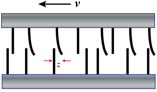
Figure 15
Although the LuGre friction model has limitations [3, 4], it is still used in several fields due to its simplicity and faster simulation times. LuGre friction model is a type of state variable friction models, where extra state variables (internal states) are introduced to determine the level of friction. For LuGre friction model, the microscopic average bristle deflection z of the contact surface is adopted as the state variable, see Figure 15. Therefore, the friction can be considered as the forces produced by the bending bristles. In 1D translational joint cases, the friction is given by
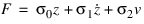 | (1) |
where  is the bristle stiffness,
  is the microscopic damping, and
  is the viscous friction coefficient. Notice that
  since z represents the average deflection rate of the bristle while v is the velocity of the contact body. To determine the value of z, an additional differential equation is used in the formulation
is the bristle stiffness, is the microscopic damping, and is the viscous friction coefficient. Notice that since z represents the average deflection rate of the bristle while v is the velocity of the contact body. To determine the value of z, an additional differential equation is used in the formulation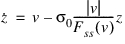 | (2) |
where
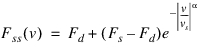 | (3) |
N is the normal contact force, Fs and Fd are the maximum static friction and dynamic friction,  and
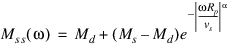
and  are dynamic and static frictional coefficients, respectively. Fss(v) represents the steady-state LuGre friction for a specific v, where
  and z=const.
and are dynamic and static frictional coefficients, respectively. Fss(v) represents the steady-state LuGre friction for a specific v, where and z=const. For 1D revolute joint cases, the frictional forces between the pin and hole result in the frictional torque, which is given by

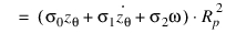 | (4) |
where Rp is the pin radius,  is the angular displacement,
  . Based on Eq. (2), the additional differential equation is obtained as
is the angular displacement, . Based on Eq. (2), the additional differential equation is obtained as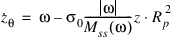 | (5) |
where
 | (6) |
 represents the steady-state LuGre frictional torque for a specific
  , where
  and
and  =const.
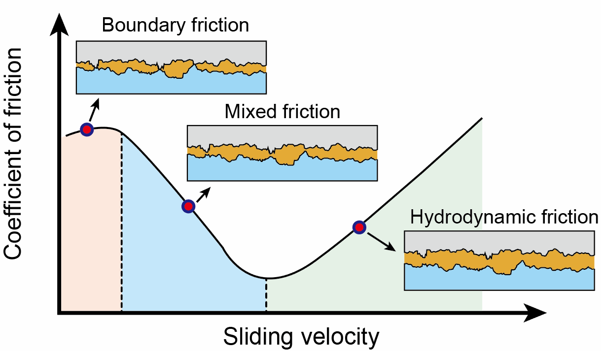
Figure 16
In the cases where only dry friction is considered,  , which determines whether viscous friction is considered in the model, should be zero. Stribeck velocity vs is always small and is used to determine the range of Stribeck effect. Stribeck effect decay exponent
  is used to determine the decay speed (the shape of Stribeck effect curve), as shown in Figure 16 Different
  values between 0.5 and 2 are recommended in the literature, and
  =2 is the default in Adams.
, which determines whether viscous friction is considered in the model, should be zero. Stribeck velocity vs is always small and is used to determine the range of Stribeck effect. Stribeck effect decay exponent is used to determine the decay speed (the shape of Stribeck effect curve), as shown in Figure 16 Different values between 0.5 and 2 are recommended in the literature, and =2 is the default in Adams.Examples
FRICTION/102, JOINT=102, I_YOKE
, FORMULATION = ORIGINAL
, Mu_Static=0.03, Mu_Dynamic=0.024
, Stiction_Transition_Velocity=0.1
, Max_Stiction_Deformation=0.15
, Pin_Radius=12.25
, Friction_Arm=8.2
, Effect=All
, Inputs=Reaction_Force
, FORMULATION = ORIGINAL
, Mu_Static=0.03, Mu_Dynamic=0.024
, Stiction_Transition_Velocity=0.1
, Max_Stiction_Deformation=0.15
, Pin_Radius=12.25
, Friction_Arm=8.2
, Effect=All
, Inputs=Reaction_Force
This statement creates stick-slip frictional forces about the rotational degree of freedom associated with the I marker’s part of either a hooke or universal joint. The following items apply:
■We assume that the joint has a 12.25 length-unit-radius pin and an effective-friction-moment arm that is at the end caps of 8.2 length units.
■The friction model includes dynamic- and stiction-friction effect. The static-friction coefficient is .03 and the dynamic-friction coefficient is .024.
■When computing the frictional force, Adams Solver (C++) identifies only the joint-reaction forces as force inputs.
■The transition from dynamic friction to stiction occurs when the relative angular velocity in the joint falls below 0.1 units of length/unit time. A maximum deflection of 0.15 length units is permitted when the joint is stiction.
FRICTION/103, JOINT=103
, FORMULATION = LUGRE
, MU_STATIC = 0.3, MU_DYNAMIC = 0.25
, BRISTLE_STIFFNESS_COEFFICIENT = 1e4
, DAMPING_COEFFICIENT = 1e3
, VISCOUS_FRICTION_COEFFICIENT = 0
, VELOCITY_THRESHOLD_STRIBECK = 1e-3
, DECAY_EXPONENT_STRIBECK = 2
, INPUTS = REACTION_FORCE
This statement creates LuGre frictional forces for the 1-DOF translational joint. The following items apply:
■The friction force is calculated based on the LuGre friction formulation. The static-friction coefficient is 0.3 and the dynamic-friction coefficient is 0.25.
■The bristle stiffness and damping are 1e4 (units of force/length) and 1e2 (units of force*time/length).
■The viscous friction is ignored
■The Stribeck velocity threshold and decay exponent are 1e-3 (units of length/time) and 2 (units of 1).
■When computing the frictional force, Adams Solver (C++) only uses the joint-reaction forces as force inputs.
See other Forces available.
References
1. Marques F., Flores P., Claro J.C.P., Lankarani H.M. A survey and comparison of several friction force models for dynamic analysis of multibody mechanical systems. Nonlinear Dynam., 86 (3) (2016), pp. 1407-1443, 10.1007/s11071-016-2999-3.
2. Berger E. J., Friction modeling for dynamic system simulation. Appl. Mech. Rev. Nov 2002, 55(6):535:577.
3. Karl Johan Åström, Carlos Canudas De Wit. Revisiting the LuGre friction model. IEEE. Control Systems Magazine, Institute of Electrical and Electronics Engineers (IEEE), 2008, 28(6), pp.101-114. <10.1109/MCS.2008.929425>. <hal-00394988>
4. Schuderer M., Rill G., Schaeffer T., Schultz C. Friction Modeling from a Practical Point of View. ECOMAS Thematic Conference on Multibody Dynamics. July 24-28, 2023, Lisbon, Portugal.
5. Do N. B., Ferri A. A., Bauchau O. A., Efficient Simulation of a Dynamic System with LuGre Friction. J. Comput. Nonlinear Dynam. Oct 2007, 2(4): 281-289.