PART
The PART statement defines the inertial properties of a rigid body and its initial position, orientation, and velocity. Parts can have any shape or size and are the only model elements that can have mass, although they can be massless under certain circumstances. Adams Solver (C++) assumes that all parts are rigid bodies. The PART statement is also used to specify which part is used as the fixed inertial (or ground) global coordinate system. Each movable part (that is, other than ground) can add up to six degrees of freedom (DOF) to a system.
Format
Arguments
CM=id | Specifies the identifier of the marker that defines the location of the part center of mass and, in the absence of the inertia marker, the orientation of the inertia axes for the IP values. |
EXACT=c1:...:c6 | Specifies as many as six part coordinates that Adams Solver (C++) should not change as it iteratively solves for initial conditions that satisfy all constraints. The six coordinates are : 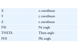 These coordinates can be entered in any order following EXACT. Adams Solver (C++) does not change these unless the values specified are inconsistent with initial conditions for a joint or defined motion. |
GROUND | Indicates the part being defined as the Newtonian reference frame. It is, by definition, at absolute rest. Because there can be only one ground part in the system, a dataset must never have more than one PART statement with the GROUND argument. |
IM=id | Specifies the identifier of the marker about which you specify the moments of inertia for the part. This marker can be any marker in the part. The IM marker defaults to the CM marker. |
IP=xx,yy,zz[,xy,xz,yz] | Specifies the mass-inertia tensor as computed about the origin of the IM marker, expressed in the coordinate system of the IM marker. You can compute the individual terms of the IP argument as: 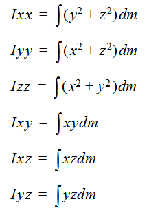 In the above formulae, x, y, and z are the components of the displacement of the center of an infinitesimal volume of mass dm, measured from the origin of the inertia marker in the coordinate system of the inertia marker. The integral is performed over the entire volume of the body. If the inertia marker is not specified, it defaults to the CM marker. In that case, these quantities are computed about the origin of the CM marker in the coordinate system of the CM marker. Note: Adams Solver (C++) defines Ixy, Ixz and Iyz as positive integrals, as shown. Some references define these terms as the negative of these integrals. Be sure to compute these values as shown above. See section Inertia input data for more information. |
MASS=r | Specifies the part mass. |
PLANAR | Indicates that the part only has three degrees of freedom. These are global x and y translations and a rotation about the global z axis. The body can have a constant z offset as given by the QG argument. It is best to think of the planar part as a regular 3D part with a built-in planar joint connected to ground. |
QG=x,y,z | Defines the Cartesian initial coordinates of the origin of the body coordinate system (BCS) with respect to the global coordinate system (GCS). |
REULER=a,b,c | Defines the 3-1-3 Euler angles that Adams Solver (C++) uses to establish the initial orientation of the BCS with respect to the coordinate system. The a, b, and c rotations are in radians and are, respectively, about the z-axis of ground, the new x-axis, and the new z-axis of the BCS. To input Euler angles in degrees, add a D after each value. |
VM=id | Specifies the identifier of the marker that specifies the direction of translational velocity initial conditions (VX, VY, and VZ). VM defaults to global orientation. |
VX=x, VY=y, VZ=z | Specifies the initial translational velocities of the CM marker with respect to the ground coordinate system (GCS) along the x-axis (VX), the y-axis (VY), and the z-axis (VZ) of the VM coordinate system. |
WM=id | Specifies the identifier of the marker that specifies the axes about which angular velocity initial conditions (WX, WY, and WZ) are defined. WM defaults to the CM location and orientation. The origin of the WM marker lies on the axis of rotation. This is most useful for rotating systems. A typical application is a spinning flexible satellite model in space. In this case, you add a marker to your system at the combined CG location of the system and orient the marker such that one of its axes is along the spin axis of the satellite. |
WX=a, WY=b, WZ=c | Specifies the initial rotational velocities, in radians per second, of the part about the x-axis (WX), the y-axis (WY), and the z-axis (WZ) of the WM coordinate system. Note: WM can also contribute to the initial translation velocities, V as 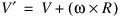 |
XG=x,y,z | Defines the coordinates, measured in the GCS, of any point in the positive x-z plane of the part BCS, but not on the z-axis of the part BCS. |
XY | Specifies that a planar part will move in the global xy plane. The argument can only appear with the PLANAR argument and is the default. |
YZ | Specifies that a planar part will move in the global yz plane. The argument can only appear with the PLANAR argument. If it is not provided, the planar part will move in the global xy plane. |
ZG=x,y,z | Defines the coordinates measured in the GCS of any point on the positive z-axis of the BCS. |
ZX | Specifies that a planar part will move in the global zx plane. The argument can only appear with the PLANAR argument. If it is not provided, the planar part will move in the global xy plane. |
Tip: | ■If the part has no CM marker, as may be the case for some massless parts, Adams Solver (C++) uses the part BCS to represent the position and orientation of the part internally. For more information on BCS, see Coordinate Systems and Local Versus Global Geometric Data. ■Using a CM on a massless part can improve model robustness by removing large offsets between the BCS and markers on the massless part, without repositioning all the markers on the massless part. Do not be confused by the contradiction of specifying a center-of-mass on a massless part. In this case, the CM marker is simply suggesting an advantageous choice of internal coordinate systems. ■If the part has mass, Adams Solver (C++) uses the position of the CM marker to represent the translational position of the part internally and uses the principal axes of the inertia tensor about the CM marker to represent the orientation of the part internally. This internal coordinate system is commonly referred to as the part principal coordinate system. ■Because of a basic property of Euler angles, a singularity occurs when the principal z-axis of the CM becomes parallel to the ground z-axis. Whenever the principal z-axis of the part nearly parallels the ground z-axis, Adams Solver (C++) rotates the part principal axes 90 degrees about the z-axis and then 90 degrees about the new x-axis to avoid the singularity. Adams Solver (C++), however, does not change the marker locations and orientations with respect to the BCS nor does it alter the BCS location or orientation with respect to ground. (The principal axes of the inertia tensor of the CM are referred to as the part principal axes.) ■The BCS for each part can have any position and orientation. In fact, the location of the BCS does not have to be within the physical confines of the part. It may be at some convenient point outside the actual part boundaries. ■To superimpose the BCS of a part on the GCS, define QG=0,0,0 and REULER=0,0,0 or let QG and REULER default. The position and orientation data for the markers on the part is now with respect to the GCS. ■As stated earlier, the planar can be viewed as a normal 3D part with a built-in planar joint. This is a combination of elements often found in certain models that contain 2D subsystems. Unlike a part and a planar joint pair that combine to add 18 equations to an index-3 dynamic analysis in Adams Solver, the planar part only adds 6 equations. ■This is not an attempt to create a 2D version of Adams. Because the planar part can be contained in a full 3D Adams model and coexist with, and be connected to, 3D part elements, performance will not compare with a 2D dynamics analysis software. |
Caution: | ■Each part defined with the PART statement, with the exception of ground, must have at least one marker associated with it (see MARKER). ■For the argument IP, if you specify one of the moments of inertia (xx, yy, or zz), you must also specify the other two. Similarly, if you specify one of the products of inertia (xy, xz, or yz), you much also specify the other two. ■Make sure the units for mass moments of inertia and for mass products of inertia are consistent with the units for the rest of the system. ■Parts that are not fully constrained (that is, they can move dynamically because of the effect of forces) must have nonzero masses and/or inertias. You may assign a default zero mass to a part whose six degrees of motion are fully constrained with respect to parts that do have mass. ■EXACT, VX, VY, VZ, WX, WY, and WZ arguments ensure that the corresponding displacements or velocities are maintained to an accuracy of six digits. Accuracy beyond six digits is not guaranteed. ■Use the EXACT, VX, VY, VZ, WX, WY, and WZ arguments with caution. Do not specify more initial displacements to be exact than the system has degrees of freedom. After you are sure the system has zero or more degrees of freedom, look at the model and see if the remaining set of part motions will permit Adams Solver (C++) to adjust the system to satisfy all the initial conditions. Remember that IC, ICTRAN, and ICROT arguments on the JOINT statement remove degrees of freedom from a system during initial conditions analysis. Similarly, do not specify more initial velocities than the system has degrees of freedom. ■A part without mass cannot have moments of inertia, initial conditions on displacement or velocity, or an IM marker. ■If you specify the mass for a part, you must also specify the CM marker for the part. ■A planar part is implicitly constrained to move in a plane at a fixed global value of Z. Any force applied to the planar part in the global Z direction will be discarded. The same applies to torques about the global X and Y axes. It is not possible to measure the reaction forces required to constrain the planar part to stay in plane. If such forces are desired, the equivalent part and planar joint combination must be substituted. |
Examples
PART/01, GROUND
The PART statement above indicates that Part 1 is the ground part.
PART/02, MASS=2, CM=0201, IP=5,6,10
The PART statement above specifies the mass (2 units), the center-of-mass marker identifier (0201), and the principal moments of inertia for Part 2:
■Ixx = 5 units
■Iyy = 6 units
■Izz = 10 units
The principal moments of inertia are about the x-axis (5), the y-axis (6), and the z-axis (10) of the center-of-mass marker. Because this statement includes no arguments that define the orientation or position of Part 2, Adams Solver (C++) superimposes Part 2 on the ground coordinate system (GCS). This statement identifies no IM marker, so Adams Solver (C++) assumes that the inertias are defined with respect to the part CM marker.
PART/04, MASS=.5, CM=0407, QG=10,0,0
The statement above specifies:
■Mass (.5 units)
■Center-of-mass marker identifier (0407)
■Initial position of the BCS (10,0,0) with respect to the ground coordinate system (GCS).
This statement does not define the principal moments of inertia, so the inertia of the part is zero about each of the CM marker axes. In addition, this statement has no arguments to indicate the orientation of Part 4, so Adams Solver (C++) aligns the axes of the BCS of Part 4 with the axes of the GCS.
Inertia input data
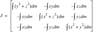
The inertia matrix to be assembled into the equations of motion is the following:
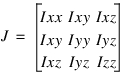
A lot of confusion arises by the way different computer codes ask for above entries of the J matrix. There are two conventions. On one hand, some computer programs define the J matrix as follows (this is not the way Adams Solver defines the J matrix):
 .
.Clearly, the user is requested to compute the above values of Ixx, Iyy, Izz, Ixy, Ixz and Iyz. If that is the case, the user needs to compute say
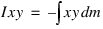
and enter that value.
On the other hand, some other computer programs (for example, Adams Solver) define the J matrix as follows:
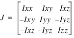 .
.In that case the user is requested to compute

and enter that value. In other words, the negative sign is applied by the computer code. Adams Solver follows the latter convention. Both Adams Solver and Nastran follow the same convention.
See other Inertia and material data statement available.