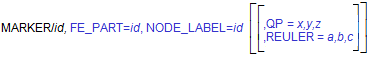
MARKER
The MARKER statement defines three mutually perpendicular coordinate axes emanating from a common origin. A marker can exist on a PART, POINT_MASS, FLEX_BODY, FE_PART, CURVE, SURFACE, or GROUND.
Format
Arguments
CURVE=id | Specifies the identifier of the CURVE along which the marker will move. Range: Curve IDs |
FLOATING | Defines the marker as ones that moves relative to the PART with which it is associated. A floating marker must be used with VTORQUE, VFORCE, GFORCE, CVCV, and PTCV, and cannot exist without being referenced by one of these statements. |
FLEX_BODY=id | Specifies the identifier of the flexible body to which the marker belongs. A FLEX_BODY argument is not required in the MARKER statement if the MARKER statement follows the associated FLEX_BODY statement with no intervening FLEX_BODY or PART statements. Default: ID of preceding PART or FLEX_BODY Range: Flexible body IDs |
NODE_ID=n1, [n2,...,nn] | Specifies that a marker (associated with a FLEX_BODY statement) is to be attached, not necessarily positioned, to the points on a structure defined by the finite element nodes n1, n2,...,nn. If the NODE_ID argument is not specified for a Marker on a FLEX_BODY, then the Marker will be attached to the flexible body's center of mass by means of a rigid link. Note that the NODE_ID argument is ignored by Solver when the Marker belongs to a PART. Default: None Range: IDs of nodes on the FLEX_BODY |
FE_PART=id | Specifies the identifier of the FE_PART to which the marker belongs. |
NODE_LABEL = id | Specifies a node to which a marker (associated with an FE_PART statement) is attached to. The marker may not be necessarily coincident with the node. Adams Solver C++ will compute the initial offset (position and/or orientation) to the node and it will keep the offset in subsequent computations. |
PART=id | Specifies the identifier of the part to which the marker belongs. A PART argument is not required in the MARKER statement if the MARKER statement follows the associated PART statement with no intervening FLEX_BODY or PART statements. Default: ID of preceeding PART or FLEX_BODY Range: Part IDs |
POINT_MASS=id | Specifies the identifier of the point mass to which the marker belongs. A POINT_MASS argument is not required in the MARKER statement if the MARKER statement follows the associated POINT_MASS statement with no intervening FLEX_BODY, PART, or POINT_MASS statement. Default: ID of preceding FLEX_BODY, PART or POINT_MASS Range: Point mass IDs |
QP=x,y,z | Defines the x-, y-, and z-coordinates of the origin of the MARKER with respect to the element on which it lies. If the marker is associated with a FE_PART, FLEX_BODY or PART, the coordinates are specified in the body coordinate system (BCS). For a marker on a FE_PART or FLEX_BODY, the position specified by QP does not have to be coincident with a node. For markers associated with CURVES and SURFACES, the coordinates are specified in the RM coordinate system and are susceptible to change as the Adams Solver (C++) iteratively solves for initial conditions that satisfy all constraints while maintaining the marker on the curve. Range: Real numbers for x, y, and z |
RM=id | Defines a reference marker for CURVE and SURFACE markers on the same part with respect to which Adams Solver (C++) interprets QP, XP, ZP, and REULER. |
REULER=a,b,c | Specifies the Euler angle 3-1-3 sequence rotation defining the spatial orientation of the marker axes relative to the element on which it lies. If the marker is associated with a FE_PART, FLEX_BODY or PART, the orientation is relative to the body coordinate system (BCS). For markers associated with CURVES and SURFACES, the orientation is relative to the natural coordinate system of the CURVE or SURFACE. For every point on a CURVE or SURFACE, Adams Solver (C++) computes a natural coordinate system defined by tangent, normal, and binormal orthonormal vectors. In general, as the solution progresses and the marker moves along the CURVE or SURFACE, the orientation of the natural coordinate system changes, but the orientation of the marker relative to the natural coordinate system remains fixed. The fixed orientation of the marker relative to the natural coordinate system is defined by the Euler angle 3-1-3 sequence a,b,c. The a, b, and c, values represent the set of body-fixed 3-1-3 Euler angles expressed in radians. These angles can be interpreted by following the steps below. To orient a marker: 1. Align the marker axes identical to the axes of the parent coordinate system to which the orientation will be relative. 2. Perform a right-handed rotation of the marker x- and y-axes by a radians about the positive z-axis of the marker. 3. Rotate the marker y- and z-axes by b radians about the current marker positive x-axis. 4. Perform a right-handed rotation of the x- and y-axes of the marker by c radian about the current z-axis of the marker. To enter the Euler angles in degrees instead of radians, add a D after each value. Range: Real numbers for a, b, and c |
SURFACE=id | Specifies the identifier of the SURFACE along which the marker will move. Range: Surface IDs |
USEXP | When using the x-point-z-point method of orientation, USEXP causes the marker to be oriented with the x-axis lying on XP, and ZP lying in the positive x-z plane. This is useful for orienting markers that are used in BEAM statements. Examples of using the ZP, XP and USEXP |
XP=x,y,z | By default, defines the coordinates of any point in the positive x-z plane of the marker, but not on the z-axis of the marker. A point on the positive x-axis may be the most convenient. When used with USEXP, XP defines the coordinates of any point on the positive x-axis of the marker. If the marker is associated with a FLEX_BODY or PART, the x-, y-, and z-coordinates are specified in the body coordinate system (BCS). For markers associated with CURVES and SURFACES, the x-, y-, and z-coordinates are specified in the natural coordinate system of the CURVE or SURFACE. For every point on a CURVE or SURFACE, Adams Solver (C++) computes a natural coordinate system defined by tangent, normal, and binormal orthonormal vectors. In general, as the solution progresses and the marker moves along the CURVE or SURFACE, the orientation of the natural coordinate system changes, but the orientation of the marker relative to the natural coordinate system remains fixed. The fixed orientation of the marker relative to the natural coordinate system is specified with XP and ZP arguments. Examples of using the ZP, XP and USEXP |
ZP=x,y,z | By default, defines the coordinates of any point on the positive z-axis of the marker. When used with USEXP, ZP defines the coordinates of any point in the positive x-z plane of the marker, but not on the x-axis of the marker. If the marker is associated with a FLEX_BODY or PART, the x-, y-, and z-coordinates are specified in the body coordinate system (BCS). For markers associated with CURVES and SURFACES, the x-,y- and z-coordinates are specified in the natural coordinate system of the CURVE or SURFACE. For every point on a CURVE or SURFACE, Adams Solver (C++) computes a natural coordinate system defined by tangent, normal, and binormal orthonormal vectors. In general, as the solution progresses and the marker moves along the CURVE or SURFACE, the orientation of the natural coordinate system changes, but the orientation of the marker relative to the natural coordinate system remains fixed. The fixed orientation of the marker relative to the natural coordinate system is specified with XP and ZP arguments. Examples of using the ZP, XP and USEXP |
VEL=r | For a marker associated with a CURVE, VEL=r defines the initial velocity of the marker origin along the curve. VEL is negative if the marker is initially moving toward the start of the curve, and it is positive if the marker is moving toward the end of the curve. |
VX=x, VY=y, VZ=z | For a marker on a CURVE or SURFACE, this argument specifies the initial translational velocity of the marker along the x-axis (VX), y-axis (VY), and z-axis (VZ) of the RM coordinate system. Adams Solver (C++) will project the initial velocity onto the CURVE or SURFACE. Therefore, any contribution of the specified initial velocity vector which is not along the CURVE or SURFACE will be discarded. |
V1=r1, V2=r2 | For a marker associated with a SURFACE, V1=r1, and V2=r2 define the initial velocity of the marker on the surface along the two-dimensional surface parameterization. |
Extended Definition
The MARKER statement defines a geometric point in space and a set of three mutually perpendicular coordinate axes emanating from that point. MARKERs are the basic building blocks for specifying applied forces, constraints, or simply points of interest in the model.
MARKERs are always associated with a specific element in the model (for example, PART, FLEX_BODY, CURVE, or SURFACE) and could be fixed on the element or move relative to it.
Markers on Parts
A marker on a PART can either be fixed or it may float relative to the PART. A MARKER statement identifies the location and orientation of a marker with respect to the body coordinate system (BCS).(For more information on BCS, see Coordinate Systems and Local Versus Global Geometric Data.) Requests for information pertaining to fixed and floating markers are easy to write (see REQUEST). However, only information on fixed markers can be used in function arguments that affect how the model behaves. You may reference the position of a floating marker in a REQUEST statement or a REQSUB evaluation subroutine, for example, but not in an SFORCE statement or a SFOSUB evaluation subroutine.
Markers on Flexible Bodies
Adams Solver (C++) distinguishes between positioning a marker on a flexible body and attaching a marker to a flexible body. Positioning the marker using arguments QP, REULER, ZP, and XP defines the initial position and orientation relative to the BCS of the flexible body. Attaching defines the interaction between the marker and the flexible body; namely, how forces acting on the marker will project onto the flexible body, and how the deformation of the flexible body will effect the kinematics of the marker.
A marker can be positioned anywhere on or off a flexible body and can be attached to zero or more nodes. In general, the position of the marker will be given by:
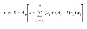
where:
x = Position vector of marker, resolved in the ground coordinate system (GCS)
X = Position vector of BCS, resolved in the GCS
Ao = Transformation matrix from BCS to GCS
n = Number of attachment nodes
s = Initial position of marker relative to BCS, resolved in the BCS
ui = Displacement vector of node i relative to BCS, resolved in the BCS
rc = Initial position of marker relative to the centroid of the attachment nodes, resolved in the BCS
Ai = Small rotation transformation from frame fixed to node i during deformation back to the BCS
ri = Initial position of node i relative to BCS, resolved in the BCS
I = 3 x 3 identity matrix
wi = Weighting parameter
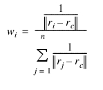
where wi satisfies,
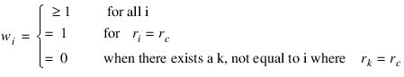
and the sum of wi equals one. Therefore, the position of a marker relative to BCS is a least square weighted average of the relative position of the attachment nodes in their deformed configuration. Furthermore, the kinematics of the marker are more strongly influenced by attachment nodes closer to the centroid of the attachment nodes.
Several marker attachment configurations can be obtained from the general form given above:
1. Marker positioned on a node, attached to the same node (n=1, w1=1, rc=0)
The position of the marker is then given by x = X + Ao [s + u1]
The position of the marker is then given by x = X + Ao [s + u1]
2. Marker positioned off node, attached to a single node (n=1, w1=1, rc=r1)
The position of the marker is then given by x = X + Ao (r1 + u1 + A1 (s - r1))
The position of the marker is then given by x = X + Ao (r1 + u1 + A1 (s - r1))
Note that the marker is not required to be on the flexible body. It is attached to the node by a rigid lever.
3. Marker positioned anywhere on or off the flexible body and attached to multiple nodes. This is the general case given above.
4. Marker positioned anywhere on or off the body and attached to no node (n=0). This is an exception case. Here, the position of the marker is given by standard rigid body marker kinematics: x = X + Aos
Important: | Warning messages for a node has zero mode shapes The warning messages is printed from C++ solver when a node has zero mode shapes is attached to some connectors in MD/MSC Adams 2011 and later. This message is inviting user's attention to find out a potential problem in the model because the flexibility of the node is infinite, the other words the node behave the same as the marker on rigid part, and it may not be user's intention. The example of the message for zero rotational mode shapes is shown below. 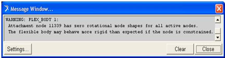 |
Floating Markers on Flexible Bodies
When applied to flexible bodies, a floating marker can be either associated with a node or not. Because a floating marker is often moving across the body to which it belongs, it typically does not make sense to associate a flexible body’s floating marker with any particular node. Be advised, that this means the reaction loads from the force object which the floating marker supports will be applied to the rigid body motion of the flexible body and not on a modal basis deforming the part locally at the nodes near the force application point.
Markers on Curves
The orientation (natural coordinate system) of curve markers is defined by the following convention:
■The x-axis of the curve marker will point along the curve tangent vector at the marker location.
■The y-axis of the curve marker will point along the curve normal vector at the marker location. The curve normal vector points from the marker location toward the center of curvature (if known).
■The z-axis of the curve marker will point along the curve BI-normal vector at the marker location. The curve BI-normal is defined as the cross product of the curve tangent and normal vectors.
Markers on Surfaces
The orientation (natural coordinate system) of surface markers is slightly more complex than curve markers because parameterized surfaces have two linearly independent tangent vectors.
■The x-axis of the surface marker will point along the surface u (alpha) tangent vector at the marker location.
■The z-axis of the surface marker will point along the surface v (beta) tangent vector at the marker location.
■The y-axis of the surface marker will point along the surface normal vector at the marker location.
Tip: | Select one of the following three methods to define the position and orientation of the marker. Note: In general, locate and orient a marker with respect to its parent BCS. If the marker is on the ground part or is on a part whose BCS is superimposed on the ground coordinate system (GCS) at time zero, the marker can be positioned and oriented with respect to the ground coordinate system (GCS). ■To select the Euler angles method, add QP and/or REULER. ■To select the x-point-z-point method using the ZP point to define a point on the z-axis, add QP, ZP, and/or XP. It is often unnecessary to define XP. ■To select the x-point-z-point method using the XP point to define a point on the z-axis, add QP, ZP, and/or ZP as well as USEXP. It is often unnecessary to define ZP |
Caution: | If a curve is a straight line, or it has inflection points, the center of curvature will not be uniquely defined at all of the curve points. In these situations, Adams Solver (C++) will still determine a normal, but it is just one possibility from an infinite set of normal vectors. It is also possible for the curve marker normal to jump discontinuously as it goes through an inflection point. In most situations, this will not cause a simulation to fail, but you should be aware that it can happen.The REULER arguments for curve and surface markers are relative to the curve/surface natural coordinate system. This is different from the usual REULER convention for rigid markers where the transformation is always relative to the part BCS. If the REULER arguments are at their default value (0,0,0) for a curve/surface marker, then the marker will coincide with the natural coordinate system. Rotational constraints applied to curve/surface markers must be done with care. For example, if you want to create a fixed joint between a curve marker on one part and a rigid marker on another part, it is imperative that the curve marker axes are close to parallel with the corresponding rigid marker axes. The REULER arguments may have to be set for the curve marker or the rigid marker to ensure this condition. If the REULER arguments are incompatible with the curve/surface natural coordinate system and the constraints, the model may fail to assemble. Applying rotational constraints to surface markers is even more problematic than with curve markers, because you usually have no idea how the surface will be parameterized. If the surface was created using a CAD package, the CAD package will perform the parameterization of the surface automatically. All that you can be sure of is that the surface marker y-axis will be normal to the surface. For this reason, extreme care must be taken when applying any type of rotational constraint to a surface marker. The REULER arguments should not be used for surface markers if rotational constraints are being applied and the parameterization is unknown. It is possible to define surfaces using a user-written subroutine SURSUB. This is the best solution if you need precise control over how a surface is parameterized. If a MARKER statement for a PART or FLEX_BODY is written without arguments to define its position and orientation, Adams Solver (C++) defines a marker with the same position and orientation as the BCS. |
1. Examples
MARKER/0406, ZP=0,1,0, XP=0,0,1, PART=4
This MARKER statement assigns Marker 0406 to Part 4 and defines the position and orientation of 0406 with respect to the BCS of Part 4 using the x-point-z-point method. QP defaults to QP=0, 0, 0, so Adams Solver (C++) positions Marker 0406 at the origin of the BCS. The ZP values indicate that the marker z-axis is parallel to the BCS y-axis and that the XP point lies on the BCS z-axis.
MARKER/040, QP=2,0,0, REULER=90D, 90D, 0, PART=4
This MARKER statement, like the previous one, describes a marker on Part 4. Adams Solver (C++) places the origin of Marker 0408 at coordinates 2,0,0 with respect to the BCS. To orient the marker, Adams Solver (C++) aligns it with its BCS and then rotates the marker 90 degrees about its z-axis, 90 degrees about its new x-axis, and 0 degrees about its new z-axis.
MARKER/1002, FLOATING, PART=2
This MARKER statement defines a floating marker named Marker 1002 on Part 2. A floating marker requires the use of one of the following: VFORCE, VTORQUE, GFORCE, PTCV, or CVCV. The statement referencing the floating marker determines the instantaneous location and orientation of this marker.
MARKER/8007, XP=0,0,1, ZP=0.1,0,0.1, USEXP, PART=8
This MARKER statement defines Marker 8007 on Part 8. QP defaults to QP=0,0,0, so Adams Solver (C++) positions Marker 8007 at the origin of the BCS. With USEXP active, the XP values indicate that the marker x-axis passes through point 0,0,1, and the ZP values indicate the z-x plane passes through BCS coordinates 0.1, 0.0, 0.1.
Below is an example of a curve marker:
MARKER/2002, CURVE = 11, RM = 20, QP = 4, 0, 0, VEL =10
The MARKER statement above defines a curve marker that moves along curve 11. Marker 20 is the reference marker for this curve. This means that the data for curve 11 is relative to the RM marker. QP is the initial displacement of the curve marker relative to the RM marker. Adams Solver (C++) may modify this value to enforce the requirement that the curve marker remains on curve 11. VEL is the initial velocity of the curve marker along the curve.
The following is an example of a surface marker:
MARKER/1001, SURFACE = 7, RM = 10, QP = 0,0,3, V1 = -1, V2 = 3
This MARKER statement defines a surface marker that moves on surface 7. Marker 10 is the reference marker for this surface. This means that the data for surface 7 is relative to this coordinate system. QP is the initial displacement of the surface marker relative to the RM marker. Adams Solver (C++) may modify this value to enforce the requirement that the surface marker remains on surface 7. All surfaces in Adams are parameterized as 2D surfaces in 3D space. V1 is the initial velocity of the surface marker along the direction defined by the first surface parameter (usually called alpha). V2 is the initial velocity of the surface marker along the direction defined by the second surface parameter (usually called beta).
Examples of using the ZP, XP and USEXP
Four cases are considered. In all cases, the solver will first compute the unit vectors defining the orientation of the MARKER. Euler angles are then computed using the unit vectors found. Notice that QP defaults to the zero vector.
Case 1. ZP and XP given
The typical case example is:
MARKER/QP=1.1, 1.2, 1.3, ZP=2.1, 2.2, 2.3, XP=3.1, 3.2, 3.3
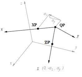
When both ZP and XP are given (no USEXP option used) the solver will compute the orientation as shown below.
The solver will compute the unit vectors doing these operations (notice vector x is redefined):

Finally, vectors x, y and z are normalized and Euler angles will be computed using the normalized unit vectors.
Case 2. ZP, XP and USEXP given
The typical example is:
MARKER/QP=1.1, 1.2, 1.3, ZP=2.1, 2.2, 2.3, XP=3.1, 3.2, 3.3, USEXP
In this case, the solver computes the orientation as shown below.
In this case the operations are (here vector z is redefined).:

Finally, unit vectors are obtained normalizing x, y and z.
Case 3. ZP given
The typical case is:
MARKER/QP=1.1, 1.2, 1.3, ZP=2.1, 2.2, 2.3
In this case, the solver will compute a point XP as shown in figure below.
The computed operations to obtain XP are:
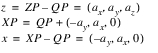
The rest of operations are the same as in Case 1.
Case 4. XP and USEXP given.
The typical case is:
MARKER/QP=1.1, 1.2, 1.3, XP=3.1, 3.2, 3.3, USEXP
In this case, the solver will compute a point ZP as shown in figure below.
The operations to compute ZP are:
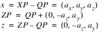
The rest of operations are the same as in Case 2.
2. Example: FE Part
The example below creates a MARKER attached to NODE_LABEL 1 of a FE_PART. The QP and REULER values define the position and orientation of the MARKER relative to the BCS of the FE_PART.
MARKER/22
, FE_PART=3
, NODE_LABEL =1
, QP = 3, 5, 6
, REULER=30D, 10D, 0
Note: | For a MARKER located exactly on a node, the QP and REULER values must be coincident with the information of the said node. |
Applications
Use markers on PARTs to:
■Designate the center of mass of a part (see the PART statement).
■Indicate the position and orientation of the coordinate system with respect to which you specify the part moment of inertia.
■Define the position and orientation of a joint or joint-primitive connection point/direction. This requires two markers, one in each part that the joint or joint primitive connects (see the JOINT and JPRIM statements).
■Denote force direction and action and reaction points. For more information, see the following statements:
■Provide coordinate system(s) other than ground coordinate system(s) for resolving the components of vector quantities such as velocities, accelerations, and forces (see the REQUEST statement).
Use floating markers on PARTs or flexible bodies to:
■Denote reaction points that can change position on a part (see the VFORCE, VTORQUE, and GFORCE statements).
Use markers on flexible bodies to:
■Define the position and orientation of a joint or joint primitive connection point/direction. This requires two markers, one in each part that the joint or joint primitive connects (see the JOINT and JPRIM statements).
■Denote force direction and action and reaction points. For more information, see the following statements:
■Provide coordinate system(s) other than ground coordinate system(s) for resolving the components of vector quantities such as velocities, accelerations, and forces (see the REQUEST statement).
Use markers on curves to:
■Define the position and orientation of a joint or joint primitive connection point/direction. This requires two markers, one in each part that the joint or joint primitive connects.
Use markers on surfaces to:
■Define the position and orientation of a joint or joint primitive connection point/direction. This requires two markers, one in each part that the joint or joint primitive connects.
See other Geometry statement available.