Flex Rim
Flex Rim Preprocess
The Flex Rim feature enables you to perform full vehicle NVH simulations in Adams Car. In current Adams version this feature is implemented for CDTire 2023.1.
The use of this feature increases validity of the Adams model to higher frequencies (300 – 400 Hz) important for NVH simulations.
This section provides a brief overview of the modeling steps in Adams environment which are specific to this modeling approach. It also describes in more detail all the preprocessing steps to get the required model files ready for building Adams model with a flexible rim.
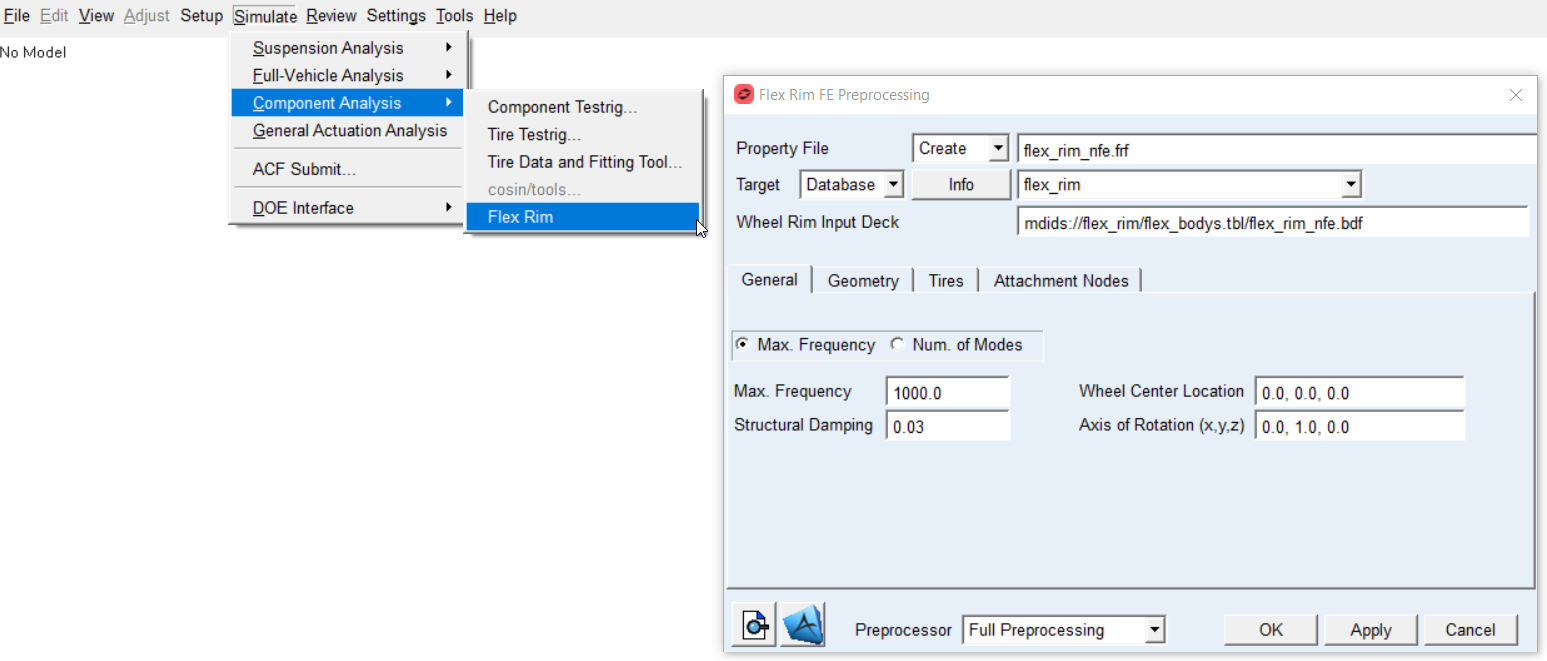
Figure 1 Access to Flex Rim FE Preprocessing
Preprocessing starts by opening Flex Rim FE Preprocessing dialog box and browsing for wheel rim input deck FE mesh (*.BDF file) prepared by user - see Figure 2.
The FE Preprocessor writes additional wheel rim bulk data files and one Nastran input deck for SOL103. The input deck references all bulk data files by INCLUDE statement and it includes all pertinent glue contact cards if defined in user wheel rim input deck BDF.
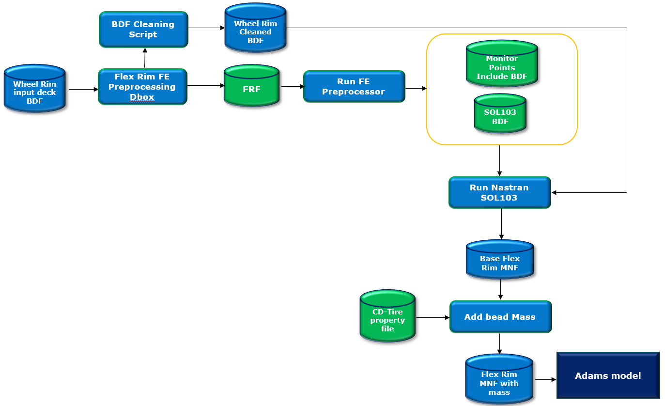
Figure 2 Data flow of Flex Rim process
After the preprocessing is complete, an MNF file will be used to create a new flexible body in Adams model.
The flexible body's local body reference frame (LBRF) corresponds to the origin of the FE structure which is transformed by FE Preprocessor to be placed in center plane of the wheel rim and the Y axis is aligned with the wheel rotational axis.
The tab options of Flex Rim FE Preprocess dialog box are following:
Main
For the options: | Do the following: |
|---|---|
Property file | The property file stores all input data entered in this dialog box, such as rim geometrical parameters, FE related parameters of a flex wheel rim (*.FRF) including file paths to tire property file and path to bulk data file. It serves as an input file to FE Preprocessor to write Nastran input deck for SOL103. In Create mode: ■Enter name of new *.FRF file In Edit mode: ■Right click to browse for existing *.FRF file ■All relevant fields in various tabs of the dialog box will be filled up by content of Flex Rim property file (.FRF) |
Target | In Database mode: ■Select destination database, the *.FRF file will be stored in flex_bodies.tbl directory. In Directory mode: ■One can use the Select icon to select destination directory for new *.FRF file. In Adams Car, there is an option menu to. |
Wheel Rim Input Deck | Browse for *.BDF file of a wheel rim FE structure. |
Preprocessor | Choose one of following options: In Create mode: ■Full Preprocessing ■Write ■FRF file only ■Mesher Only In Edit mode: ■Full Preprocessing ■Write ■FRF file only ■Mesher Only ■Nastran SOL103 only ■Add bead mass only ■Full Preprocessing: Performs all preprocessing steps mentioned below in a sequence to get all model files ready for building model with a flexible rim ■Write FRF file only: Use this option to write flex rim property file without running any preprocessing steps. ■Mesher Only: Use this option to verify that FE Mesh is valid before running SOL103 or when you need to edit Nastran input deck before Nastran job execution or in case you prefer to run Nastran job on a different computer. ■Nastran SOL103 only: Use this option after you have manually edited Nastran input deck from Mesher Only preprocessing. The SOL103 is performed by running either standalone Nastran installation if available, or the Adams embedded Nastran Solver known as ViewFlex. In case of standalone Nastran installation is used, it makes use of Nastran SMP feature with all number of processors on the compute if corresponding license is available ■Add bead mass only: Total mass of wheel rim needs to include portion of tire mass which is linked to seat for tire bead. The value of bead mass to be appended is read from CDTire property file (MASS_BEAD). A new MNF file with the bead mass is generated and the file name is stored in tire property file. |
Extended Defination:
You need to provide FE model of a wheel rim which will be processed by Flex Rim FE Preprocessor before submission of Nastran SOL103 job to get MNF file for Adams flexible body.
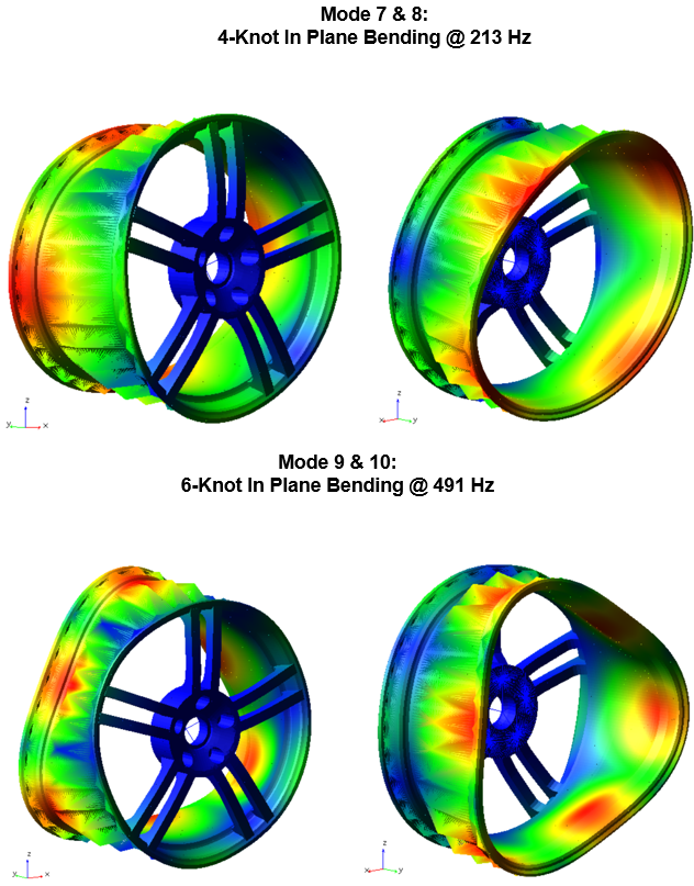
Figure 3 Example of wheel rim free-free modes
It is good practice to always verify flex body after importing to Adams. Especially check the flexible body mass and make sure that the first 6 frequencies are very close to 0.0 Hz (rigid body modes) and ensure that all these rigid body modes are disabled. In case there are 12 rigid body modes, the glue contact failed most probably due to higher distance between contact bodies than the ERROR specified in a *.bdf file. If the value of tolerance is not appropriate you can manually edit the input deck before running SOL103; search for ERROR keyword in BCONPRG Nastran card. Additionally there are some useful Nastran statements written in case control section of a *_SOL103.bdf file, which you might find helpful in troubleshooting some issues with glued contact such as plotting contact status or debugging glued contact grounding issues. Those statements are commented out but you can uncomment it before running Nastran SOL103 only preprocessor. Please read Nastran documentation to learn more about those Nastran statements.
Wheel Rim Input Deck
Flex Rim FE Preprocessor writes Nastran input deck for SOL103, which references all bulk data files by INCLUDE statement. Therefore, the wheel rim input deck provided by user must not contain executive control section, case control section and following Nastran cards and delimiters:
■CEND - delimiter at the end of executive control section
■BEGIN BULK - delimiter at the end of case control section
■EIGRL
■PARAM, AUTOMSET, YES
■PARAM, AUTOQSET, YES
■ASET / ASET1
■DTI
■ENDDATA - last entry in all the input files
Most of the non-required Nastran cards are automatically commented out right after browsing the Wheel Rim Input Deck file so you do not have to edit the file manually. The original Wheel Rim Input Deck file provided by the user is preserved with the BDF% extension. However, in case the Flex Rim FE Preprocessor or Nastran SOL103 is failing you need to check if the Wheel Rim Input Deck file is properly cleaned up.
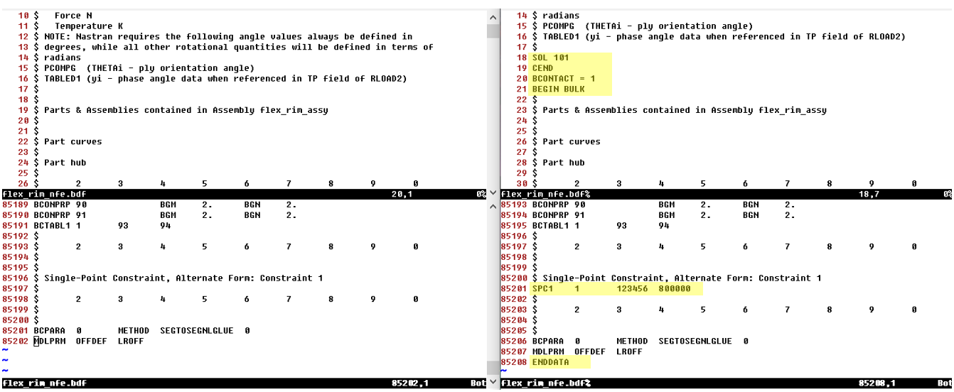
Figure 4 Original vs. cleaned up Wheel Rim Input Deck BDF file
Currently there are following prerequisites for the user FE model of the wheel rim:
■All data must be defined in following consistent set of units: MGG, N, MM, S (WTMASS = 1.0)
The Wheel Rim Input Deck file could consist of several FE meshes glued together. Flex Rim FE Preprocessor will accept those already defined - see Figure 5
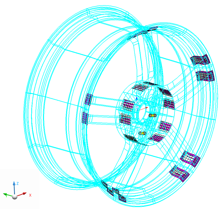
Figure 5 Contact patches of glued contact
General
The parameters of the general tab give you the possibility to control modal content of the wheel rim flexible body.
Note: | Whenever possible, you should always correlate eigen frequencies of your FE model to the modal test data. It is advised to verify flexible body before incorporating it to your Adams model, for more information read section Verifying Flexible Bodies |
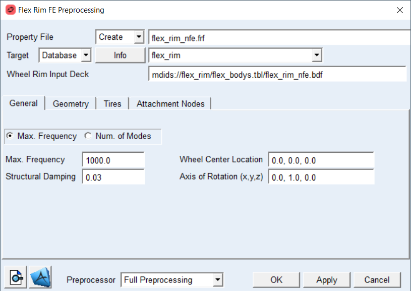
Figure 6 Flex Rim FE Preprocessing dialog box - General tab
For the options: | Do the following: |
|---|---|
If Max. Frequency radio button is selected: | |
Max. Frequency | Enter value of Max. Frequency to define cut off frequency for fixed boundary normal modes extraction during SOL103 solution process (Nastran EIGRL card). Default option: 1.0E+03 |
If Number of Modes radio button is selected: | |
Number of Modes | Enter value of Number of Modes for fixed boundary normal modes extraction during SOL103 solution process (Nastran EIGRL card). Default: 10 |
Structural Damping | Enter value of Structural Damping to define Generalizes Damping of flexible shaft. Default: 3.0E-02 |
Wheel Center Location | Enter vector in 3D to define new FE basic system. It is used by FE Preprocessor to define CORD2R card (coordinate system) so the FE structure is transformed to have the wheel rim flexible body local part reference frame located in the center of wheel rim - see Figure 7 and Figure 8 Default: 0.0, 0.0, 0.0 |
Axis of Rotation (x, y, z) | Enter vector in 3D to define axis of the wheel rim rotation in FE basic coordinate system. It is used by FE Preprocessor to define CORD2R card (coordinate system) so the FE structure is transformed to have the wheel rim flexible body rotational axis aligned with Y axis in Adams – see Figure 7 Default: 0.0, 1.0, 0.0 |
Extended definition:
Maximum Frequency: The value defines upper limit for frequency range of interest for fixed boundary normal modes extraction during SOL103 solution process. It corresponds to V2 parameter of EIGRL card – for more information read Nastran documentation.
Number of modes: Enter appropriate number of fixed boundary normal modes (also known as component dynamic modes) to define sufficiently large modal basis of your shaft / wheel body. It corresponds to ND parameter of EIGRL card – for more information read the Nastran documentation. Note that the default value of 10 will be most probably insufficient to capture real deformations of the flexible wheel rim structure.
Structural Damping: The value defines structural damping in the form of percentage of modal deformation for given mode. This damping is in contrast to modal damping proportional to deformation. The damping matrix is generated and stored in MNF file of the wheel rim assembly.
Wheel Center Location and Axis of Rotation: The wheel rim FE model gets transformed by Flex Rim Preprocessor:
■Y axis of the new FE basic system is directed along Axis of Rotation vector defined in the General tab
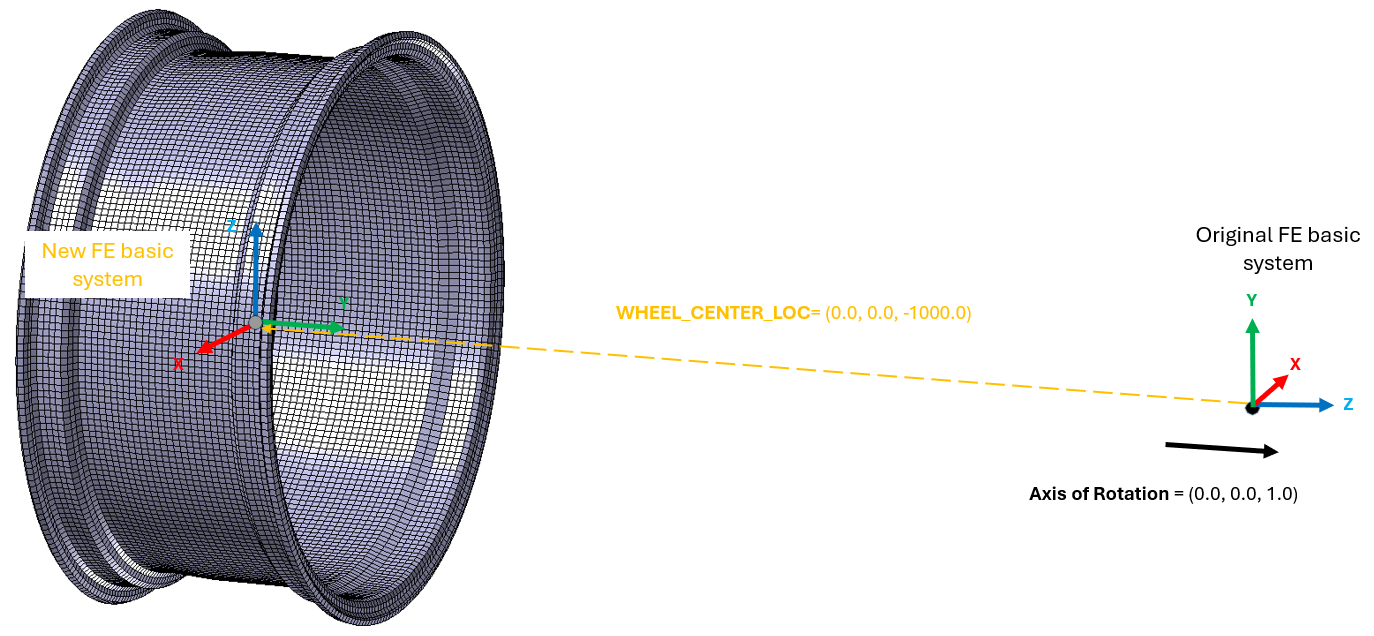
Figure 7 FE Origin and Spin Axis
Geometry
Geometrical parameters are used to automatically create monitor points over wheel rim surface.
The actual wheel rim cross-section consists of the following areas which are defined by geometrical parameters to be entered in geometry tab of the dialog box:
■Rim Horns which form the lateral seat for the tire bead (the distance between the two rims = jaw width)
■Rim Shoulders
■Well Base (Inner Base) designed as a drop rim to allow tire fitting and mostly shifted to the outside
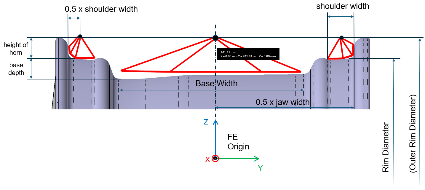
Figure 8 FE Origin geometry parameters
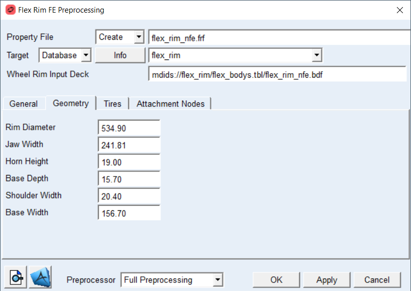
Figure 9 Flex Rim FE Preprocessing dialog box - Geometry tab
For the options: | Do the following: |
|---|---|
Rim Diameter | Enter the value of Rim Diameter |
Jaw Width | Enter the value of Jaw Width |
Horn Height | Enter the value of Horn Height |
Base Depth | Enter the value of Base Depth |
Shoulder Width | Enter the value of Shoulder Width |
Base Width | Enter the value of Base Width |
Tires
Flexible wheel rim needs to be paired with a tire to add portion of tire mass (bead mass) to flexible body. The tire property file should refer to MNF file of the flexible rim. User can preprocess more than one tire property file with single flexible wheel rim.
During the flex rim FE Preprocessing the user tire property file gets appended by MNF_RIM_FILE parameter and the original file is preserved with *.tir% backup extension. In addition, the CDTire property file needs to have one section dedicated to flex rim model, FLEXRIM_M MODEL PARAMETERS as shown on Figure 10.
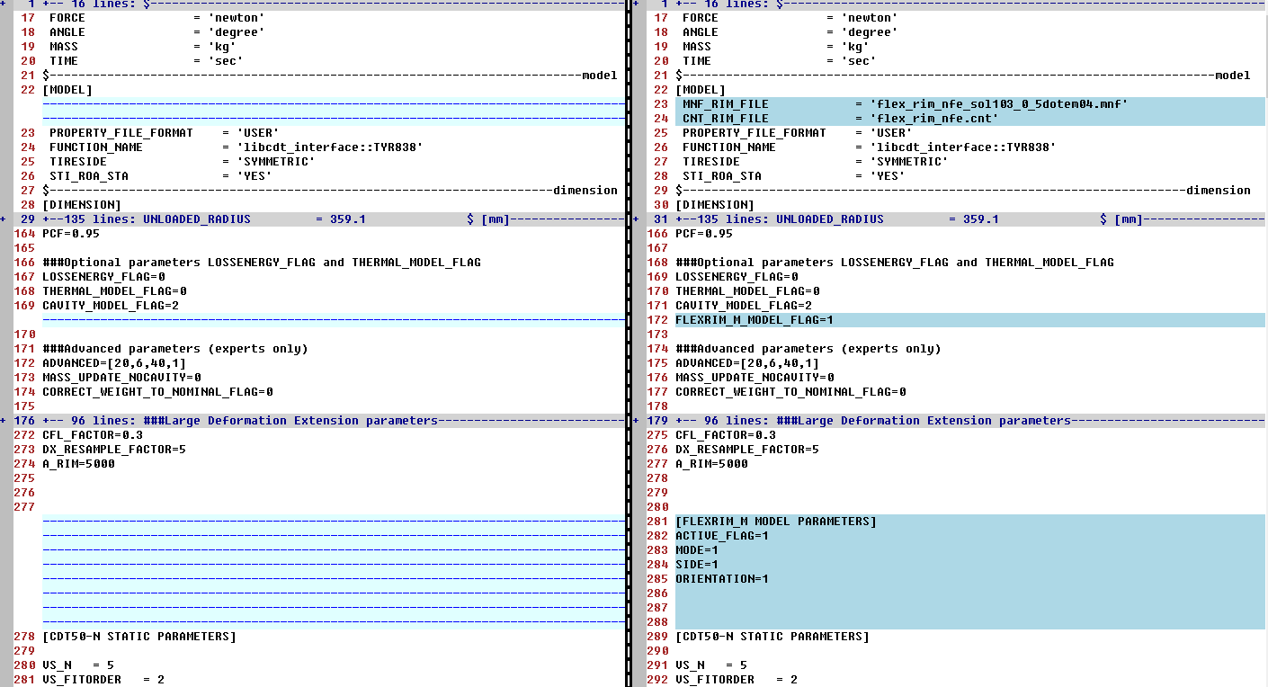
Figure 10 Tire property files
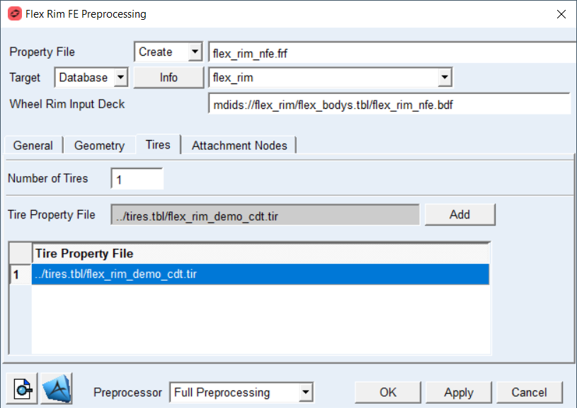
Figure 11 Flex Rim FE Preprocessing dialog box – Tires tab
For the options: | Do the following: |
|---|---|
Number of Tires | Enter the number of tires before filling up the table. Default: 1 |
Tire Property File (gray field) | This file contains all essential geometrical parameters and dimensions such as vertical stiffness, width, aspect ratio, bead mass, etc. To populate the Tire table, in gray field do a right mouse click to browse for Tire Property File (*.TIR file), then do left mouse click in a table cell and click the Add push button to fill up the cell. |
Tire Property File (cell in data table) | Fill up the column of the table by browsing in the Tire Property File field, selecting appropriate cell and the Add button. |
Attachment Nodes
To make flexible wheel rim a part of your model, Adams Car will connect it to spindle by use of fixed joint.
To capture the effects of attachments on the flexible body the modal basis also needs to include so called constraint modes (boundary DOF). This is achieved by usage of RBE2 and RBE3 elements and promoting its reference node to be so called attachment or interface node by ASET1 Nastran card. You also need to define attachment degrees of freedom in Nastran SOL103 analysis set which are defined in the new FE basic system, where X-axis and Z-axis are normal to the wheel rim axis of rotation and Y-axis coincides with rotational axis – see Figure 7.
The table in Attachment Nodes tab is automatically populated by all reference grids of RBE2, RBE3 and ASET cards found in the Wheel Rim Input Deck you provided however it could be expanded and edited appropriately.
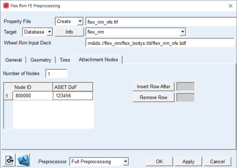
Figure 12 Flex Rim FE Preprocessing dialog box –Attachment Nodes tab
For the options: | Do the following: |
|---|---|
Number of Nodes | Enter the number of required attachment nodes. This field is auto populated by the content of the Wheel Rim Input Deck you provided however it could be edited appropriately. Default is 1 |
Node ID | Enter the Node ID of the flexible wheel rim attachments – see Figure 13. This column of the table is auto populated by the content of the Wheel Rim Input Deck you provided however it could be edited appropriately. |
ASET DoF | Define degrees of freedom (DOF) per attachment node to be used in the modal analysis which refer to the new FE basic system – see Figure 7. 1 = X-axis translation 2 = Y-axis translation 3 = Z-axis translation 4 = X-axis rotation 5 = Y-axis rotation 6 = Z-axis rotation For example, if you want to apply fixed joint to attachment node enter 123456. To apply spherical joint enter 123. Default is 123456 Note: Make sure you hit the enter key after you define the value in table. Otherwise your value will not be applied. |
Insert Row After | In case the value of Number of Nodes is small, one can increase the number. Enter the number of the row after which you want the new row to be added into the table, the value of Number of Nodes field will be updated automatically. Afterwards, enter the required Node ID value in the newly created cell and also enter the value of DoF. |
Remove Row | In case that the value of Number of Nodes is large, you can decrease the number. Enter the number of the row which you want to remove from the table, the value of Number of Nodes field will be updated automatically. |
 | The button displays the content of the *.FRF property file. |
 | The button allows you to browse for Nastran bulk data file and opens the FE model in MSC Apex. |
Extended definition:
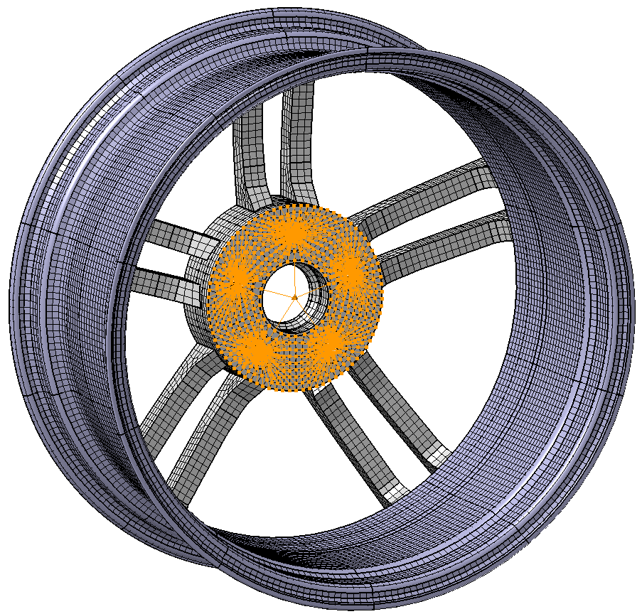
Figure 13 Hub mounting face - attachment RBEs
Number of Nodes: Before executing Nastran SOL103 you need to define attachment nodes of the flex rim body to spindle part (also known as interface node) which will be written in the MNF file and will be used to connect the flexible body to other parts and elements of your Adams model. Typically, there is one attachment node per flexible wheel rim to connect to, however the table is populated by all nodes found in BDF file which are defined as reference node of RBE2 and RBE3 elements. User need to remove those from table which are not applicable.
Node ID: Enter the node ID of flexible wheel rim attachment. This node should belong either to RBE2 or RBE3 element.
ASET DoF: Enter the degree of freedom (DoF) per attachment node of your wheel rim FE model. When you build a flexible body into an Adams model, you interface with the body using a variety of attachments, either joints or forces. In Adams Flex, you can model the variable boundary conditions at attachment points, which are nodes that have been idealized for attachment, by preserving all six Cartesian degrees of freedom (DoFs) of those points as you export the flexible body from your finite element analysis (FEA) program. An attachment point is equivalent to a superelement exterior grid point. Each attachment point normally contributes six modal DOF. Corresponding to each attachment point DOF is one constraint mode, which is a static mode shape due to a unit displacement of that DOF while holding all other DOFs of all attachment points fixed. A large number of attachment points can result in unwieldy data files and can significantly impact CPU time, if the associated modes are enabled during an Adams dynamic simulation. It is advised to limit the number of constraint modes by prescribing adequate DoFs per attachment node. For instance, if you intend to model spherical joint, it is enough to preserve translational DoF for the ASET (123). However, the ASET for attachment of flexible wheel rim should always preserve all DoFs (123456).