Using Pacejka '89 Handling Force Model
Learn about the Pacejka '89 handling force model:
Coordinate System and Units in Pacejka '89
The equations for the force and moment calculation in the Pacejka ‘89 tire model follow the SAE coordinate system, the units follow the conventions as specified in the Table ‘Conventions for Naming Variables’ below. Note that the ‘Magic Formula’ parameters in the tire property file will also follow these conventions. However, the results from Adams Solver as presented in the Adams Postprocessor can adhere a different coordinate system or use different units. This depends on the type of requests that are being used, see the Adams Tire request definitions in section Outputting Results.
Note: | The section [UNITS] in the tire property file does not apply to the Magic Formula coefficients. |
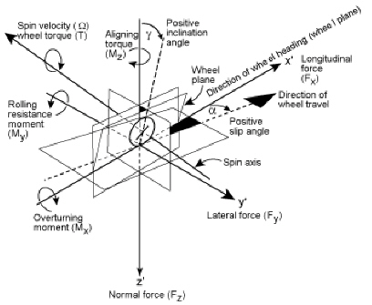
Figure 1 SAE Tire Coordinate System
Conventions for Naming Variables
Variable name and abbreviation: | Description: | |
|---|---|---|
Normal load | Fz (kN) | Positive when the tire is penetrating the road.* |
Lateral force | Fy (N) | Positive in a right turn. Negative in a left turn. |
Longitudinal force | Fx (N) | Positive during traction. Negative during braking. |
Self-aligning torque | Mz (Nm) | Positive in a left turn. Negative in a right turn. |
Inclination angle |  (degree) (degree) | Positive when the top of the tire tilts to the right (when viewing the tire from the rear).* |
Sideslip angle |  (degree) (degree) | Positive in a right turn.* |
Longitudinal slip |  (%) (%) | Negative in braking (-100%: wheel lock). Positive in traction. |
* Opposite convention to standard SAE coordinate system shown in SAE Tire Coordinate System. | ||
Force and Moment Formulation for Pacejka '89
Longitudinal Force for Pacejka '89
C - Shape Factor
C=B0
D - Peak Factor
D=(B1*FZ2+B2*FZ)
BCD
BCD=(B3*FZ2+B4*FZ)*EXP(-B5*FZ)
B - Stiffness Factor
B=BCD/(C*D)
Horizontal Shift
Sh=B9*FZ+B10
Vertical Shift
Sv=0.0
Composite
X1=(κ+Sh)
E Curvature Factor
E=(B6*FZ2+B7*FZ+B8)
FX Equation
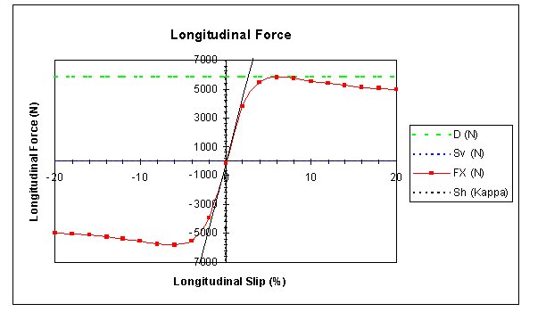
FX=(D*SIN(C*ATAN(B*X1-E*(B*X1-ATAN(B*X1)))))+Sv
Longitudinal Force
Parameters: | Description: |
|---|---|
B0 | Shape factor |
B1, B2 | Peak factor |
B3, B4, B5 | BCD calculation |
B6, B7, B8 | Curvature factor |
B9, B10 | Horizontal shift |
Example Longitudinal Force Plot for Pacejka ’89
Lateral Force for Pacejka '89
C - Shape Factor
C=A0
D - Peak Factor
D=(A1*FZ2+A2*FZ)
BCD
BCD=A3*SIN(ATAN(FZ/A4)*2.0)*(1.0-A5*ABS(γ))
B - Stiffness Factor
B=BCD/(C*D)
Horizontal Shift
Sh=A9*FZ+A10+A8*γ
Vertical Shift
Sv=A11*FZ*γ+A12*FZ+A13
Composite
X1=(α+Sh)
E - Curvature Factor
E=(A6*FZ+A7)
FY Equation
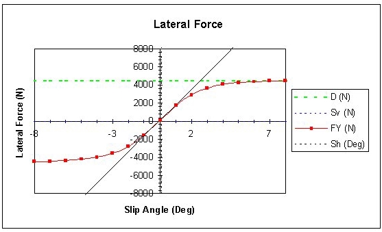
FY=(D*SIN(C*ATAN(B*X1-E*(B*X1-ATAN(B*X1)))))+Sv
Parameters for Lateral Force
Parameters: | Description: |
|---|---|
A0 | Shape factor |
A1, A2 | Peak factor |
A3, A4, A5 | BCD calculation |
A6, A7 | Curvature factor |
A8, A9, A10 | Horizontal shift |
A11, A12, A13 | Vertical shift |
Example Lateral Force Plot for Pacejka ’89
Self-Aligning Torque
C - Shape Factor
C=C0
D - Peak Factor
D=(C1*FZ2+C2*FZ)
BCD
BCD=(C3*FZ2+C4*FZ)*(1-C6*ABS(γ))*EXP(-C5*FZ)
B - Stiffness Factor
B=BCD/(C*D)
Horizontal Shift
Sh=C11*γ+C12*FZ+C13
Vertical Shift
Sv= (C14*FZ2+C15*FZ)*γ+C16*FZ+C17
Composite
X1=(α+Sh)
E - Curvature Factor
E=(C7*FZ2+C8*FZ+C9)*(1.0-C10*ABS(γ))
MZ Equation
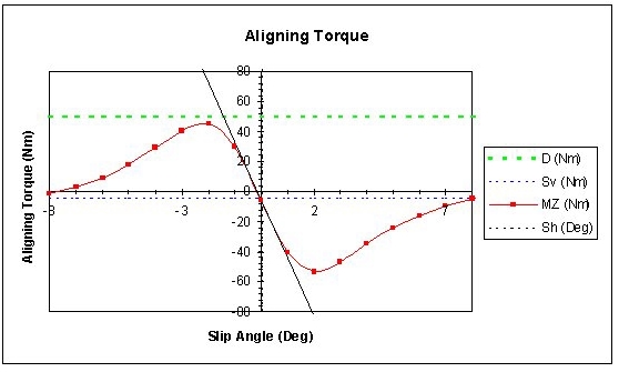
MZ=(D*SIN(C*ATAN(B*X1-E*(B*X1-ATAN(B*X1)))))+Sv
Parameters for Self-Aligning Torque
Parameters: | Description: |
|---|---|
C0 | Shape factor |
C1, C2 | Peak factor |
C3, C4, C5, C6 | BCD calculation |
C7, C8, C9, C10 | Curvature factor |
C11, C12, C13 | Horizontal shift |
C14, C15, C16, C17 | Vertical shift |
Example Self-Aligning Torque Plot for Pacejka ’89
Overturning Moment
The lateral stiffness is used to calculate an approximate lateral deflection of the contact patch when there is a lateral force present:
deflection = Fy / lateral_stiffness
This deflection, in turn, is used to calculate an overturning moment due to the vertical force:
Mx (overturning moment) = -Fz * deflection
And an incremental aligning torque due to longtiudinal force (Fx)
Mz = Mz,Magic Formula + Fx * deflection
Here Mz,Magic Formula is the magic formula for aligning torque and Fx * deflection is the contribution due to the longitudinal force.
Rolling Resistance
The rolling resistance moment My is opposite to the wheel angular velocity. The magnitude is given by:
My = Fz * Lrad * rolling_resistance
Where Fz equals the vertical force and Lrad is the tyre loaded radius. The rolling resistance coefficient can be entered in the tire property file:
[PARAMETER]
ROLLING_RESISTANCE = 0.01
A value of 0.01 introduces a rolling resistance force that is 1% of the vertical load.
Smoothing
When you indicate smoothing by setting the value of use mode in the tire property file, Adams Tire smooths initial transients in the tire force over the first 0.1 seconds of simulation. The longitudinal force, lateral force, and aligning torque are multiplied by a cubic step function of time. (See STEP in the Adams Solver online help.)
Longitudinal Force
FLon = S*FLon
Lateral Force
FLat = S*FLat
Overturning Moment
Mx = S*Mx
Rolling resistance moment
My = S*My
Aligning Torque
Mz = S*Mz
The USE_MODE parameter in the tire property file allows you to switch smoothing on or off:
■USE_MODE = 1 or 2, smoothing is off
■USE_MODE = 3 or 4, smoothing is on
Example of Pacejka '89 Property File
$---------------------------------------------------------MDI_HEADER
[MDI_HEADER]
FILE_TYPE = 'tir'
FILE_VERSION = 2.0
FILE_FORMAT = 'ASCII'
(COMMENTS)
{comment_string}
'Tire - XXXXXX'
'Pressure - XXXXXX'
'Test Date - XXXXXX'
'Test tire'
$-------------------------------------------------------------UNITS
[UNITS]
LENGTH = 'mm'
FORCE = 'newton'
ANGLE = 'radian'
MASS = 'kg'
TIME = 'sec'
$-------------------------------------------------------------MODEL
[MODEL]
! use mode 1 2 3 4 11 12 13 14
! ---------------------------------------------------------------
! smoothing X X X X
! combined X X X X
! transient X X X X
!
PROPERTY_FILE_FORMAT = 'PAC89'
USE_MODE = 12.0
TYRESIDE = 'LEFT'
$----------------------------------------------------------DIMENSION
[DIMENSION]
UNLOADED_RADIUS = 326.0
WIDTH = 245.0
ASPECT_RATIO = 0.35
$----------------------------------------------------------PARAMETER
[PARAMETER]
VERTICAL_STIFFNESS = 310.0
VERTICAL_DAMPING = 3.1
LATERAL_STIFFNESS = 190.0
ROLLING_RESISTANCE = 0.0
$---------------------------------------------------------LOAD_CURVE
$ For a non-linear tire vertical stiffness (optional)
$ Maximum of 100 points
[DEFLECTION_LOAD_CURVE]
{pen fz}
0 0.0
1 212.0
2 428.0
3 648.0
5 1100.0
10 2300.0
20 5000.0
30 8100.0
$-----------------------------------------------LATERAL_COEFFICIENTS
[LATERAL_COEFFICIENTS]
a0 = 1.65000
a1 = -34.0
a2 = 1250.00
a3 = 3036.00
a4 = 12.80
a5 = 0.00501
a6 = -0.02103
a7 = 0.77394
a8 = 0.0022890
a9 = 0.013442
a10 = 0.003709
a11 = 19.1656
a12 = 1.21356
a13 = 6.26206
$--------------------------------------------------------longitudinal
[LONGITUDINAL_COEFFICIENTS]
b0 = 1.67272
b1 = -9.46000
b2 = 1490.00
b3 = 30.000
b4 = 176.000
b5 = 0.08860
b6 = 0.00402
b7 = -0.06150
b8 = 0.20000
b9 = 0.02990
b10 = -0.17600
$----------------------------------------------------------aligning
[ALIGNING_COEFFICIENTS]
c0 = 2.34000
c1 = 1.4950
c2 = 6.416654
c3 = -3.57403
c4 = -0.087737
c5 = 0.098410
c6 = 0.0027699
c7 = -0.0001151
c8 = 0.1000
c9 = -1.33329
c10 = 0.025501
c11 = -0.02357
c12 = 0.03027
c13 = -0.0647
c14 = 0.0211329
c15 = 0.89469
c16 = -0.099443
c17 = -3.336941
$--------------------------------------------------------------shape
[SHAPE]
{radial width}
1.0 0.0
1.0 0.2
1.0 0.4
1.0 0.5
1.0 0.6
1.0 0.7
1.0 0.8
1.0 0.85
1.0 0.9
0.9 1.0