Simulations and Results
Performing Simulations
Once you have incorporated the required statements for modeling a tire into your dataset, you can submit the dataset for simulation. Both the standard Adams Solver and the Adams Car solver can be used.
To submit your dataset to the Adams Solver, do the following:
In a command window, submit your dataset for simulation using the following commands:
■For Linux and Linux platforms, enter:
adams2024_1 -c ru-standard
■For Windows platforms, enter:
adams2024_1 ru-standard
To submit your dataset to the Adams Car solver, do the following:
In a command window, submit your dataset for simulation using the following commands:
■For Linux and Linux platforms, enter:
adams2024_1 -c acar ru-standard
■For Windows platforms, enter:
adams2024_1 acar ru-standard
Note: | If your Adams Dataset uses a 3D Spline Road .xml file, the Adams Car solver should be used. |
Outputting Results
The user request REQ902 can output predefined tire results into the request (.req) and results (.res) files. The form of the request statement is:
REQUEST/id
, FUNCTION = USER(902, REQTYP, TIR_ID)/
, ROUTINE = abgTire::req902
where
■902 - Branch flag for tire request subroutine.
■REQTYP - Integer code fixing the information output to the request file. The output for each value of REQTYP is described in the table.
■TIR_ID - Tire GFORCE statement ID.
For information on the axis systems and sign conventions for these outputs, see About Axis Systems and Sign Conventions.
Table 1 Tire Outputs
Output: | REQTYP Request: | Component definitions: | Adams Car Tire Request Activity Name |
|---|---|---|---|
Tire rolling states | 23 | x = tire deflection y = loaded rolling radius (= unloaded radius - tire deflection) z = effective rolling radius1 r1 = actual angular velocity (=  ) of the wheel (rad/sec or degree/sec) ) of the wheel (rad/sec or degree/sec) | radius_request |
Tire kinematic properties in TYDEX-W axis (ISO) system. | 2 | x = longitudinal slip (%) y = lateral slip angle (degree or radian) z = inclination angle (degree or radian) (below 1 m/s the slip is scaled down) | kinematics_request_ISO |
Exact Tire kinematic properties in ISO axis system | 25 | x = longitudinal slip (%) y = lateral slip angle (degree or radian) (no down scaling applied) | kinematics_exact_request_ISO |
Tire kinematic properties in SAE axis system | 5 | x = longitudinal slip (%) y = lateral slip angle (degree or radian) z = inclination angle (degree or radian) (below 1 m/s the slip is scaled down) | kinematics_request_SAE |
Tire contact patch forces in TYDEX-W axis (ISO) system | 3 | x = longitudinal force (model units) y = lateral force (model units) z = vertical force (model units) r1 = residual overturning moment (model units) r2 = rolling resistance moment (model units) r3 = aligning moment (model units) | forces_request_ISO |
Tire contact patch forces in SAE axis system | 4 | x = longitudinal force (model units) y = lateral force (model units) z = vertical force (model units) r1 = residual overturning moment (model units) r2 = rolling resistance moment (model units) r3 = aligning moment (model units) | forces_request_SAE |
Forces at hub, in global axis system specified by the road reference marker | 6 | x = longitudinal force (model units) y = lateral force (model units) z = vertical force (model units) r1 = overturning moment (model units) r2 = rolling resistance moment (model units) r3 = aligning moment (model units) | hub_forces_request |
Contact patch locations (the contact patch location along the plane of the tire in the GFORCE reference marker’s coordinate system.) | 10 (refer the notes below) | x = road contact point X location y = road contact point Y location z = road contact point Z location r1 = tire radial penetration into the road surface r2 = tire radial penetration velocity into the road surface | n/a |
Hub and wheel velocities | 11 | x = longitudinal hub velocity in wheel carrier (TYDEX-C) axis system  y = longitudinal slip velocity at the contact patch in the contact patch axis system  z = lateral slip velocity at the contact patch in the contact patch axis system  | velocity_request |
Friction coefficients | 12 | x = longitudinal friction coefficient y = lateral friction coefficient z = road friction as defined in the road property file | friction_request |
Road normal components in global axis system specified by the road reference marker | 13 | x = x component of the road normal y = y component of the road normal z = z component of the road normal | road_normal_request |
Tire sinkage and soil deformation (Soft Soil tire model) | 15 | x = plastic sinkage (in case of the plastic-elastic model, h-he) y = elastic sinkage (he) z = viscous sinkage (in case of the visco-elastic model, h-he) r1 = stored plastic deformation of the soil from a previous tire (multipass) r2 = stored elastic deformation of the soil from a previous tire (multipass) r3 = stored viscous deformation of the soil from a previous tire (multipass) | n/a |
Tire soil contact stress info (Soft Soil tire model) | 16 | x = contact entry angle (  ) )y = contact exit angle (  ) )z = angle with max normal stress (  ) )r1 = max normal stress (  ) )r2 = max shear stress in longitudinal direction (  ) )r3 = max shear stress in lateral direction (  ) ) | n/a |
Tire deflection and radii (Soft Soil tire model) | 17 | x = tire deflection (f0) y = tire loaded rolling radius (Rl) z = tire effective rolling radius (Re) r1 = actual angular velocity (=  ) of the wheel (rad/sec or degree/sec) ) of the wheel (rad/sec or degree/sec)r2 = substitution radius (R*) r3 = total sinkage (plastic + elastic + visco) | soft_soil_request |
Effective inputs of 3D Enveloping Contact | 18 | x = effective road height y = effective road slope z = effective road inclinations r1 = effective road curvature r2 = contact patch length r3 = contact patch width | enveloping_contact_request |
Contact patch location and orientation in global axis system specified by the road reference marker | 19 (refer the notes below) | x = road contact patch X location y = road contact patch Y location z = road contact patch Z location r1 = psi euler angle contact patch r2 = theta euler angle contact patch r3 = phi euler angle contact patch | contact_patch_request |
Forces at the hub, in Tydex C-axis system according to ISO | 26 | x = longitudinal force (model units) y = lateral force (model units) z = vertical force (model units) r1 = overturning moment (model units) r2 = rolling resistance moment (model units) r3 = aligning moment (model units) | hubc_forces_request_ISO |
Forces at the hub, in Tydex C-axis system according to SAE | 27 | x = longitudinal force (model units) y = lateral force (model units) z = vertical force (model units) r1 = overturning moment (model units) r2 = rolling resistance moment (model units) r3 = aligning moment (model units) | hubc_forces_request_SAE |
Forces at the hub, in Tydex H-axis system according to ISO | 28 | x = longitudinal force (model units) y = lateral force (model units) z = vertical force (model units) r1 = overturning moment (model units) r2 = rolling resistance moment (model units) r3 = aligning moment (model units) | hubh_forces_request_ISO |
Forces at the hub, in Tydex H-axis system according to SAE | 29 | x = longitudinal force (model units) y = lateral force (model units) z = vertical force (model units) r1 = overturning moment (model units) r2 = rolling resistance moment (model units) r3 = aligning moment (model units) | hubh_forces_request_SAE |
1The definition of the effective rolling radius is different for each tire model, see the specific tire model documentation. If nothing is mentioned about the effective tire rolling radius, the loaded radius is taken.
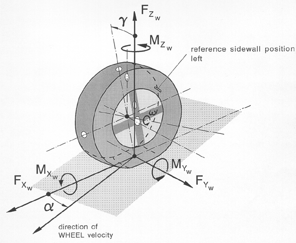
Figure 1 TYDEX W-axis system in ISO orientation
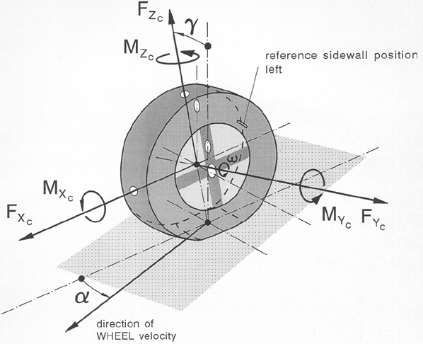
Figure 2 TYDEX C-axis system in ISO orientation
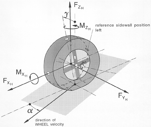
Figure 3 TYDEX H-axis system in ISO orientation
Notes: | The ID =10 and ID = 19 requests supply the same contact patch location information, but in a different coordinate system. Request ID = 19 is also used for the tire force visualization as available in Adams Car. Therefore request ID = 19 also contains the orientation of the contact 'patch'. All Adams Tire models have one point of contact in which the tire forces are applied, though the method for calculating the contact point is different. Adams Tire supports four contact methods, see also 'Contact Methods'. Depending on the contact method the location of the contact point can be different: ■One Point contact: Result of the intersection of the wheel plane with the tangent road plane below the wheel center. ■Equivalent Volume contact: The 3D Shell Road utilizes a three-dimensional tire-to-road contact model that computes the volume of intersection between the road and the tire. From the intersection volume the method computes an equivalent plane's effective road normal, penetration, tire to road contact point, and effective road friction. ■Cross Section contact (used by PAC-MC only): Due to the cross section shape of the tire, the contact point will be shifted in lateral direction depending on the inclination angle of the wheel with the road. ■3D Enveloping contact: The enveloping contact will result in a different contact point position. With the position of the 'tandem cams' on the road surface an effective height, slope and road inclination will be calculated. FTire: Since FTire models a complete contact patch, the single contact point coordinates returned via req902 (id=10 and 19) are an approximation to be consistent with the simpler 'handling' type of tire models that actually use a single point contact algorithm. The contact point is computed below the wheel center looking along an approximated road normal. This road normal is constructed using a plane through the wheel center, a point before the wheel center and a point to the left of the wheel center. |
Special requests are available for the Soft Soil tire model, see Specific requests for the Soft-Soil Tire Model and for the 3D Enveloping Contact, see Specific requests for the 3D Enveloping Contact.
Differences in between tire contact (patch) forces and hub forces
The tire contact (patch) forces (request types 3 and 4) have a different location and orientation than the hub forces (request types 6, 26, 27, 28, 29).
The tire contact forces are located at the contact point in between the tire and the road. This contact point is calculated as the intersection in between the wheel plane and the road plane (tangent road plane).
The tire contact forces are oriented in a local coordinate system (W-axis) and 'move' with the tire. The longitudinal force is along the intersection line of the wheel plane and the road tangent plane. The lateral force is perpendicular to this intersection line in the road tangent plane. The vertical axis is along the normal on the road tangent plane.
The hub force requests have different coordinate systems: request type 6 is a global coordinate system, request type 26, 27, 28 and 29 in a local system (C or H axis) moving with the wheel.
The hub force request (26-28) in a local system are usually close to the tire contact forces, but sign and size may differ due to the orientation and camber effects, see the definition of C-axis, H-axis, ISO and SAE systems. One more difference may occur in case of a tire model with belt dynamics: The weight of the belt will be included in the tire contact forces but not in the hub forces. So in a steady state situation the difference in vertical contact and hub force is the weight of the tire belt.