Curves
Learn more:
About Curve Data Elements
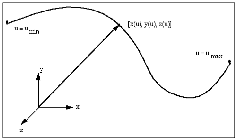
The x, y, and z coordinates of a point on a parametric curve are functions of an independent parameter, alpha. As alpha varies from its minimum value to its maximum value, the functions x(alpha), y(alpha), and z(alpha) sweep out points on the curve. A simple example of a parametric curve is the helix defined by the following equations:
x = cos(alpha)
y = sin(alpha)
z = alpha
Ways to Use Curve Data Elements
A curve data element defines a three-dimensional parametric curve that you can reference when:
■Creating a higher-pair constraint - When you create or modify a Point-Curve Constraints or 2D Curve-Curve Constraints, you can pick the geometric curves that you've created from the curve element or you can modify the point- or curve-curve constraint to use a different curve.
■Creating a part - You can use the curve that you create in the definition of a part. For example, when you create a construction geometry spline using the geometric modeling tools as explained in Creating Splines, Adams View automatically creates a curve element defining the spline. You could replace the default curve element with a curve element that you create. You could also create an empty part using the Table Editor, and modify it to contain a curve element.
■Writing function expressions - You can use the curve element as the input to a function, such as CURVE(B-Spline fitting method). For more information on using curves in a function expression, see Spline Functions in Adams View Function Builder online help.
Defining Data Element Curves
You can define a data element curve using:
■Subroutine - To use a different type of curve or to model an analytically defined curve, such as a helix, you can write a CURSUB User-written subroutine to compute the curve coordinates and derivatives. See the Subroutines section of the Adams Solver online help. You can also specify an alternative library and name for the user subroutine. Learn about specifying your own routine with ROUTINE Argument.
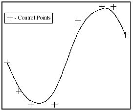
Adams View defines a b-spline using control points that form a polygon in space and a knot vector. It computes the control points internally from the curve points. Adams View uses a non-uniform knot vector with quadruple multiplicity at both ends. The curve starts at the first control point and ends at the last. In between, it is attracted to, but does not necessarily hit, the intermediate control points. Adams View parameterizes a b-Spline starting at -1 and ending at +1. The figure below shows a set of control points and the b-spline curve it defines.
Control Points and the Resulting B-Spline
Steps in Defining a Curve
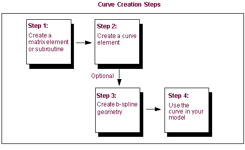
To create a curve using curve or data points that are defined in a matrix element or using a User-written subroutine, you perform the steps listed in the figure below.
About Specifying Open or Closed Curves
A data element curve can be open or closed. A closed curve meets at the ends, connecting the curve at minimum and maximum parameter values. An open curve does not meet at the ends.
If you create an open curve, Adams View does not allow a point-curve (see Point-Curve Constraints) or 2D curve-curve (see Curve-Curve Constraints) contact point to move beyond the end of the curve. Adams View, however, automatically moves a point-curve or curve-curve constraint contact point across the closure of a closed curve, if needed. For example, you can model a cam profile as a closed curve, and Adams View allows the follower to move across the closure as the cam rotates.
Adams View stops the simulation if a point-curve or curve-curve constraint contact point is prescribed to move off the end of the curve. You should ensure that the curve defined includes the expected range of contact.
Using Curve Elements in Your Model
Once you've created a curve element, you can use it to define a higher-pair constraint, as geometry of a part, or in a function expression.
■Higher-Pair Constraint - When you create or modify either Point-Curve Constraints or Curve-Curve Constraints, you can pick the geometric curves that you've created from the curve element or you can modify the point- or curve-curve constraint to use a different curve.
■Geometry of a part - You can use the curve that you create in the definition of a part. For example, when you create a Construction geometry spline using the geometric modeling tools as explained in Creating Splines, Adams View automatically creates a curve element defining the spline. You could replace the default curve element with a curve element that you create. You could also create an empty part using the Table Editor, and modify it to contain a curve element.
■Function expression - You can use the curve element as the input to a function, such as CURVE (B-Spline fitting method). See Spline Functions in Adams View Function Builder online help.
Creating and Modifying Curve Data Elements
To create or modify a curve data element:
1. Click the Elements tab. From the Data Elements container, click the Curve tool .
.
. or
(Classic interface) From the Build menu, point to Data Elements, point to Curve, and then select either New or Modify.
2. If you selected:
■Modify, the Database Navigator appears. Select a data element curve to modify. The Data Element Modify Curve dialog box appears. It contains the same options as the Data Element Create Curve dialog box.
3. If creating the curve, accept the default name or assign a new name.
4. Assign a unique ID number to the curve element, if desired.
5. Add or change any comments about the curve element to help you manage and identify it.
6. Set Closed to no to create an open curve or yes to create a closed curve.
7. Set the pull-down menu in the middle of the dialog box for how you want to define the curve (either from a matrix or a User-written subroutine). The dialog box changes depending on the selection you made. Learn more about Defining Data Element Curves.
8. If you are entering values using a matrix, enter values in the dialog box as explained in the table below, and then select OK.
To set: | Do the following: |
|---|---|
Matrix to be used | In the Matrix Name text box, enter the matrix name. Tips on Entering Object Names in Text Boxes. |
Interpolation order | Specify the order of the b-spline interpolating the curve. The order is 1 plus the degree of the functions used to define the spline. The order also affects the number of points used to determine each spline segment. For example, splines of order 2 are basically polylines, while the segments used to create an spline of order 4 are of the 3rd order. 4 is the default order of splines, which is a cubic b-spline. Note: B-splines of order K will have K - 2 continious derivatives. The discontinuities appear where the polynomial segments join together. Increasing the order of the b-spline arbitrarily may introduce unwanted oscillation into the curve. |
9. If you are entering values using a subroutine, enter values in the dialog box as explained in the table below, and then select OK.
To set: | Do the following: |
|---|---|
User-written subroutine to be used | In the User Function text box, enter the subroutine name. You can also specify an alternative library and name for the subroutine in the Routine text box. Learn about specifying your own routine with ROUTINE Argument. Tips on Entering Object Names in Text Boxes. |
Minimum and maximum curve parameters | Enter the following: Minimum Parameter - Enter the minimum value of the curve parameter for a user-written curve. Maximum Parameter - Enter the maximum value of the curve parameter for a user-written curve. |