UDE Definition Creation
Creating a UDE Definition is a complex task. One must carefully consider how the objects within it can interact with the rest of the model and how they will be able to be relocated throughout the model as instances as well as what parameterization of those objects should be exposed when creating instances. This section describes these considerations along with the steps of creating a UDE Definition.
Recommended Preparation for Creating UDE Definition
Overall you want the set of objects representing your UDE definition to be a well parameterized movable portion of your model able to stand alone. To those ends, strongly consider the following recommendations:
■Parameterize for Instance Properties: What is it you want consumers of the UDE definition to be able to change about it when creating instances? Anything that falls into that category should be specified via design variables up front before you create the UDE definition. The design variables you assign to object properties in your model will be identified as candidates for required entries on instance creation dialogs.
■Parameterize to Move: In most cases, UDE’s are intended to be spread throughout space in a model. So, objects you select should be parameterized in such way as to have their location and orientation determined by something(s) outside the UDE, typically one or more markers. That way when creating an instance one or more markers can be specified and all the objects will fall into the correct place.
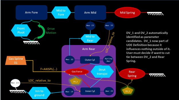
■Avoid Design Variables with Influence beyond the UDE: Design variables that influence objects inside your intended definition and outside of it should be avoided. Upon creating a UDE definition any such design variables will need to be reconciled as either influencing the UDE or the rest of the model, but not both.
Choosing Topological Objects
The first step in creating a UDE definition is choosing what you want to compose it. Adams View uses the term topological objects for this starting point because the objects selected need not include supporting items like design variables and force graphics. The Adams View UDE definition creation dialog will automatically account for such items.
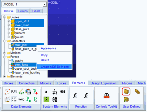
You can specify the topological object set in one of two ways. One way is through the model browser where you multi-select the objects then right-click and choose Create UDE Definition. The other way is through the ribbon where you navigate to Elements – User Defined and click the Create UDE Definition icon.
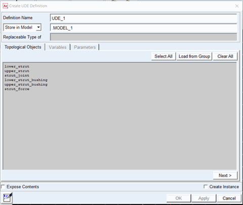
Both these actions launch the Create UDE Definition dialog. The topological objects tab will be populated with those items chosen from the model browser, or empty if you came to the dialog via the ribbon icon.
You can edit the topological object list a number of ways from this dialog:
■Select All: selects all objects currently in the model
■Load from Group: selects all objects within an Adams View group
■Clear All: removes all objects from the Topological Objects field
■Right-Click Menu: right-clicking within the Topological Objects field enables one to pick or browse for objects
Again, because these are topological objects you need not include supporting items. The following items will be automatically detected and included in the UDE definition:
■Force graphic objects corresponding to any force objects in the topological object set
■Design variables which influence objects in the topological object set
■In general, if a child object is selected then its parent will automatically get selected. For example, geometry will auto-select parent part.
■Non modeling items are automatically filtered out. For example, gravity, analysis_scripts and so on.
■No UDE instance is selectable except certain allowed UDE instances listed next: spring, torsion_spring, general_motion, vpg_road, vpg_tire, controls_plant, controls_gain, controls_input, controls_integrator, controls_lead_lag, controls_low_pass, controls_pid, controls_second_order, controls_sum, controls_switch, controls_transfer_function
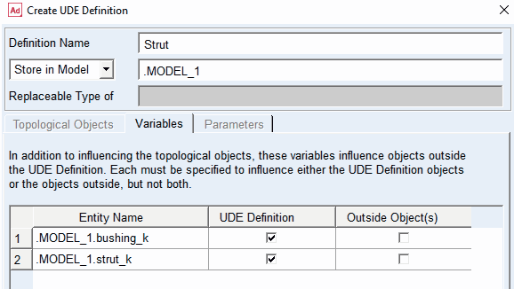
Design Variables with Influence beyond the UDE
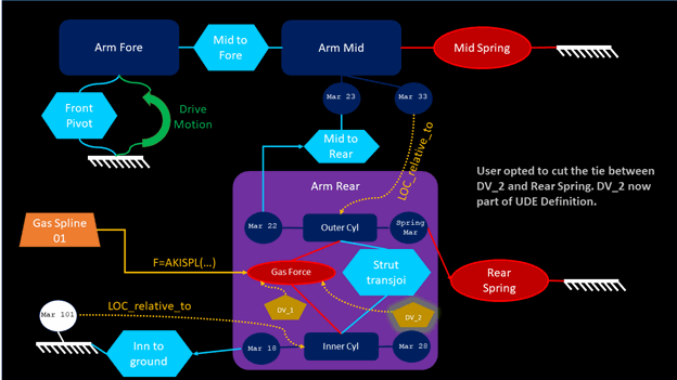
As stated in the previous section, the UDE definition creation dialog will identify design variables that influence the topological object set. If any of those design variables also currently influence objects in the model that are outside of the topological object set, then upon clicking Next from the “Topological Objects” tab you are directed to the “Variables” tab. In this tab, for each of the design variables in question, you must choose between the UDE definition and the rest of the model. That is, these design variables will not be allowed to continue to influence objects in both the UDE and the model. So, you must choose. For the objects not chosen, their values will be changed to the current value of the design variable that formerly parameterized them.
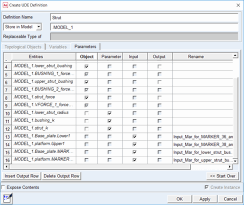
Objects vs. Parameters
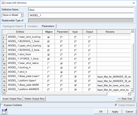
Upon clicking Next from the “Topological Objects” tab (or the “Variables” tab) you are taken to the “Parameters” tab. This is where all entities in the model identified as part of the UDE Definition are sorted by type: Object, Parameter, Input and Output.
This section describes sorting objects and parameters.
The “Parameters” tab will list all the topological objects specified on the “Topological Objects” tab and any design variables in the model which influence them. The topological objects are categorized as type “Object” and there is no ability to change this. The design variables are by default categorized as type “Parameter.” This means they will appear as fields on the creation dialog for UDE instances of this definition so that users can specify their value when creating instances (they become the “general_parameter” object type under a “ude_definitition” in the Adams View database). If you do not want to expose a given design variable in this manner, then you must toggle to the category selection from “Parameter” to “Object.” Then, the design variable value cannot be set during instance creation and its current value will be applied when creating any instances.
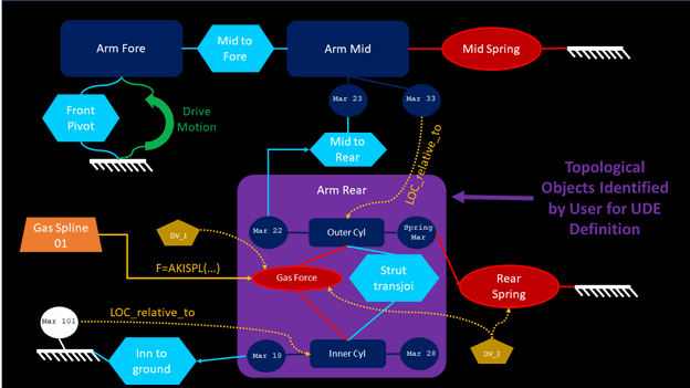
The diagrams below are a schematic of a model and illustrate an example of the design variables that would be identified based on a UDE definition’s topological objects’ relationship to the rest of the model:
Inputs
Upon clicking Next from the “Topological Objects” tab (or the “Variables” tab) you are taken to the “Parameters” tab. This is where all entities in the model identified as part of the UDE Definition are sorted by type: Object, Parameter, Input and Output.
Managing Inputs
Inputs are any entities outside the UDE definition’s topological object set referenced by the UDE definition. They become an “input_parameter” object under a “ude_definitition” in the Adams View database. Typical examples are markers that are used to locate objects in the definition (for example, via a parametric expression) or markers that complete an object in the UDE definition’s topological object set (for example, the J marker of a joint or force whose I marker is on a part within the definition).
The topological objects in the UDE definition cannot exist in a model without these inputs being specified a value. Therefore, there is no ability to toggle these inputs to another category in the table. During instance creation these inputs must be assigned a value; so, a field will be present for each of them on the instance creation dialog. You can use the “Rename” column in the table to edit the default name to something more meaningful to users creating instances.
Note: | In this release, you cannot rename inputs or outputs after this point (that is, when modifying the UDE definition later) |
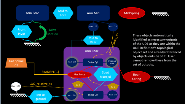
The diagram below is a schematic of a model and illustrates an example of the inputs that would be identified based on a UDE definition’s topological objects’ relationship to the rest of the model:

Outputs
Upon clicking Next from the “Topological Objects” tab (or the “Variables” tab) you are taken to the “Parameters” tab. This is where all entities in the model identified as part of the UDE Definition are sorted by type: Object, Parameter, Input and Output.
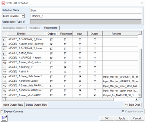
Managing Outputs
Outputs are any entities inside the UDE definition’s topological object set that should be accessible outside the UDE. They become an “output_parameter” object under a “ude_definitition” in the Adams View database. Typical examples are markers on parts within your UDE definition used by joints or forces outside the UDE definition. Such items cannot have their type toggled from output to something else in this tab. But, you can add outputs to your UDE definition. A typical example is a marker that you want exposed for use as an input to a different UDE. You need not declare markers that you might want to hook up to normal (that is, non-UDE-resident) objects in your model. Such markers are always available to you through either the model browser or the command navigator.
During instance creation outputs must be assigned a value; so, a field will be present for each of them on the instance creation dialog. You can use the “Rename” column in the table to edit the default name to something more meaningful to users creating instances.
Note: | In this release, you cannot rename inputs or outputs after this point (that is, when modifying the UDE definition later). |
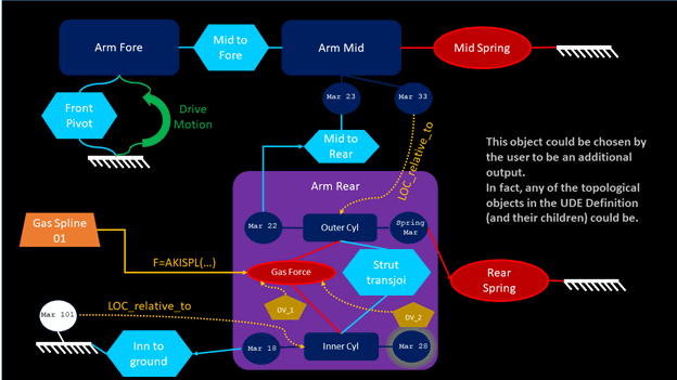
The diagram below is a schematic of a model and illustrates an example of the outputs that would be identified based on a UDE definition’s topological objects’ relationship to the rest of the model and one that could be added by the user:
Storing a UDE Definition
UDE definitions can be stored either in a library or in a model.
Storing in a Library
If stored in a library the UDE definition will not be included when exporting an Adams View command file of a model (even if that model contains instances based on the UDE definition). Typically library storage of UDE definitions is done by organizations that have groups of Adams experts responsible for developing and sharing modeling methodology. Then, other colleagues using Adams have a procedure to access the expert library and update their Adams sessions with it (typically via an Adams View command file, like the aview.cmd, that automatically loads the library into a session).
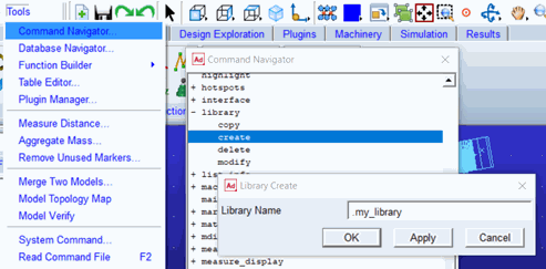
It is recommended that you create your own libraries in which to store your own UDE definitions, as opposed to storing them in MSC-shipped libraries that come with Adams View. To create a library go to Tools – Command Navigator – library – create and specify a name at the top level of the database like shown below:
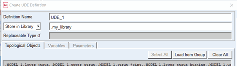
You can then choose this library in the UDE Definition Create dialog when specifying where you want to store your UDE definition:
Note that libraries (including any UDE definitions in them) can be shared via so-called “partial binary” files. These can be exported from an Adams View session from the command navigator: Tools – Command Navigator – file – binary – write. In the ensuing dialog specify “File Name” and in the “Entity Name” field browse for the library/libraries you want to include and click OK.
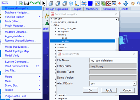
The .bin file will be written to the current working directory and can be shared with others who consume it via File – Open Database like any other .bin files.
Storing in a Model
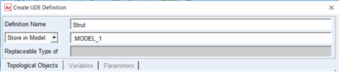
To store your UDE definition in a model, no up-front preparation is necessary. Simply specify the model name in the UDE Definition Create dialog. If stored in a model the UDE definition is included when exporting an Adams View command file of a model by way of a second .cmd file specifically for the definition which is referenced by the model’s .cmd file. See Files Associated with UDE’s for more information.
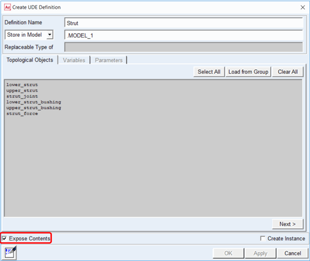
Exposing Contents of a UDE Definition
The contents of UDE definitions stored in a model are exposed under it in the model browser. The contents of UDE instances are exposed within the model browser only if the “Expose Contents” checkbox is selected when creating the UDE definition.